Loading ...
Loading ...
Loading ...
2.7.7 MOTOR
1. Remove the cabinet. (Refer to section 2.5.2)
2. Remove the air guide. (Refer to section 2.6.1)
3. Remove the blower, (Refer to section 2.6.2)
4. Remove the fan. (Refer to section 2.6.3)
5, Remove the shroud. (Refer to section 2.6.3)
6, Remove the control box. (Refer to section 2.5.3)
7, Remove the 2 screws which fasten the motor.
8. Remove the motor.
9. Re-install the components by referring to the
above removal procedure,
2.8 REFRIGERATION CYCLE
2.8.1 CONDENSER
1. Remove the cabinet. (Refer to section 2.5.2)
2. Discharge the refrigerant system using a Freon_
Recovery System.
If there is no valve to attach the recovery system,
install one (such as a WATCO A-l) before venting
the FreonTM. Leave the valve in place after servic-
ing the system.
3. Remove the 4 screws which fasten the condenser.
4. After discharging the refrigerant completely,
detach the interconnecting tube at the condenser
connections.
5. Remove the condenser.
6. Re-install the component by referring to notes.
2.8.2 EVAPORATOR
1. Remove the cabinet. (Refer to section 2.5.2)
2. Discharge the refrigerant system using a FreonTM
Recovery System.
If there is no valve to attach the recovery system,
install one (such as a WATCO A-l) before venting
the FreonTM. Leave the valve in place after servic-
ing the system.
3. Remove the cover E,P.S and the upper air guide
(Refer to section 2.6.1)
4. After discharging the refrigerant completely,
detach the interconnectingtube at the evaporator
connections.
5. Remove the evaporator.
6. Re-install the component by referring to notes.
2.8.3 CAPILLARY TUBE
1. Remove the cabinet. (Refer to section 2.5.2)
2. Remove the upper air guide. (Refer to section
2.6.1)
3. Discharge the refrigerant system using a Freon_
Recovery System.
Ifthere is no valve to attach the recovery system,
install one (such as a WATCO A-l) before venting
the FreonTM. Leave the valve in place after servic-
ingthe system.
4. After discharging the refrigerant completely,
detach the interconnecting tube at the CAPIL-
LARY TUBE.
5. Remove the CAPILLARY TUBE.
6. Re-install the component by referring to notes.
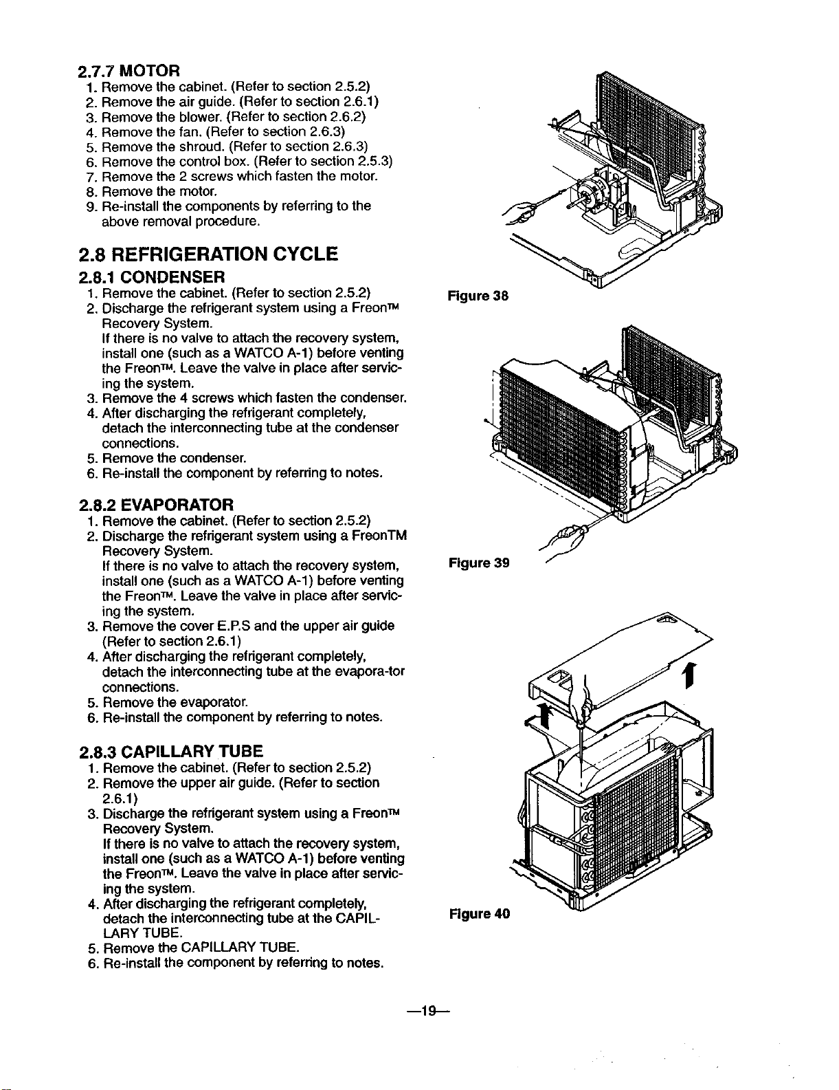
Figure 38
Figure 39
Figure 40
m19--
Loading ...
Loading ...
Loading ...