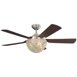
Owner's Guide Ceiling Fans
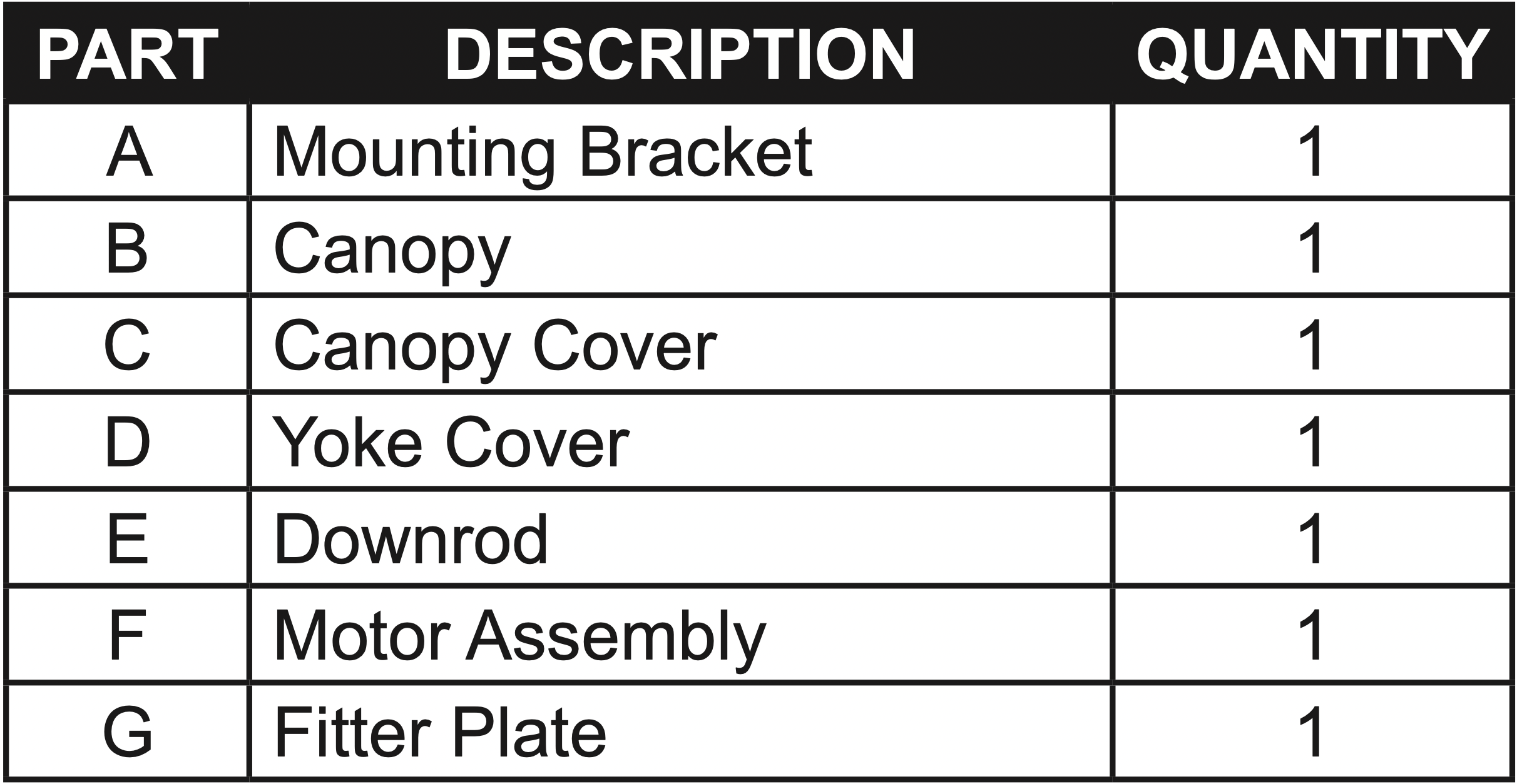
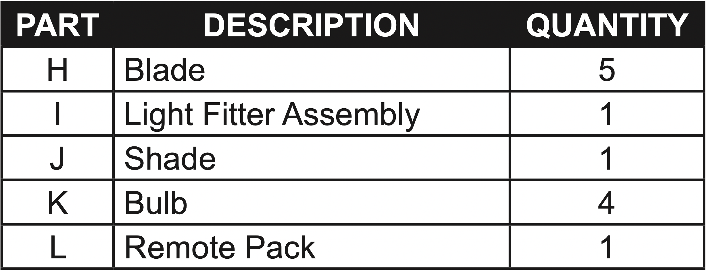
PACKAGE CONTENTS
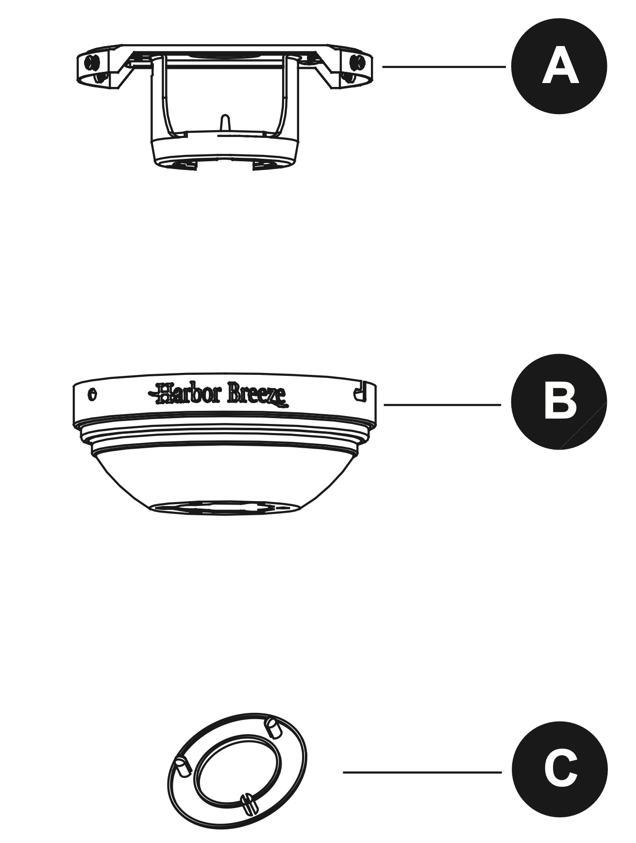
HARDWARE CONTENTS (shown actual size)
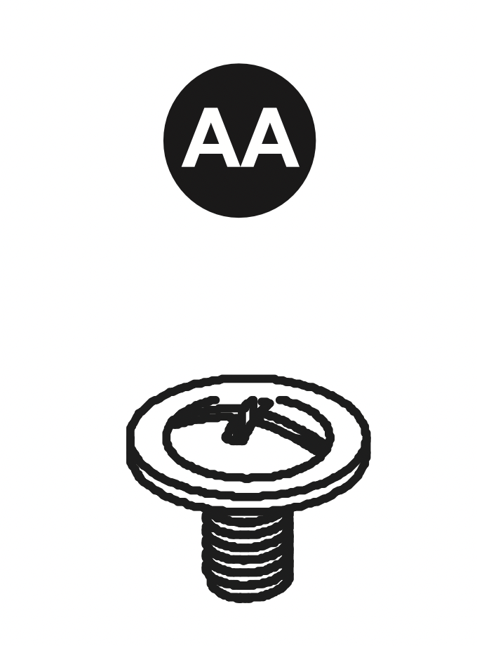
Blade Screw Qty. 16
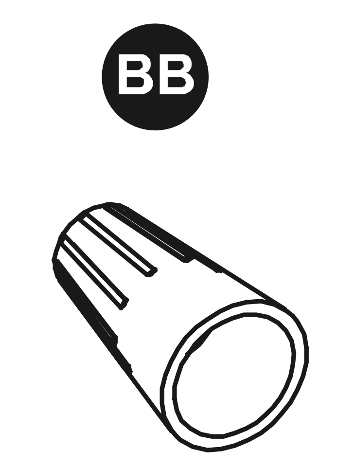
Wire Connector Qty. 9
ASSEMBLY INSTRUCTIONS
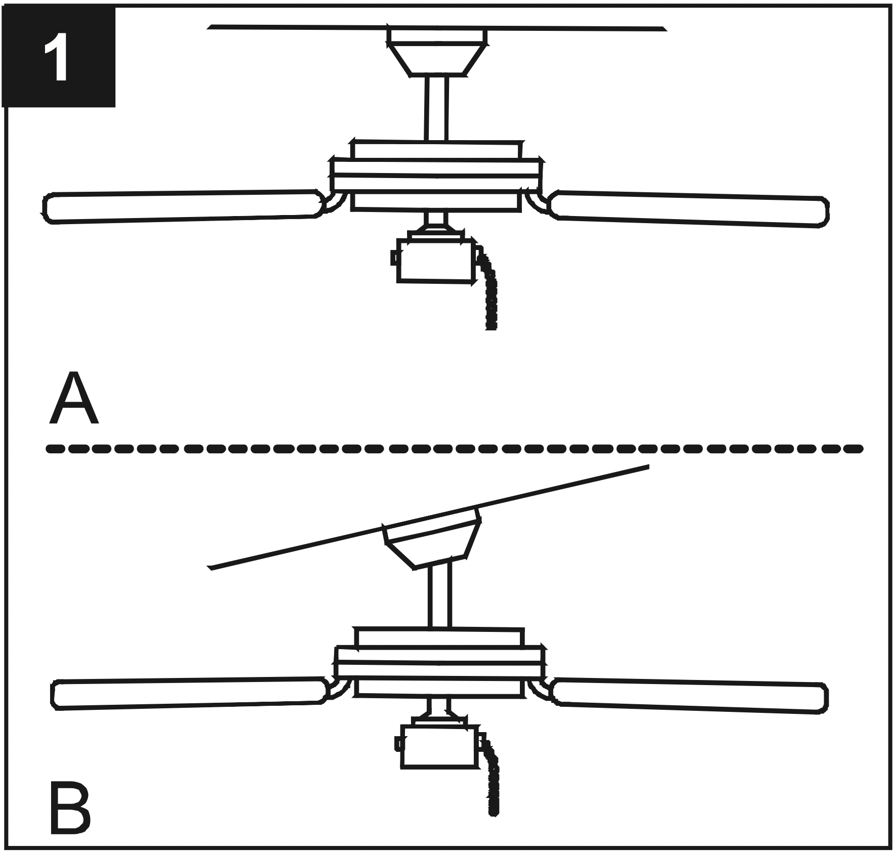
1. Determine mounting method to use.
A - Downrod Mount
B - Angle Mount
Important: If using the angle mount, check to make sure the ceiling angle is not steeper than 20˚
2. Remove the mounting bracket (A) from the canopy (B) by loosening the four screws on the top of the canopy (B). Remove the two non-slotted screws and save.
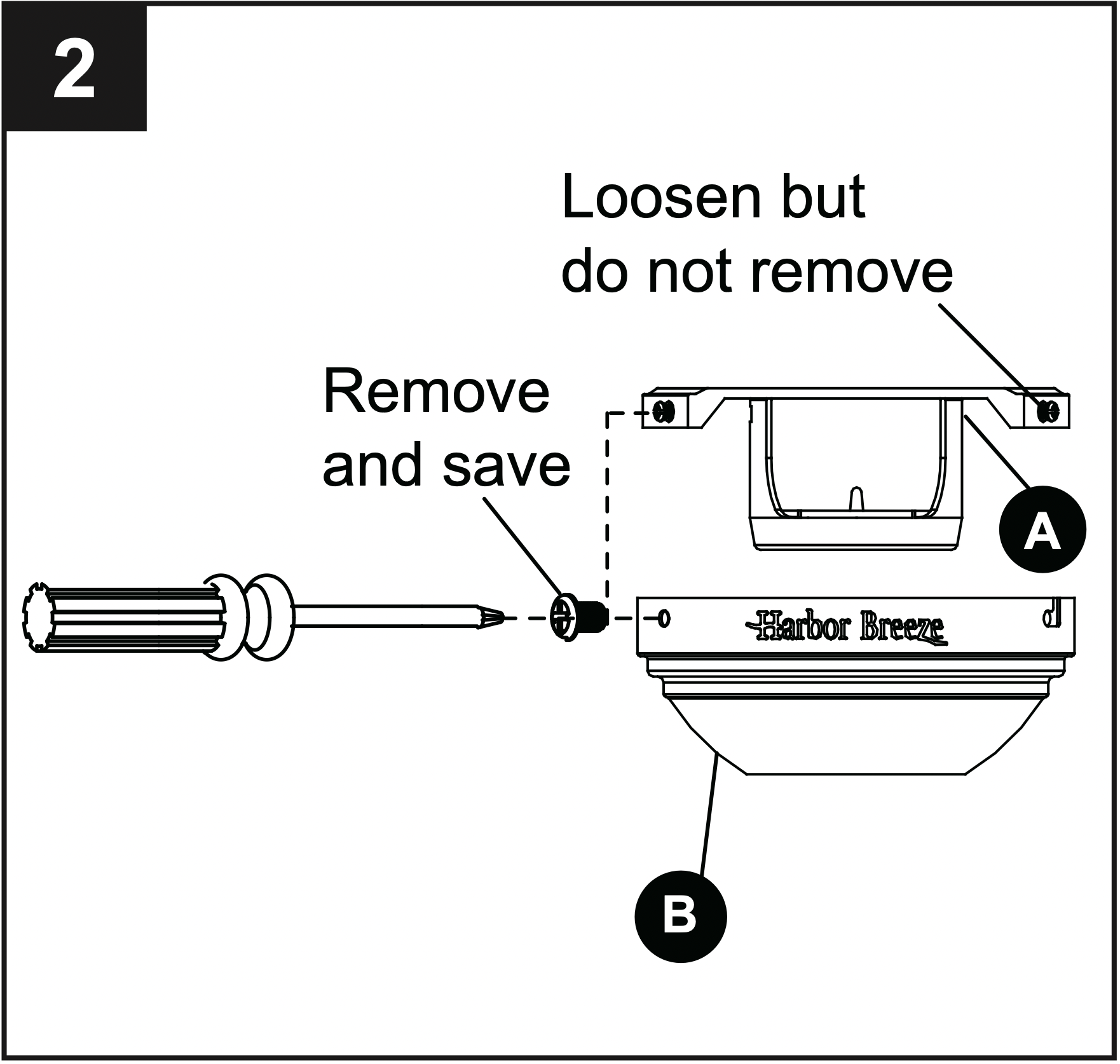
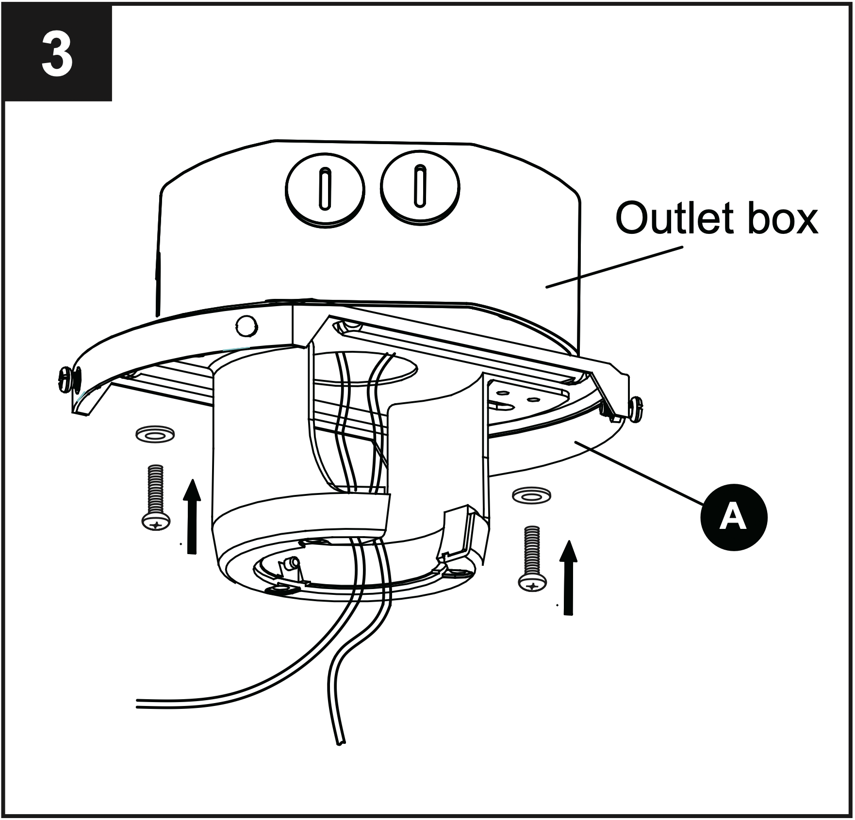
3. Install mounting bracket (A) to outlet box (not included) by sliding mounting bracket (A) over the two outlet box screws (not included). Securely tighten two outlet box screws.
IMPORTANT: If angle mounting, make sure open end of mounting bracket (A) is installed facing the ceiling.
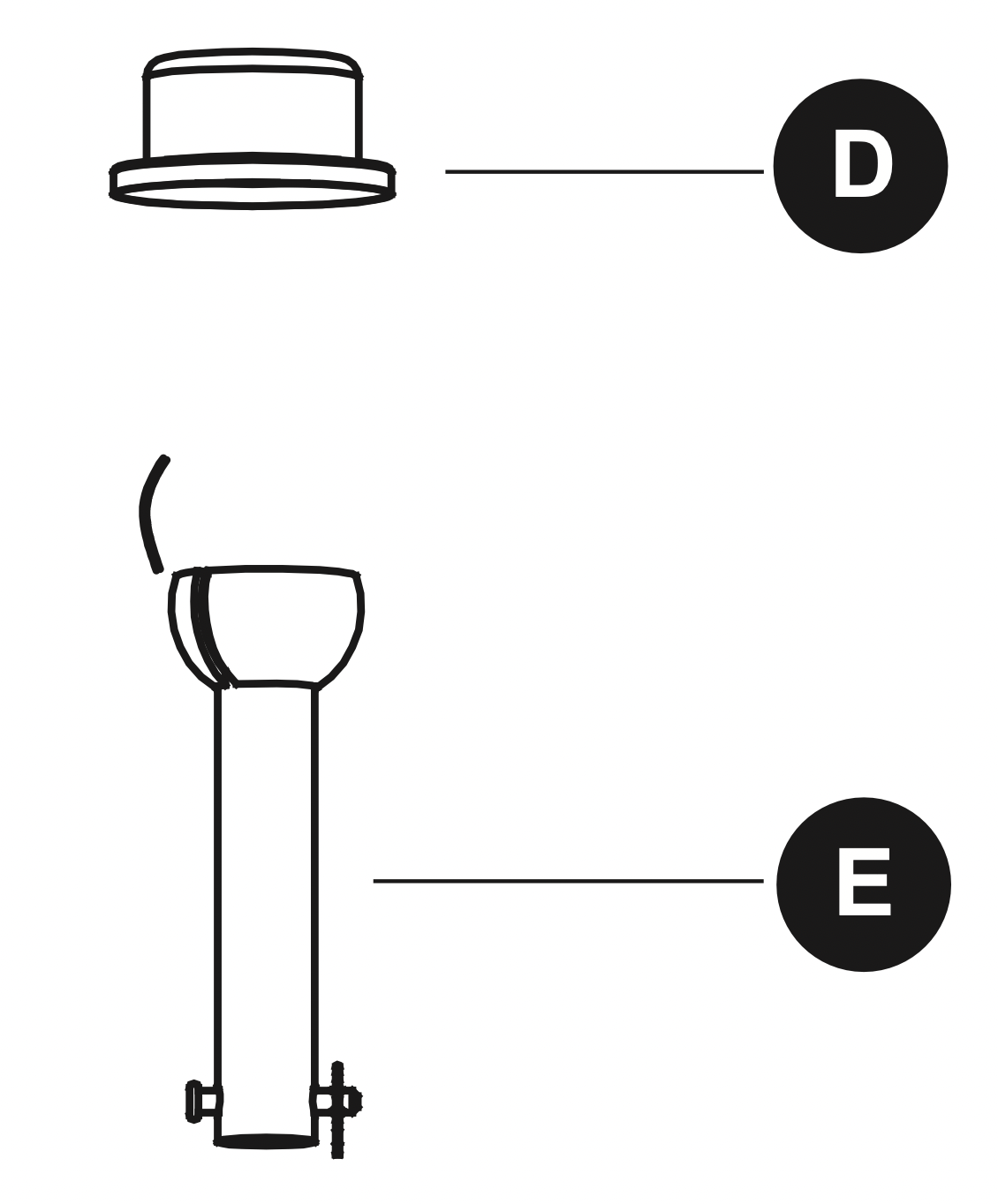
4. Remove the preassembled pin and clip from downrod (E). Insert downrod (E) through canopy (B) and yoke cover (D). Thread wires from fan motor assembly (F) through downrod (E).
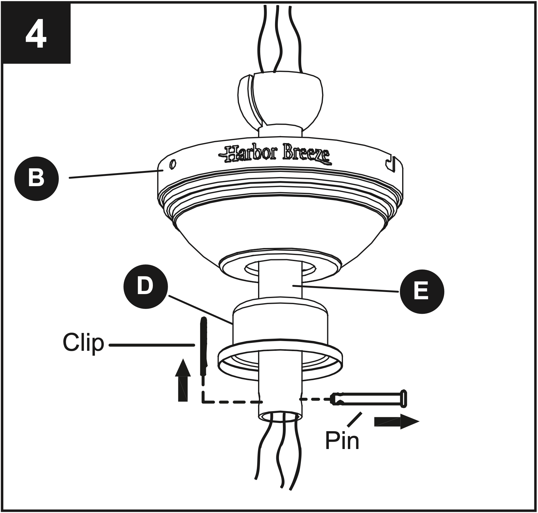
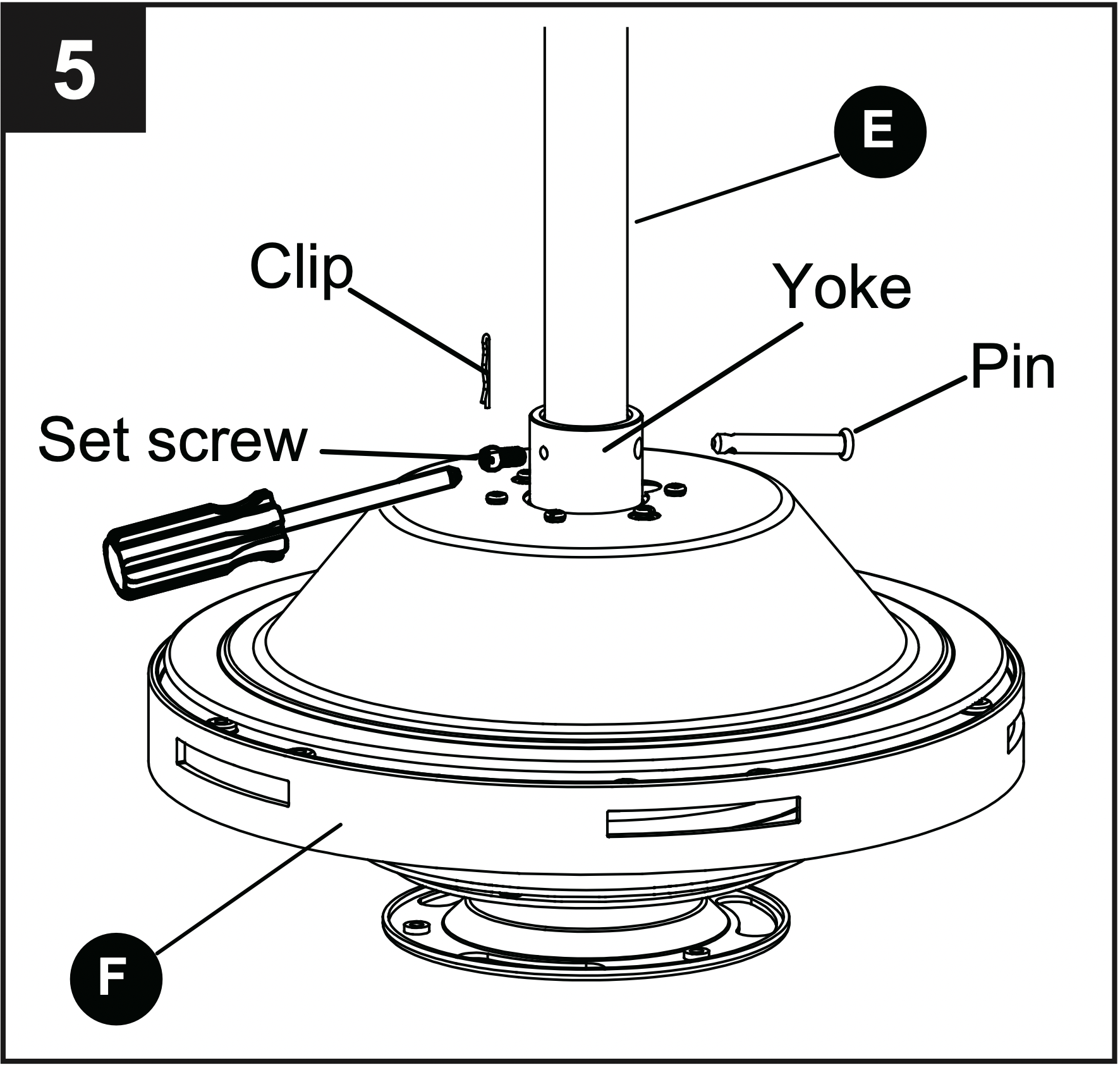
5. Loosen the two set screws from the yoke. Slip downrod (E) into the yoke, then re-insert pin and clip. Tighten set screws to secure.
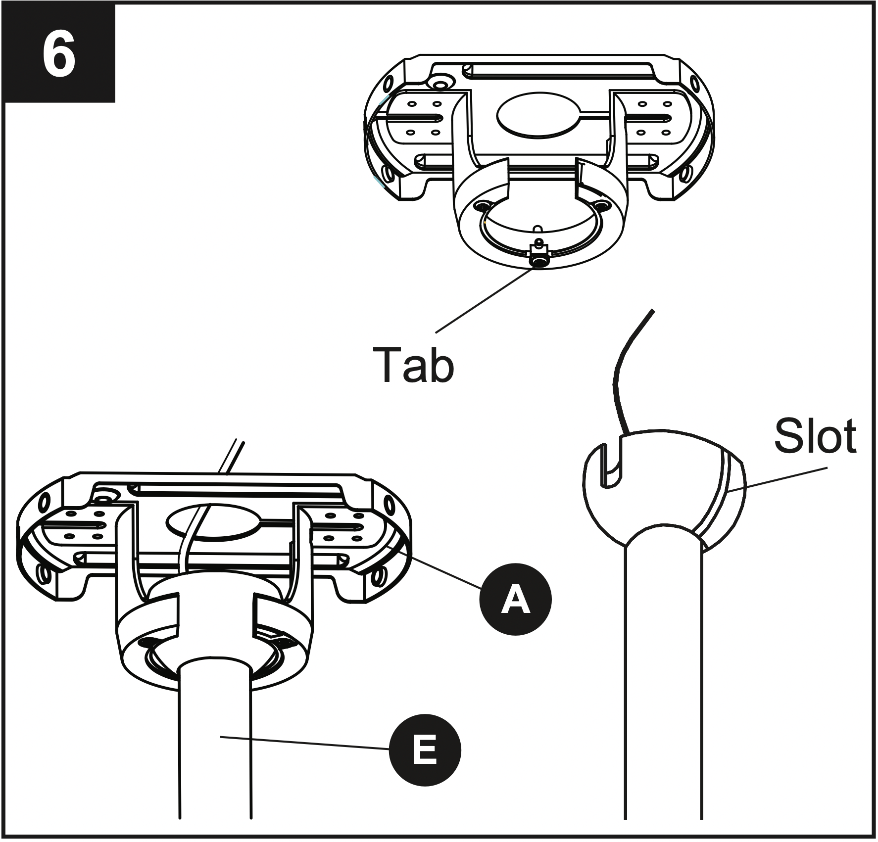
6. Carefully lift the motor assembly (F) up to the mounting bracket (A). Install hanger ball on the top of downrod (E) into opening of mounting bracket (A). Rotate fan until slot on hanger ball engages the tab on the mounting bracket (A).
DANGER: Be careful when aligning the tab to the slot! If not fully engaged, there is a possibility of fan falling, which may result in serious injury or death.
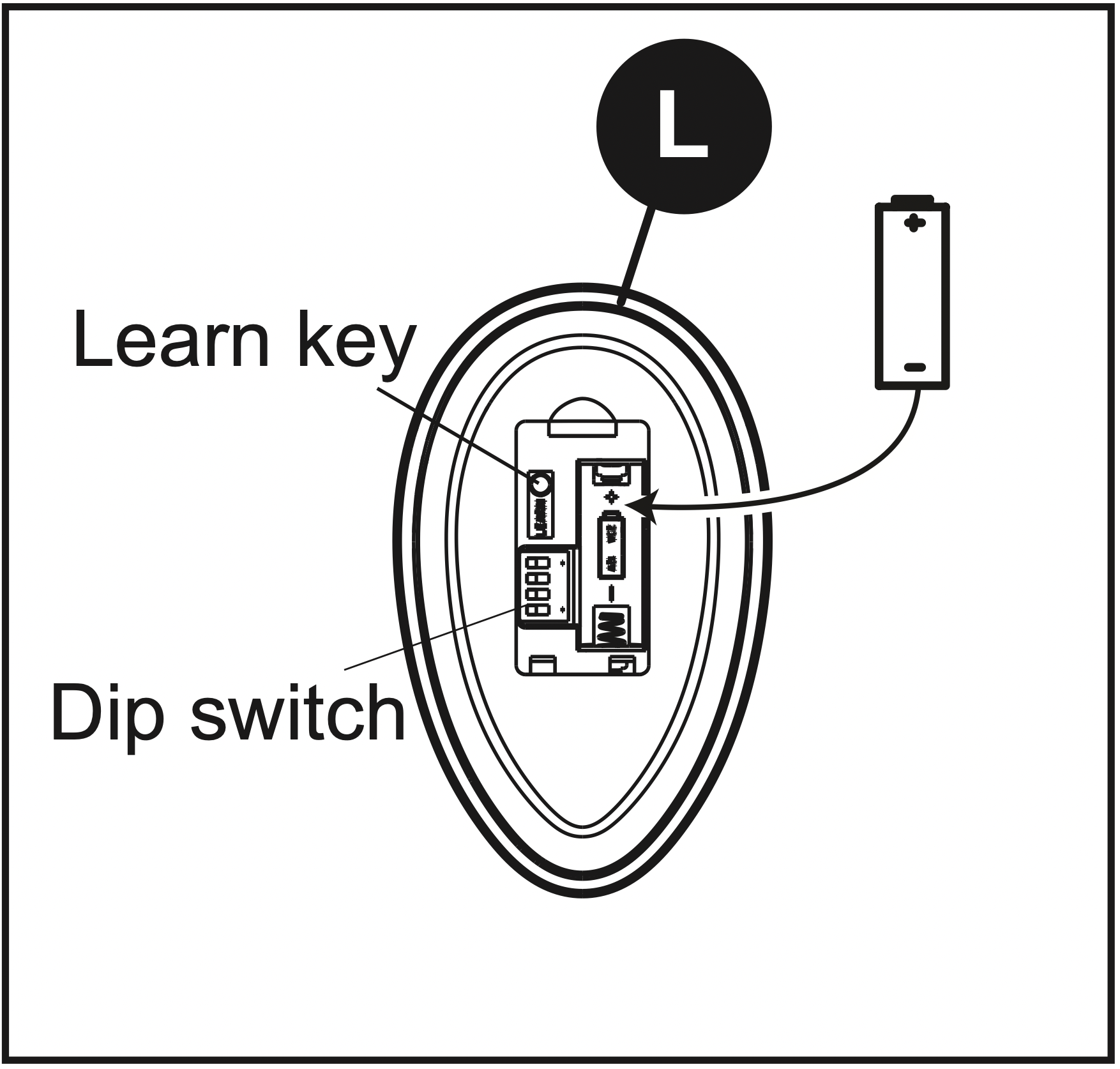
7. Insert receiver from the remote pack (L) into mounting bracket (A) with the flat side toward the ceiling. Connect the GREEN/GROUND wire from fan to the BARE/GROUNDED supply wire. Connect the BLACK wire (AC IN L) from the receiver to the supply BLACK wire. Connect the BLACK wire (TO MOTOR L) from the receiver to the BLACK wire from fan. Connect the WHITE wire (AC IN N) from receiver to the supply WHITE wire. Connect the WHITE wire (TO MOTOR N) from the receiver to the WHITE wire from fan. Connect the BLUE wire (FOR LIGHT) from receiver to the BLUE wire from fan.
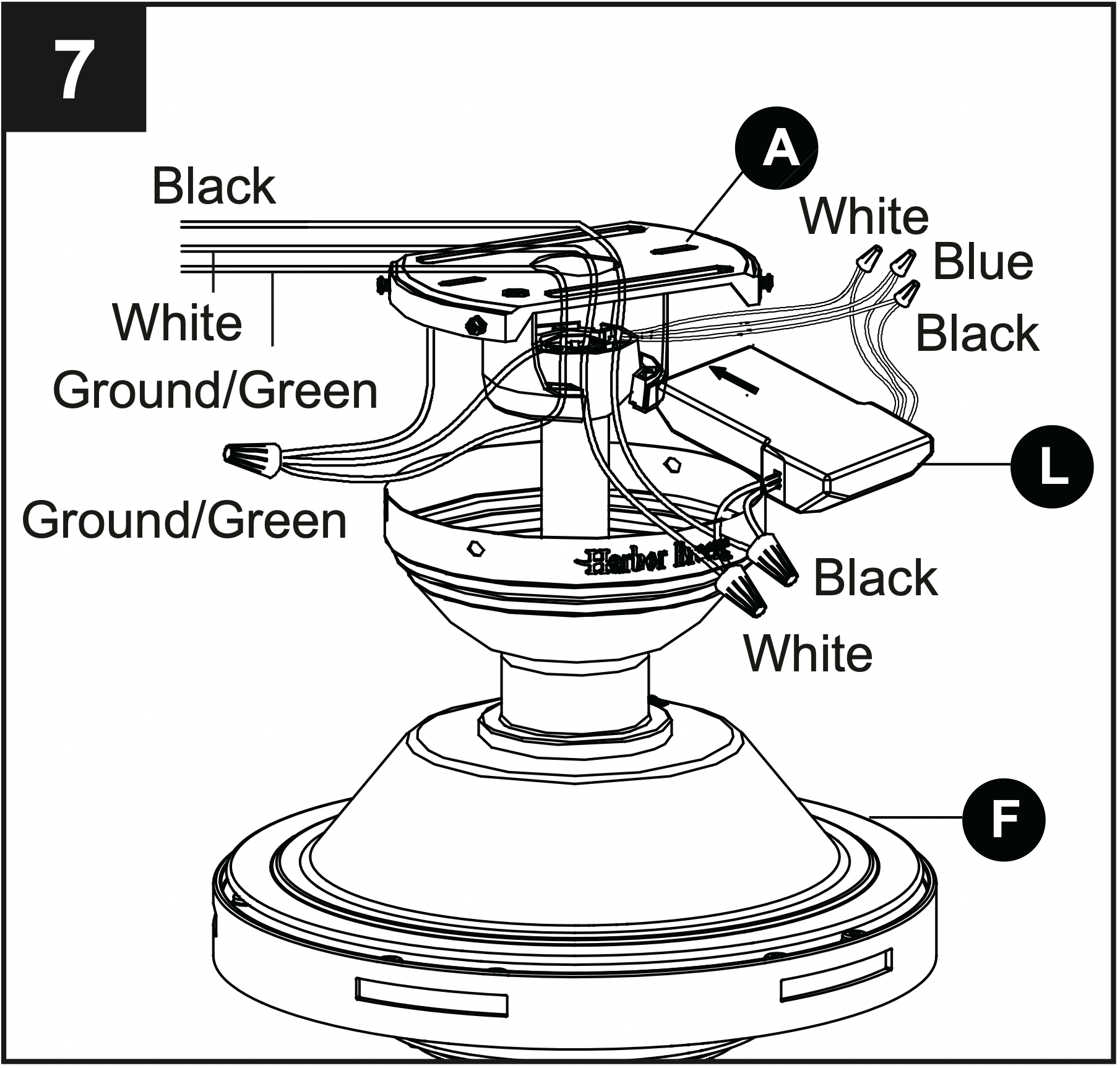
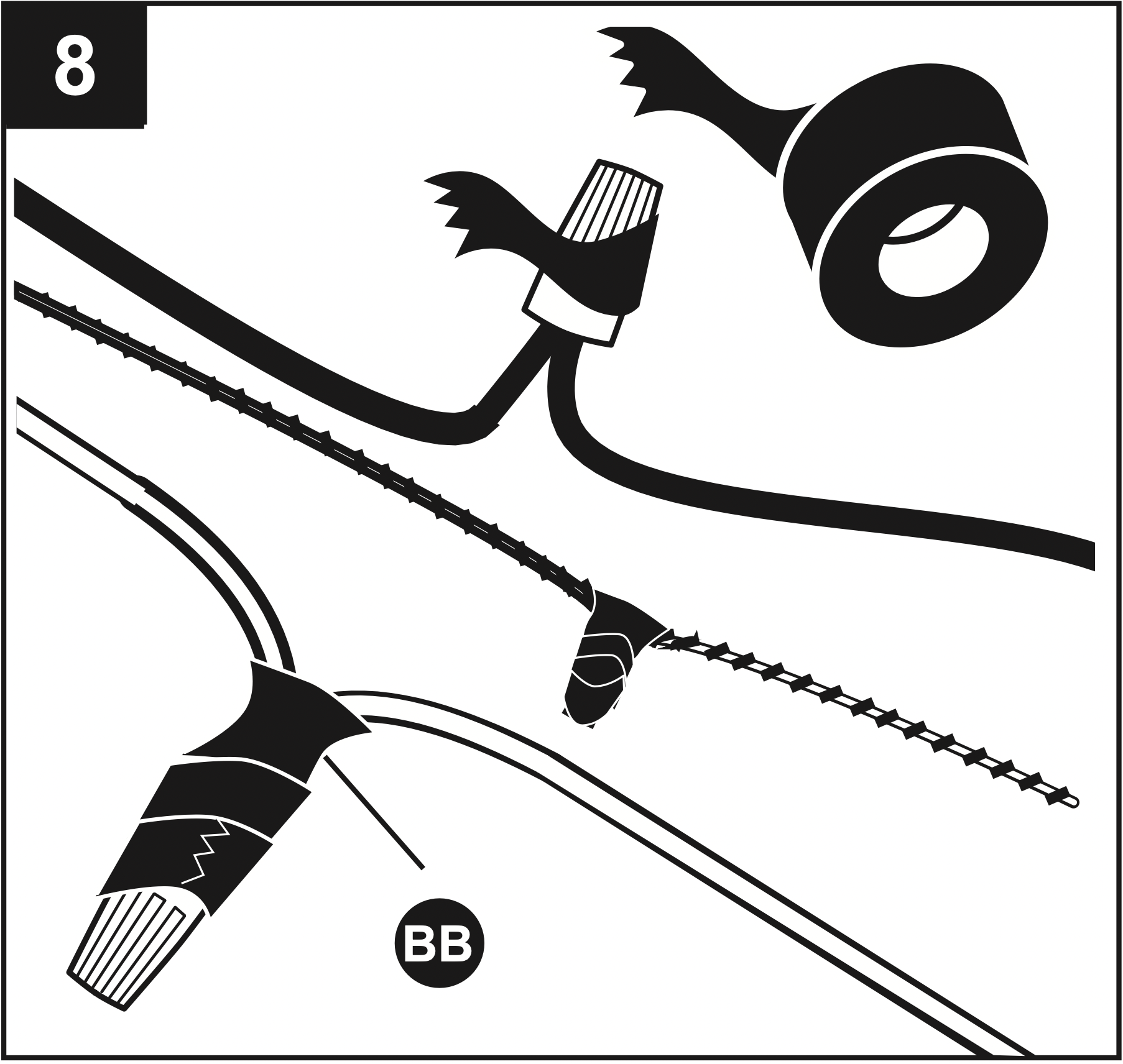
8. Twist wire ends together and screw wire connectors (BB) on in a clockwise direction. Tape wire connectors (BB) and wires together with electrical tape (not included).
WARNING: Be sure no bare wire or wire strands are visible after making connection. Place GREEN and WHITE connections on opposite side of box from the BLACK and BLUE (if applicable) connections. The splices should be turned upward and pushed carefully up into the outlet box.
Hardware Used

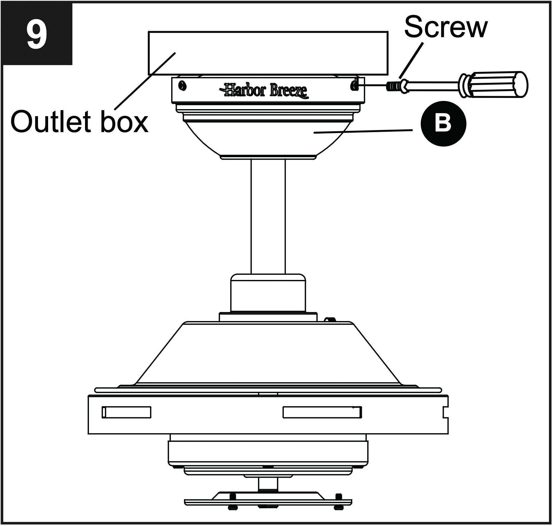
9. Slide the canopy (B) up to the ceiling and over the two screws on the mounting bracket (A). Rotate the canopy (B) to lock it in place, then secure with previously loosened/removed screws.
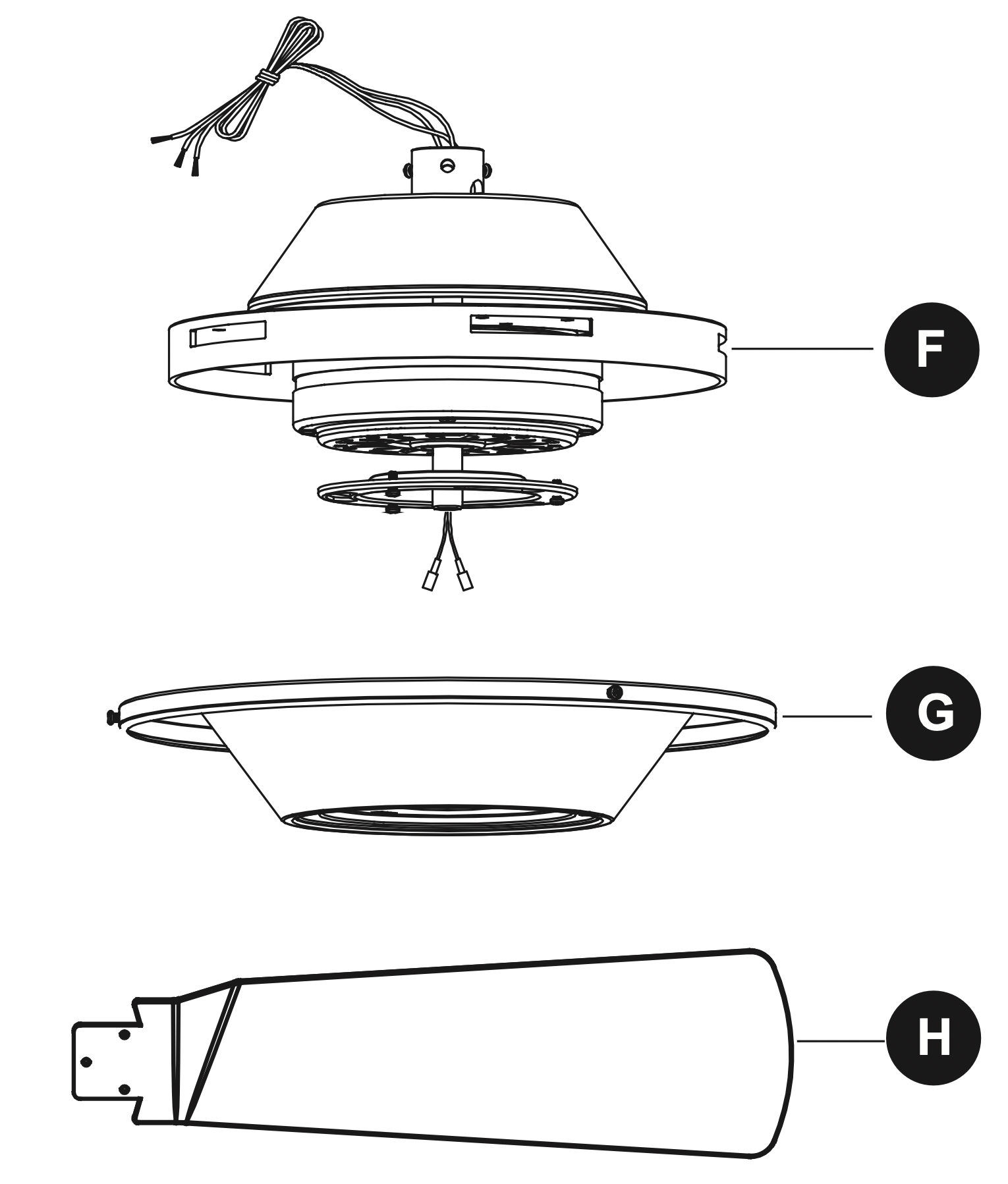
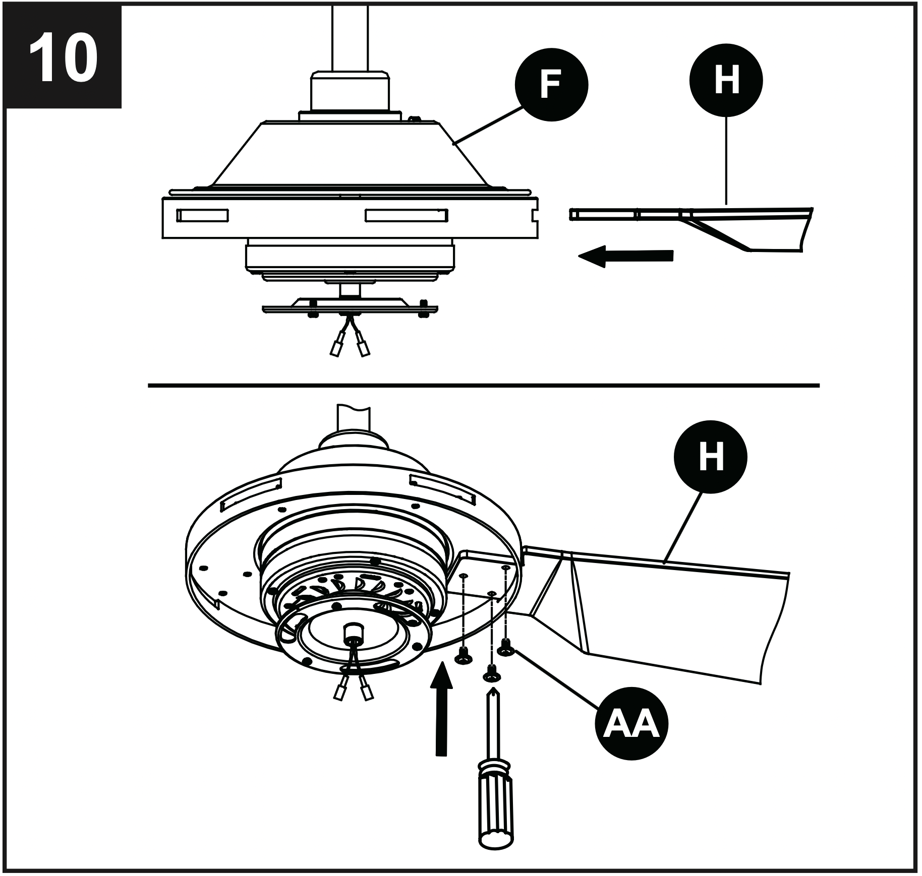
10. Insert blade (H) through the slot in the motor assembly (F), aligning the three screw holes in the blade (H) with the screw holes in the motor assembly (F). Secure blade (H) using blade screws (AA).
Repeat for the remaining blade assemblies.
Hardware Used

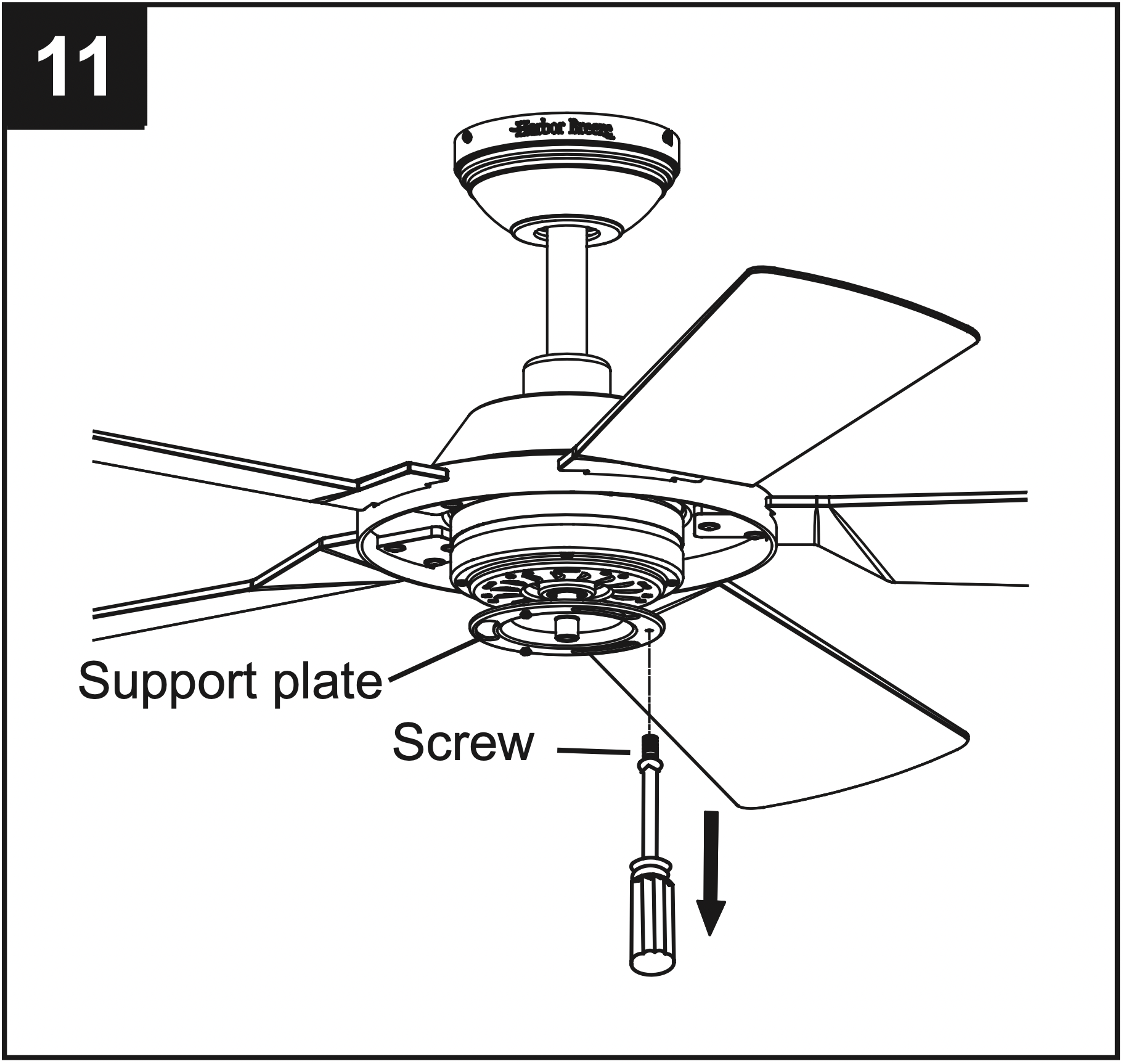
11. Remove one of the three screws from the support plate preassembled underneath the motor assembly (F). Loosen but do not remove the other two screws.
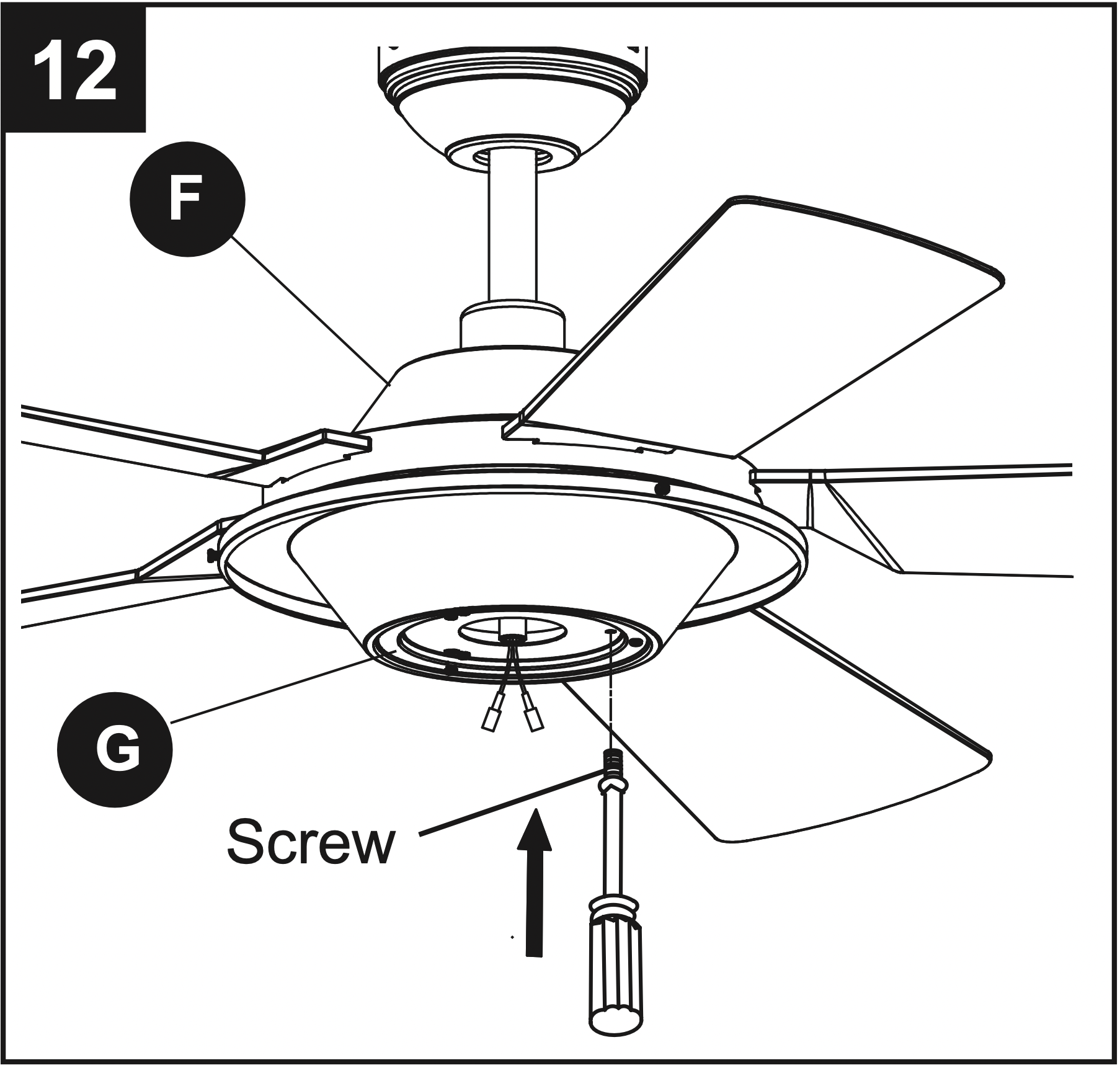
12. Pass the BLUE and WHITE wires from the motor assembly (F) through the center hole of the fitter plate (G). Align the two keyslots in the fitter plate (G) with the two screws in the support plate below the motor assembly (F). Place the fitter plate (G) over the two loosened screws and turn the fitter plate (G) clockwise until it locks. Re-install the previously removed screw, then tighten all screws securely.
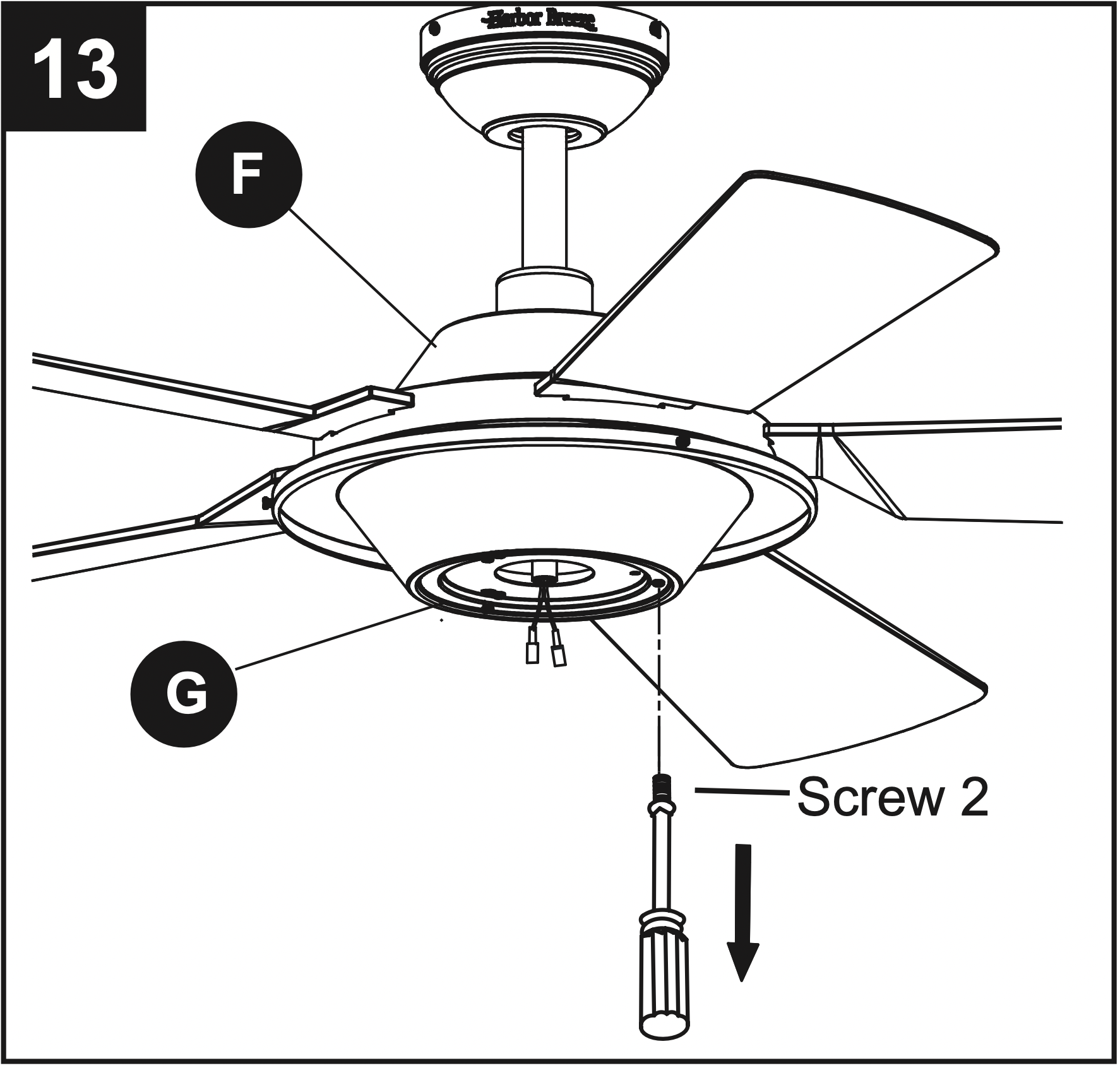
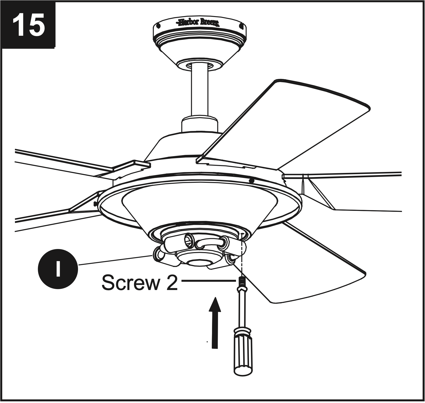
13. Remove one of the three screws from the fitter plate (G). Loosen but do not remove the other two screws.
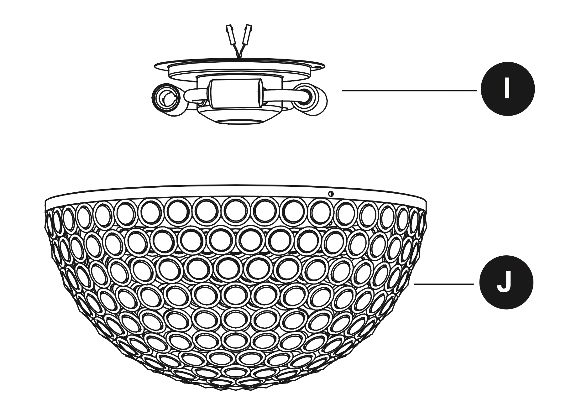
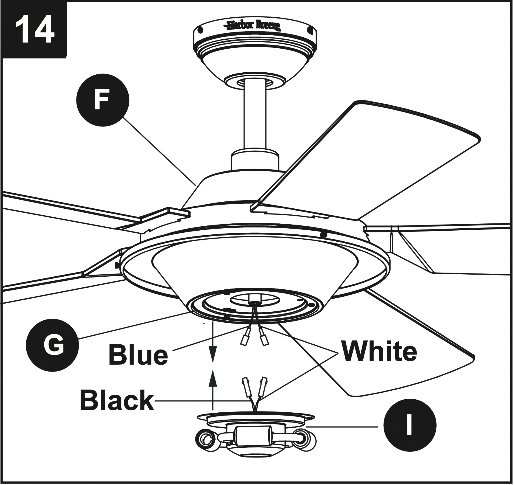
14. Connect the BLUE wire from the fan motor assembly (F) to the BLACK wire from the light fitter assembly (I) and connect the WHITE wire from the fan motor assembly (F) to the WHITE wire from the light fitter assembly (I) by connecting the plugs.
15. Align the two keyslots in the light fitter assembly (I) with the two loosened screws on the fitter plate (G). Place the light fitter assembly (I) over the two screws and turn the light fitter assembly (I) clockwise until it locks. Re-install the previously removed screw, then tighten all screws securely.
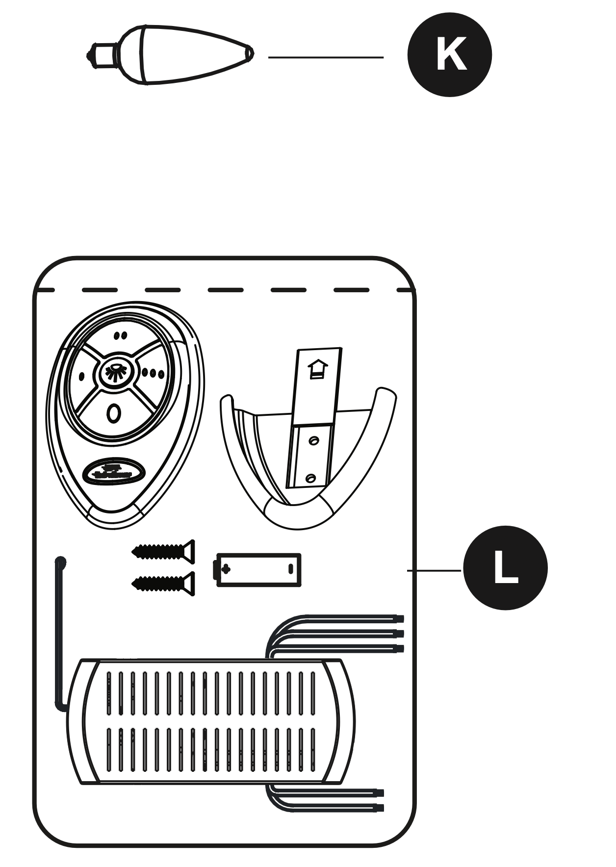
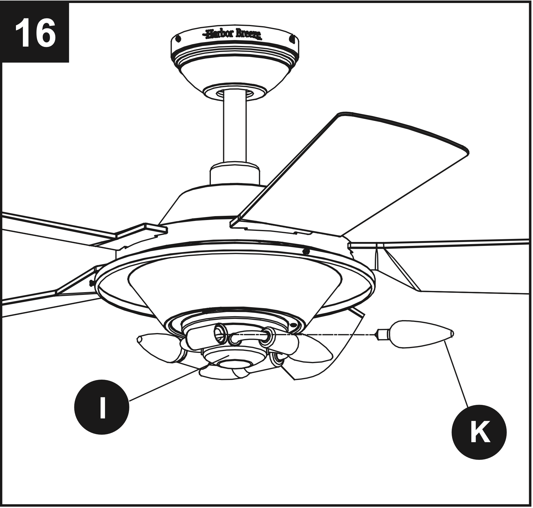
16. Install bulbs (K) to sockets on light fitter assembly (I).
IMPORTANT NOTE: Your fan has an energy-saving wattage limiter included. If you replace the bulbs with more than 190 watts, your fan will automatically turn off. Ensure bulb wattage is always less than 190 watts!
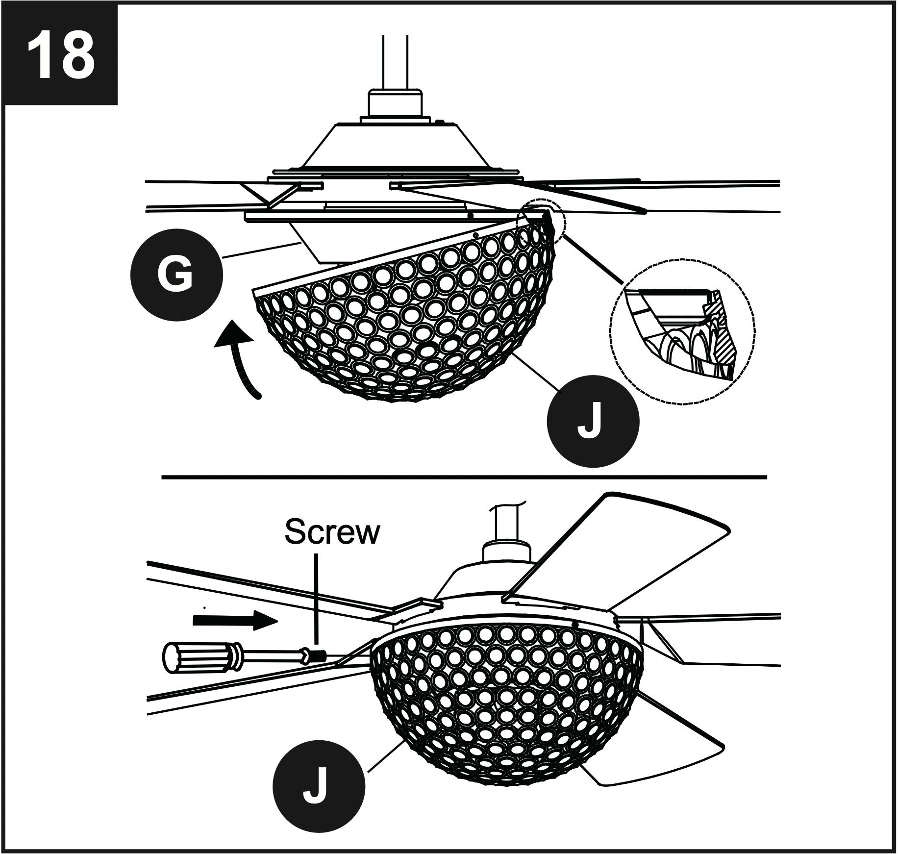
17. Remove three screws from the side of fitter plate (G) and save.
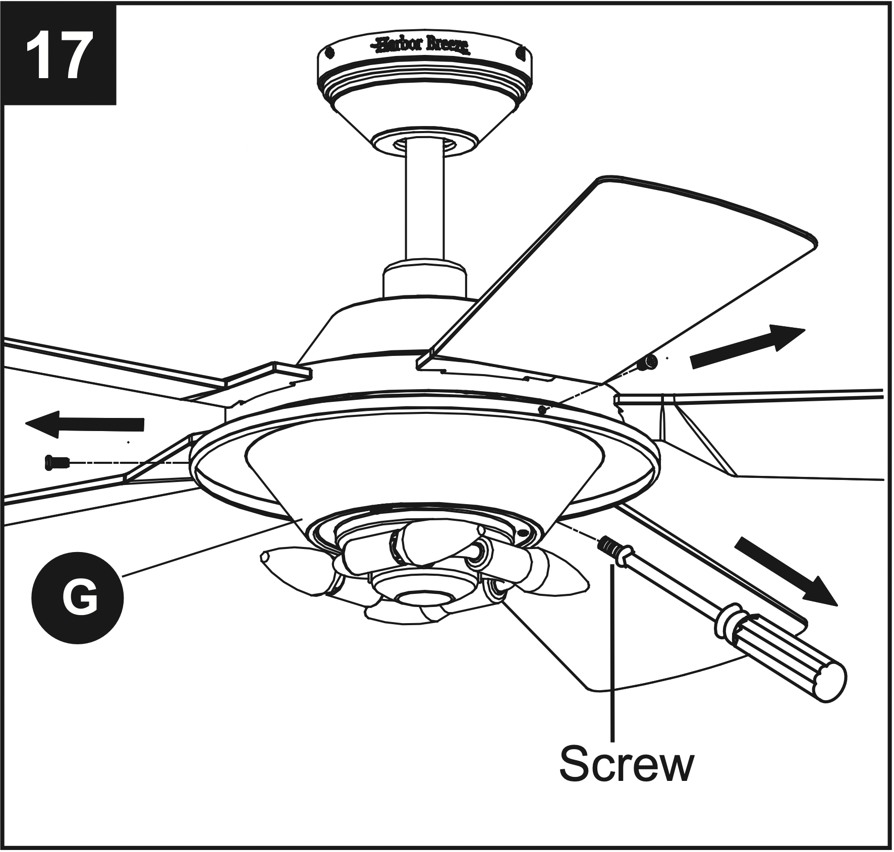
18. Hang the shade (J) by aligning the hook on the shade (J) with the hole on the fitter plate (G). Carefully push up the shade (J), aligning the screw holes in fitter plate (G) with shade (J). Re-install the three screws and tighten securely.
Note: If you have more than one remote controlled fan installed in the same location, you may want to change the frequency of the remote control to avoid any possible interference between remote controls. To change the frequency of the remote control, change the dip switch settings as described below:
1. REMOTE CONTROL:
(1) Install Battery/Learning Process:
Remove the battery cover from the back of the remote found in the remote pack (L). Insert the battery from the remote pack (L) into the remote; ensure polarity of battery matches the polarity indicated in the battery compartment -- positive (+) to positive (+) and negative (-) to negative (-). Replace the battery cover.
If you need to change the dip switches in the remote control due to a potential interference issue, slide the dip switches to your choice of either up or down -- the factory setting is up. Within 30 seconds of turning the fan’s power on, press and hold the “Learn” button on the remote control for 1 second. Once the receiver has detected the set frequency, the light of the fan will blink twice. Replace the battery cover. To confirm the remote control and receiver have paired successfully press any of the fan speed control buttons on the remote control.
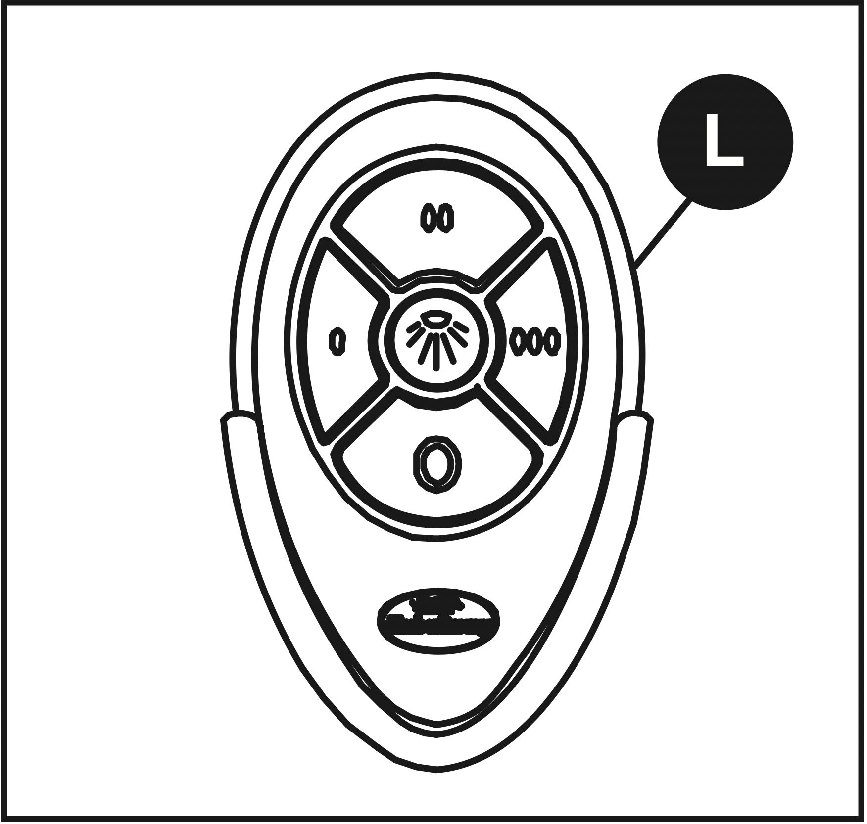
(2) Fan Control / Dimmer:
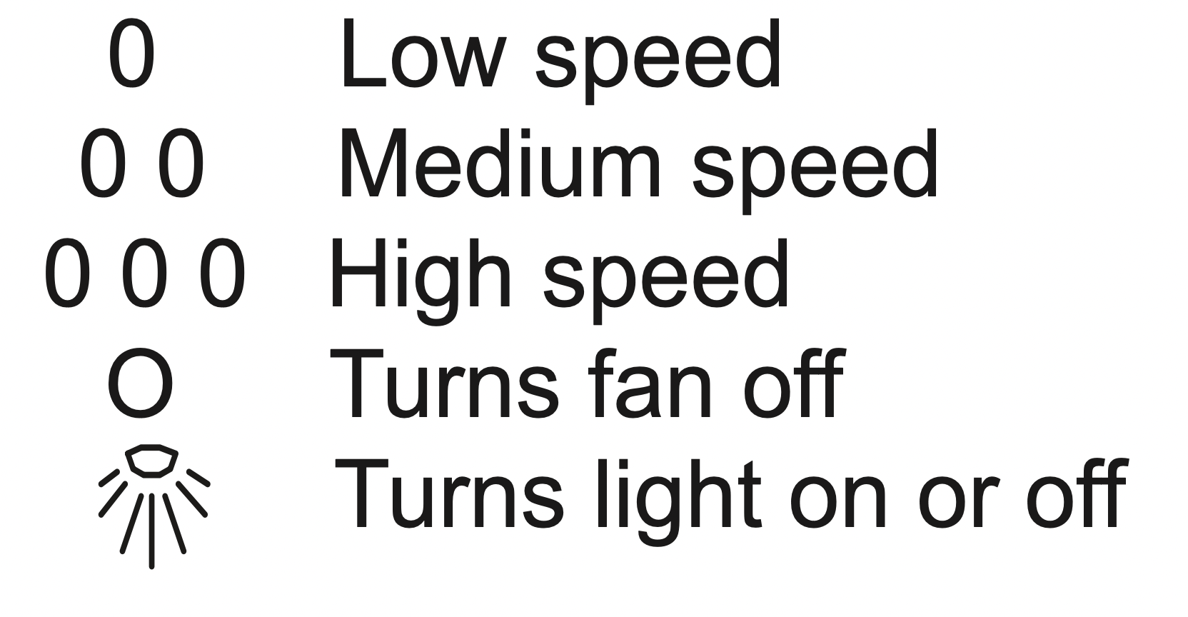
For the DIMMER function, press and hold the  button. Light will dim. Release the button when light is at desired level.
Note: This remote control has a memory function. The receiver stores the fan speed and light setting when the fan is turned off. When fan is turned on again, it starts with the most recent settings.
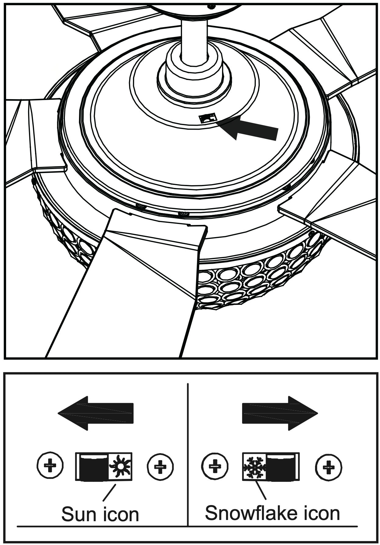
2. REVERSE SWITCH:
When the season changes, you may want to change the direction the fan blades spin. To switch between clockwise and counterclockwise rotation, flip the fan reversal switch.
WARNING: Wait for fan to stop before reversing switch.
- In warmer weather, counterclockwise rotation creates a downward airflow, which cools the air. Push the switch LEFT and see a Sun icon.
- In cooler weather, clockwise rotation creates an upward airflow, which moves hot air from the ceiling into the room. Push the switch RIGHT and see a Snowflake icon.
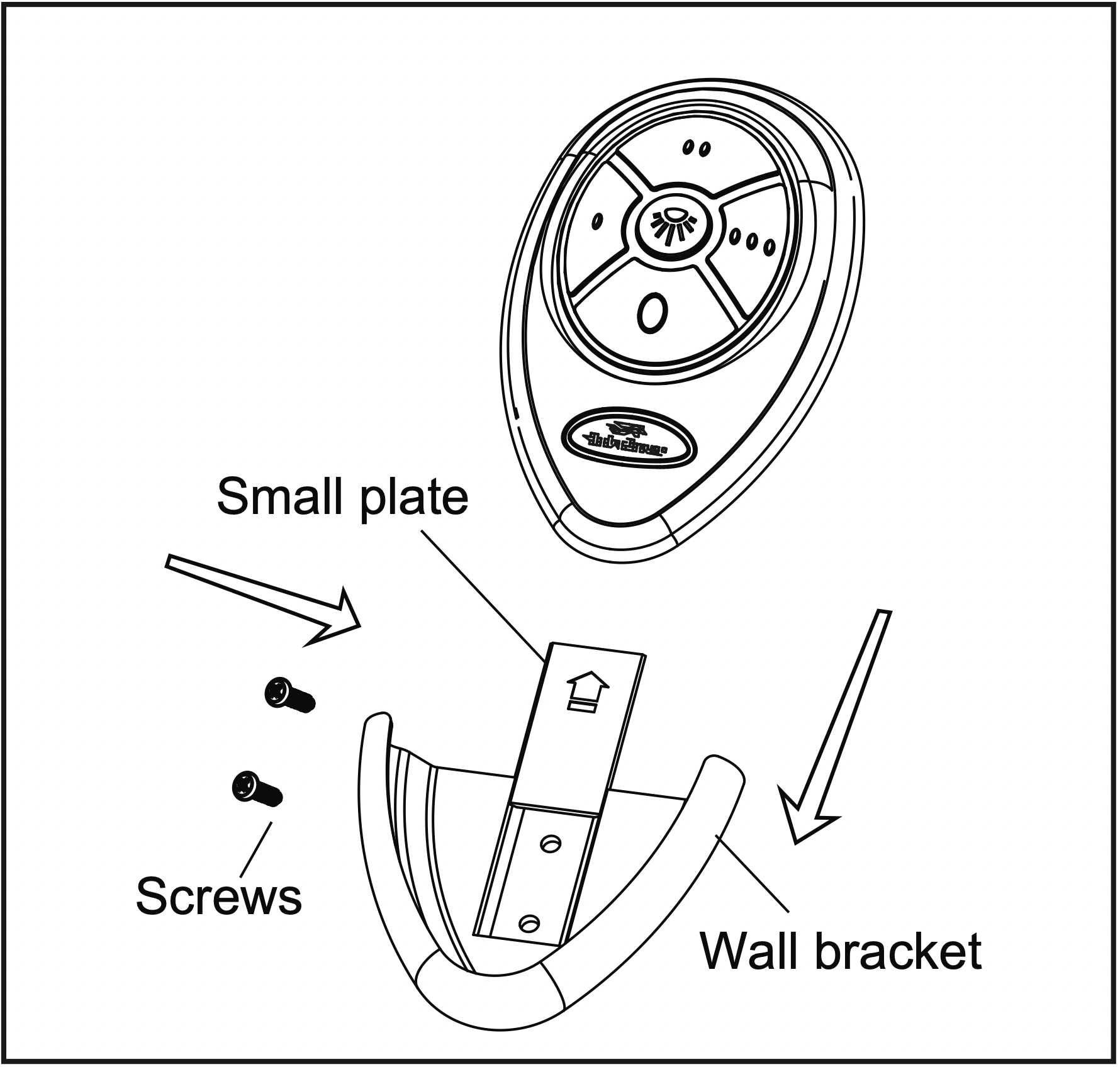
OPTIONAL: If desired, the wall bracket in remote pack (L) can be installed to house the remote control. Remove the small plate preassembled on the wall bracket and use the screws in remote pack (L) to secure the wall bracket at desired mounting location. Replace the small plate, then rest the remote control into wall bracket.
CARE AND MAINTENANCE
- IMPORTANT: Shut off main power supply before beginning any maintenance.
- DO NOT use water or a damp cloth to clean the ceiling fan.
- At least twice each year, tighten all screws and lower the canopy to check mounting bracket screws and downrod assembly.
- Clean fan housing with only a soft bristle brush or lint-free cloth to avoid scratching the finish. Clean blades with a lint-free cloth. You may occasionally apply a light coat of furniture polish to wood blades for added protection.
- Bulb replacement: Use 40-watt max. candelabra-base E12-type incandescent bulbs; CFLs and LEDs are not recommended for this item.
- Battery replacement: Use an A23 12-volt alkaline battery for the remote control.
TROUBLESHOOTING
| PROBLEM |
POSSIBLE CAUSE |
CORRECTIVE ACTION |
| Fan does not move. |
- Fan reversal switch not engaged.
- Battery is old or expired.
- Power is off or fuse is blown.
- Faulty wire connection.
|
- Push switch firmly either way.
- Use a new battery.
- Turn power on or check fuse.
- Turn power off. Loosen canopy, check all connections.
|
| Noisy operation. |
- Blades are loose.
- Cracked blade.
- Non-approved speed control.
|
- Tighten all blade screws.
- Replace blades (call customer service).
- Replace with an approved speed control device.
|
| Excessive wobbling. |
- Unbalanced blades.
- Blades are loose.
- Blade arms incorrectly attached.
- Fan not securely mounted.
- Fan too close to vaulted ceiling.
|
- Use blade balancing kit (sold seperately)
- Tighten all blade screws.
- Re-install blade arms.
- Turn power off. Carefully loosen canopy, remount securely.
- Lower or move fan. Extension downrods may be ordered (call customer service).
|
| Remote control malfunction. |
- No flash on transmitter LED.
- The remote control does not work.
|
- Check if the battery is installed into the remote control. Make sure the battery is installed properly. One side of the battery is positive and the other is negative.
- Sync the remote control to thereceiver following the steps described in step 1 on page 12. Make sure power to the fan is off before beginning the sync process.
|