Español p. 19
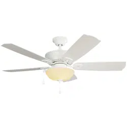
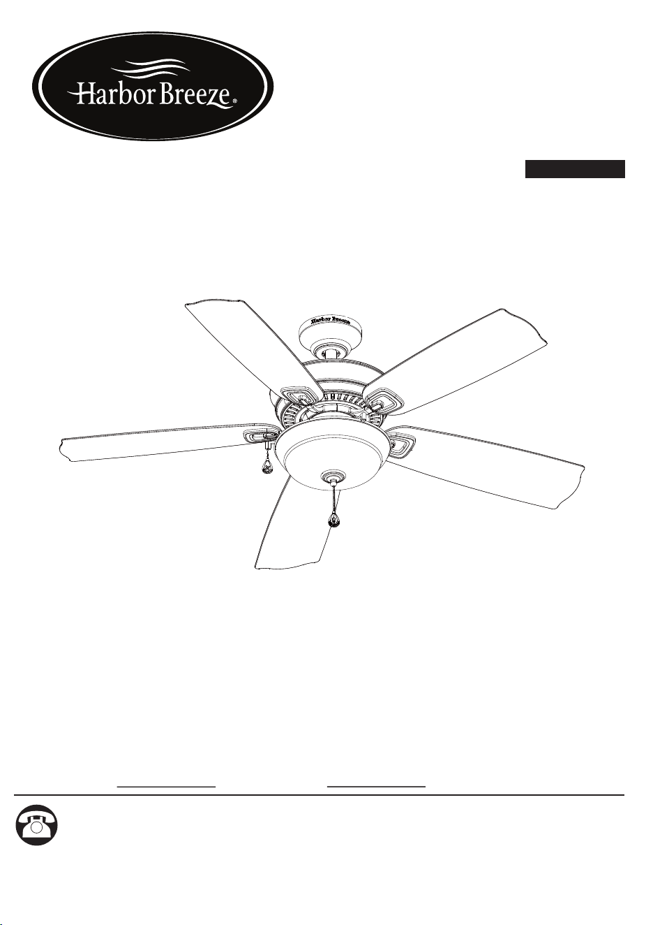
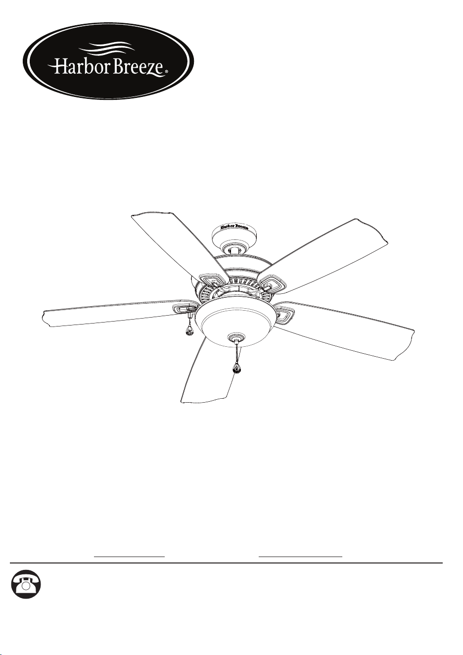
ECHOLAKE
CEILING FAN
ITEM #0747603, 0747604
MODEL #00894, 00893
Serial Number Purchase Date
Harbor Breeze
®
is a registered trademark of LF,
LLC. All Rights Reserved.
Questions, problems, missing parts? Before returning to your retailer,
call our customer service department at 1-800-643-0067, 8 a.m. - 6 p.m., EST,
Monday - Thursday 8 a.m. - 5 p.m., EST Friday
PH18308
ATTACH YOUR RECEIPT HERE
UL MODEL #52-GV
1

TABLE OF CONTENTS
Package Contents...................................................................................................... 3
Hardware Contents..................................................................................................... 4
Preparation ............................................................................................................... 4
Safety Information....................................................................................................... 5
Assembly or Installation Instructions .......................................................................... 6
Operating Instructions ............................................................................................... 16
Care and Maintenance ............................................................................................. 17
Troubleshooting......................................................................................................... 17
Warranty..................................................................................................................................18
Replacement Parts List ............................................................................................. 18
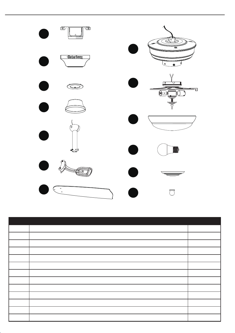
PACKAGE CONTENTS
PART DESCRIPTION QUANTITY
A Mounting Bracket (preassembled to canopy (B)) 1
B Canopy 1
C Canopy Cover (preassembled to canopy (B)) 1
D Yoke Cover 1
E Downrod Assembly 1
F Blade Bracket 5
G Blade 5
H Motor Housing 1
I Light Kit 1
J Glass Bowl 1
K Bulb 2
L Bowl Cap (preassembled to light kit (I)) 1
M Finial (preassembled to light kit (I)) 1
K
F
A
I
H
G
D
C
B
E
J
L
M
M
32
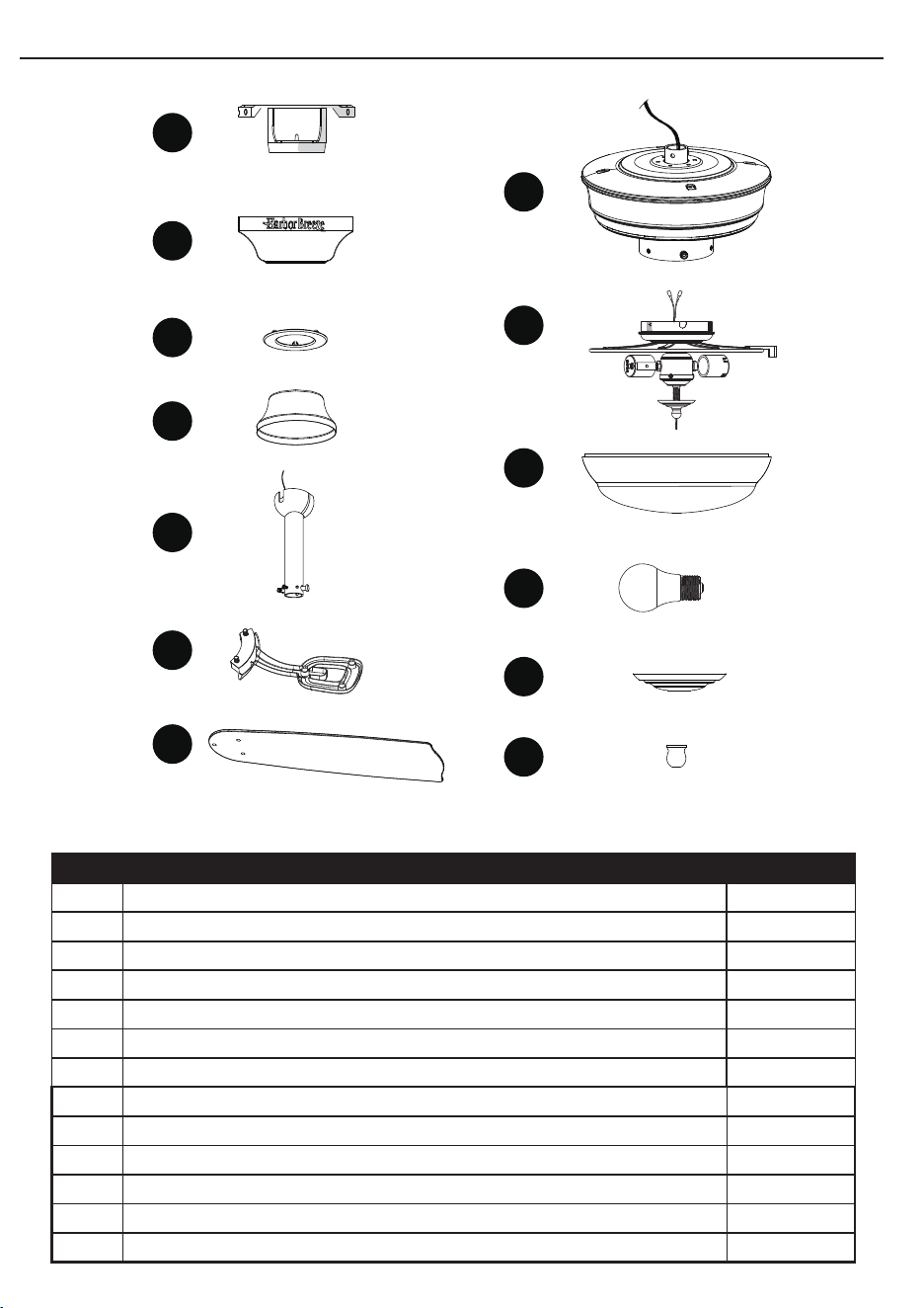
TABLE OF CONTENTS
Package Contents...................................................................................................... 3
Hardware Contents..................................................................................................... 4
Preparation ............................................................................................................... 4
Safety Information....................................................................................................... 5
Assembly or Installation Instructions .......................................................................... 6
Operating Instructions ............................................................................................... 16
Care and Maintenance ............................................................................................. 17
Troubleshooting......................................................................................................... 17
Warranty..................................................................................................................................18
Replacement Parts List ............................................................................................. 18
PACKAGE CONTENTS
PART DESCRIPTION QUANTITY
A Mounting Bracket (preassembled to canopy (B)) 1
B Canopy 1
C Canopy Cover (preassembled to canopy (B)) 1
D Yoke Cover 1
E Downrod Assembly 1
F Blade Bracket 5
G Blade 5
H Motor Housing 1
I Light Kit 1
J Glass Bowl 1
K Bulb 2
L Bowl Cap (preassembled to light kit (I)) 1
M Finial (preassembled to light kit (I)) 1
K
F
A
I
H
G
D
C
B
E
J
L
M
M
32
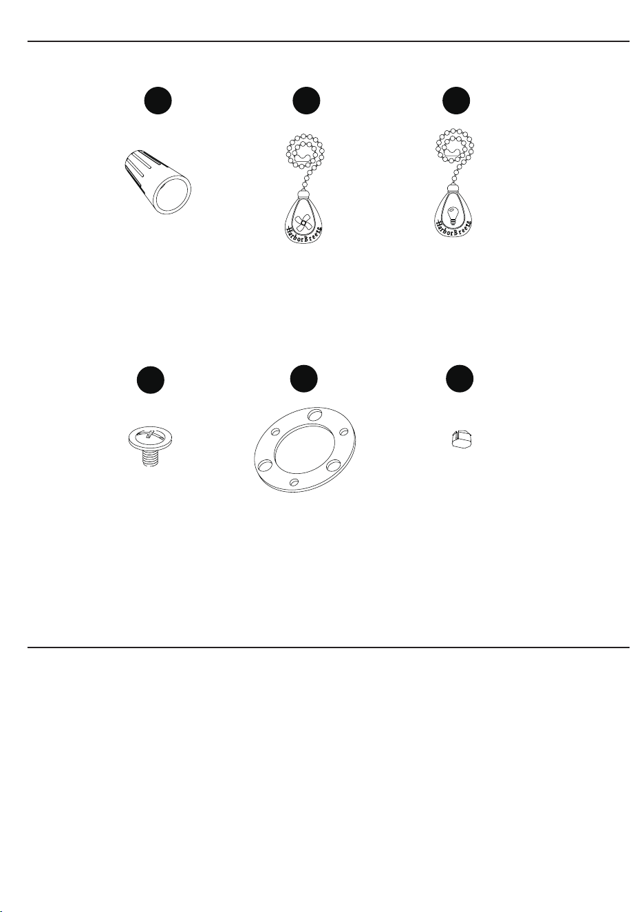
HARDWARE CONTENTS
SAFETY INFORMATION
READ AND SAVE THESE INSTRUCTIONS
Please read and understand this entire manual before attempting to assemble, operate
or install the product.
• When using an existing outlet box, be sure the box is securely attached to the
building structure and can support the full weight of the fan, so to avoid potential
serious injury or death.
• All wiring must be in accordance with the National Electrical Code “ANSI/NFPA 70”
and local electrical codes. Electrical installation should be performed by a qualied
licensed electrician.
• DO NOT use bulbs with wattage greater than the maximum value stated on the
xture and in this manual. Using a higher wattage bulb than specied will increase
xture temperature and cause risk of re.
• Disconnect the electrical supply circuit to the fan before installing kit.
• Electrical diagrams are for reference only.
• The net weight of this fan including the light kit is: 21.5 lbs.
WARNING
• FIRE, ELECTRIC SHOCK OR PERSONAL INJURY HAZARD - To reduce the
risk of re, electric shock, or personal injury, mount to an outlet box marked
“ACCEPTABLE FOR FAN SUPPORT OF 35.1 lbs OR LESS” and use the mounting
screws provided with the outlet box. Most outlet boxes commonly used for the
support of lighting xtures are not acceptable for fan support and may need to be
replaced. Consult a qualied licensed electrician if in doubt.
CAUTION
• PERSONAL INJURY HAZARD - To reduce the risk of personal injury, do not bend
the blade brackets when installing the brackets, balancing the blades, or cleaning
the fan. DO NOT insert foreign objects in between the rotating fan blades.
54
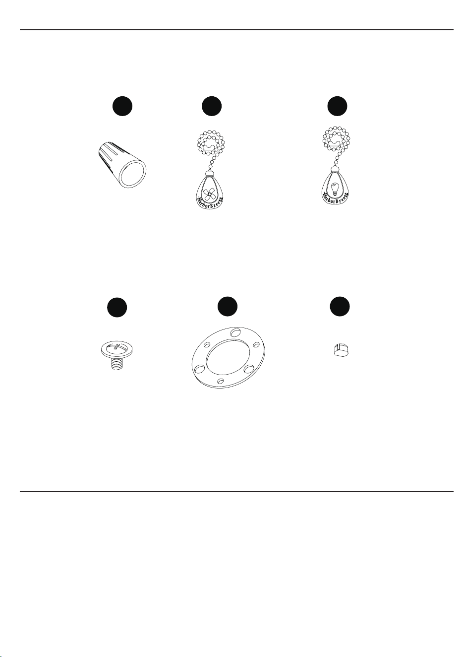
AA
BB
CC
DD
EE
FF
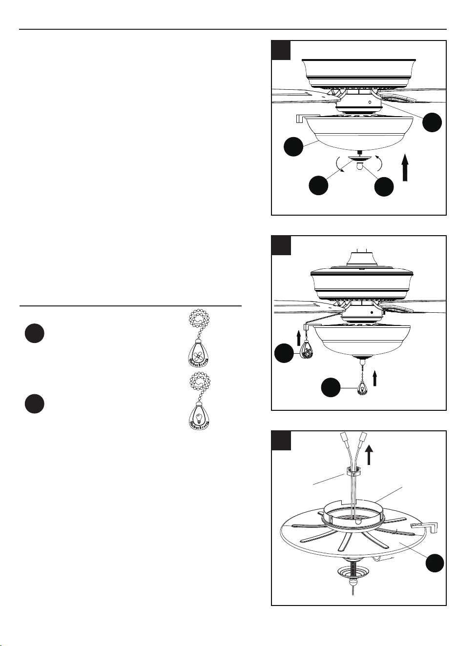
Fan Pull Chain
Extension
Qty. 1
(NOT TO SCALE)
Light Pull Chain
Extension
Qty. 1
(NOT TO SCALE)
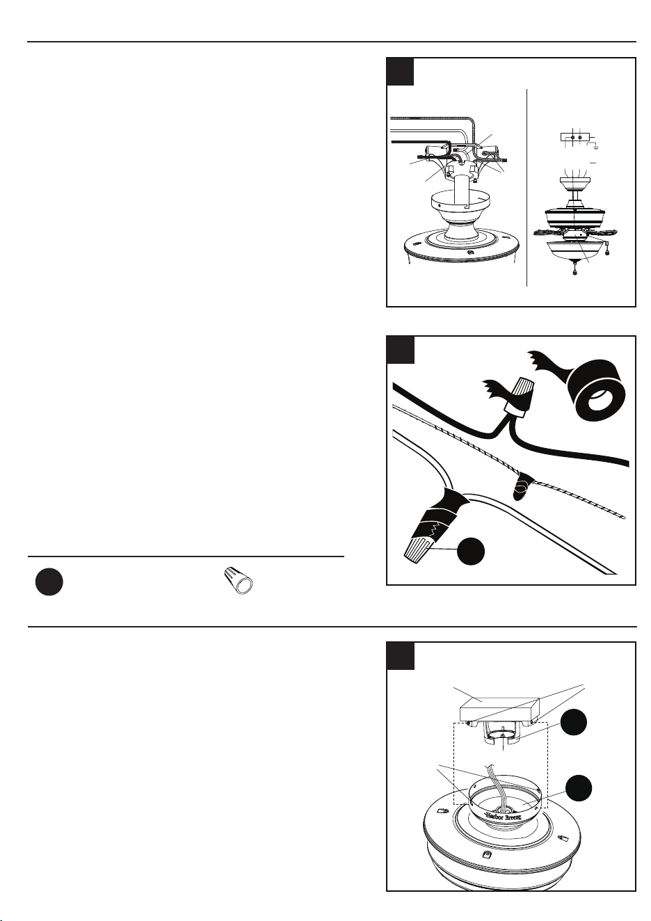
Wire Connector
Qty. 4
Blade Screw
Qty. 16
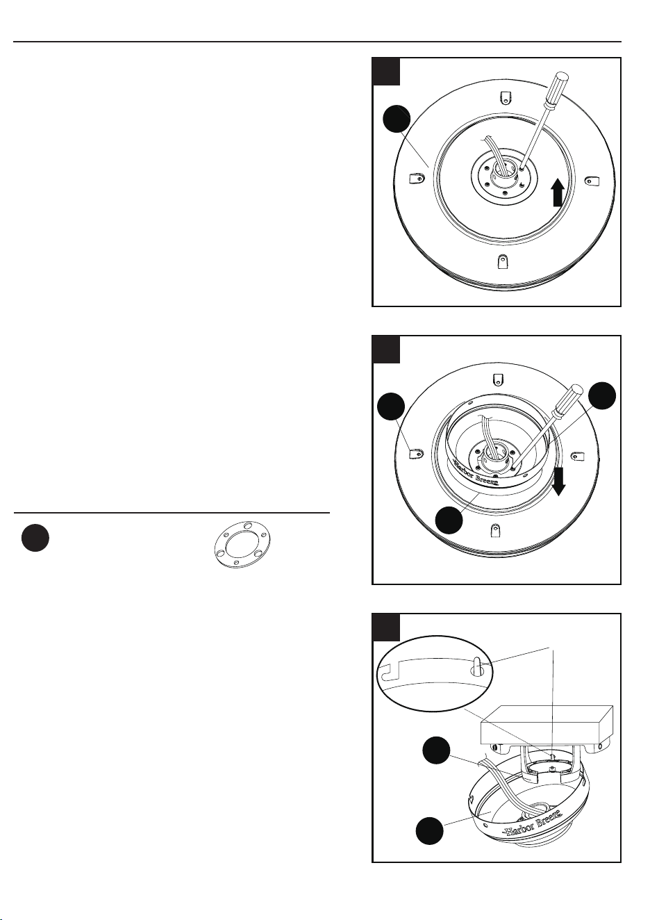
Plug
Qty. 1
Rubber Gasket
Qty. 1
(NOT TO SCALE)
PREPARATION
Before beginning assembly of product, make sure all parts are present. Compare parts
with package contents list and hardware contents list. If any part is missing or damaged,
do not attempt to assemble the product.
Estimated Assembly Time: 45 minutes.
Tools Required for Assembly (not included): Phillips screwdriver, step ladder, electrical
tape, pliers, wire cutters, wire strippers.
Helpful Tools (not included): Electrical circuit tester.

HARDWARE CONTENTS
SAFETY INFORMATION
READ AND SAVE THESE INSTRUCTIONS
Please read and understand this entire manual before attempting to assemble, operate
or install the product.
• When using an existing outlet box, be sure the box is securely attached to the
building structure and can support the full weight of the fan, so to avoid potential
serious injury or death.
• All wiring must be in accordance with the National Electrical Code “ANSI/NFPA 70”
and local electrical codes. Electrical installation should be performed by a qualied
licensed electrician.
• DO NOT use bulbs with wattage greater than the maximum value stated on the
xture and in this manual. Using a higher wattage bulb than specied will increase
xture temperature and cause risk of re.
• Disconnect the electrical supply circuit to the fan before installing kit.
• Electrical diagrams are for reference only.
• The net weight of this fan including the light kit is: 21.5 lbs.
WARNING
• FIRE, ELECTRIC SHOCK OR PERSONAL INJURY HAZARD - To reduce the
risk of re, electric shock, or personal injury, mount to an outlet box marked
“ACCEPTABLE FOR FAN SUPPORT OF 35.1 lbs OR LESS” and use the mounting
screws provided with the outlet box. Most outlet boxes commonly used for the
support of lighting xtures are not acceptable for fan support and may need to be
replaced. Consult a qualied licensed electrician if in doubt.
CAUTION
• PERSONAL INJURY HAZARD - To reduce the risk of personal injury, do not bend
the blade brackets when installing the brackets, balancing the blades, or cleaning
the fan. DO NOT insert foreign objects in between the rotating fan blades.
54
AA
BB
CC
DD
EE
FF
Fan Pull Chain
Extension
Qty. 1
(NOT TO SCALE)
Light Pull Chain
Extension
Qty. 1
(NOT TO SCALE)
Wire Connector
Qty. 4
Blade Screw
Qty. 16
Plug
Qty. 1
Rubber Gasket
Qty. 1
(NOT TO SCALE)
PREPARATION
Before beginning assembly of product, make sure all parts are present. Compare parts
with package contents list and hardware contents list. If any part is missing or damaged,
do not attempt to assemble the product.
Estimated Assembly Time: 45 minutes.
Tools Required for Assembly (not included): Phillips screwdriver, step ladder, electrical
tape, pliers, wire cutters, wire strippers.
Helpful Tools (not included): Electrical circuit tester.

ASSEMBLY INSTRUCTIONS
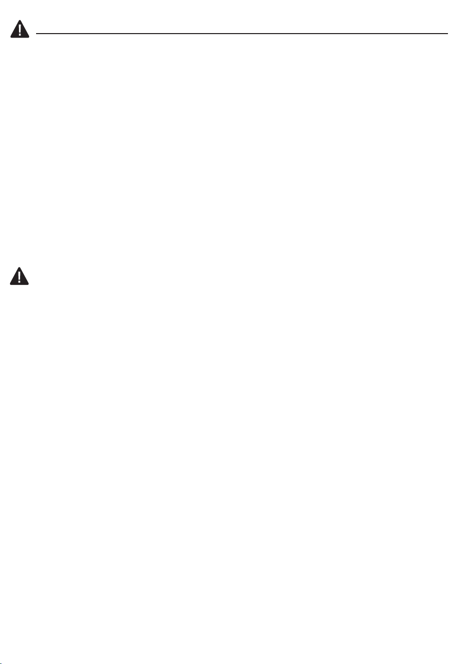
1. Determine mounting method to use.
A - Downrod Mount (standard or angled ceiling)
B - Closemount (normal ceiling only)
IMPORTANT: lf using the angle mount, check
to make sure the ceiling angle is not steeper
than 20°.
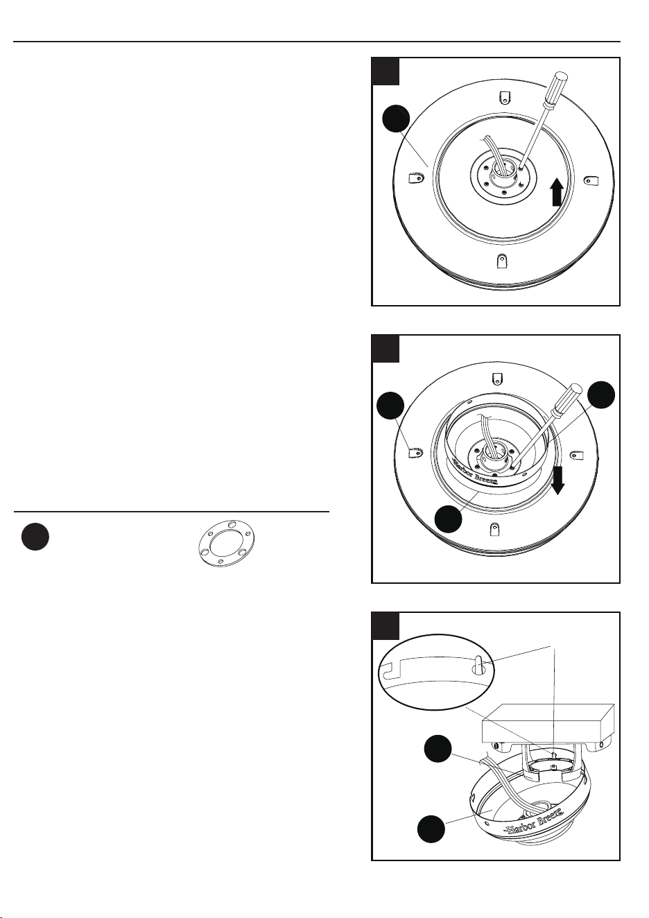
2. Remove and discard the ve rubber inserts
and ve mounting screws from the underside
of the motor housing (H).
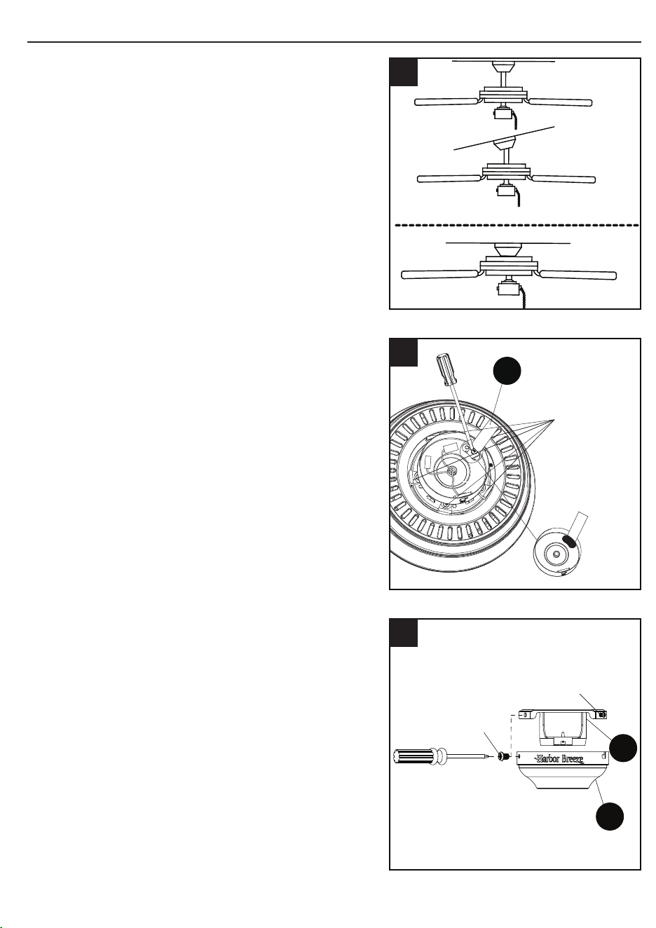
3. Remove the mounting bracket (A) from the
canopy (B) by loosening the four screws
on the top of the canopy (B). Remove the
two non-slotted screws and save.
76
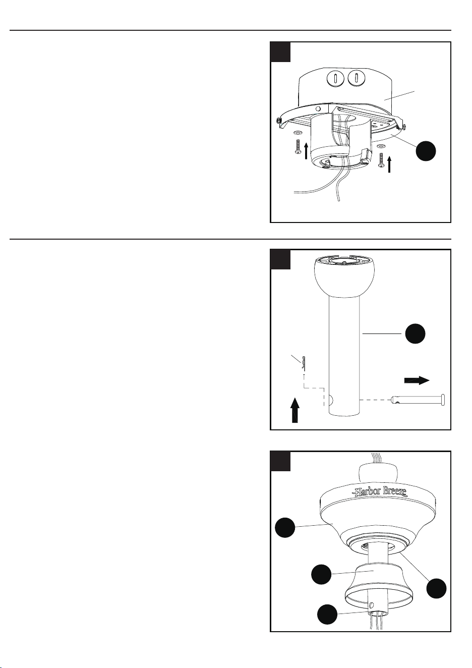
4. Install the mounting bracket (A) to the
outlet box (not included) using the two
screws provided with the outlet box.
Securely tighten the two screws.
A
B
1
Outlet box
A
4
Clip
Pin
E
1
C
B
D
E
2
Rubber
insert
and screw
H
Waterproof
rubber plug
2
A
B
Remove
and save
Loosen but
do not remove
3
ASSEMBLY INSTRUCTIONS
DOWNROD STYLE FAN MOUNTING
NOTE: The switch cup has an access hole
that is sealed with a waterproof rubber
plug. Remove and save the rubber plug to
allow the screwdriver to reach the mounting
screws in the motor housing. The rubber
plug will be reinserted after the blade
brackets have been installed.
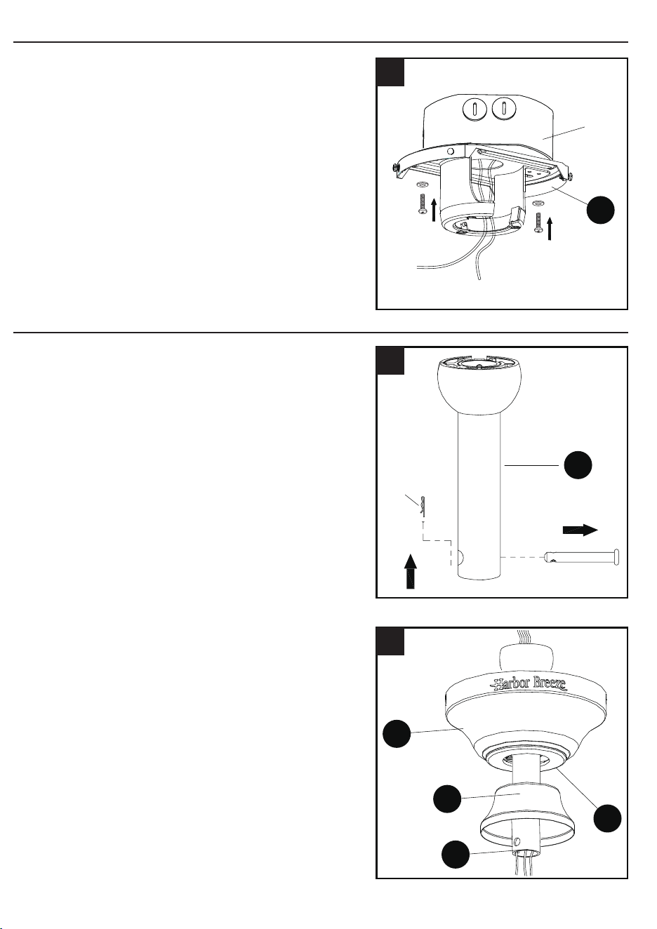
1. Remove pin and clip from downrod assembly
(E) and save.
2. Insert downrod assembly (E) through
canopy (B), canopy cover (C) and yoke
cover (D). Thread wires from the motor
housing (H) through downrod assembly (E).
Follow mounting instructions for Downrod
Style Fan Mounting on page 7 or Closemount
Style Fan Mounting on page 8, depending on
mounting method (A or B) chosen in step 1 on
page 6.
ASSEMBLY INSTRUCTIONS
1. Determine mounting method to use.
A - Downrod Mount (standard or angled ceiling)
B - Closemount (normal ceiling only)
IMPORTANT: lf using the angle mount, check
to make sure the ceiling angle is not steeper
than 20°.
2. Remove and discard the ve rubber inserts
and ve mounting screws from the underside
of the motor housing (H).
3. Remove the mounting bracket (A) from the
canopy (B) by loosening the four screws
on the top of the canopy (B). Remove the
two non-slotted screws and save.
76
4. Install the mounting bracket (A) to the
outlet box (not included) using the two
screws provided with the outlet box.
Securely tighten the two screws.
A
B
1
Outlet box
A
4
Clip
Pin
E
1
C
B
D
E
2
Rubber
insert
and screw
H
Waterproof
rubber plug
2
A
B
Remove
and save
Loosen but
do not remove
3
ASSEMBLY INSTRUCTIONS
DOWNROD STYLE FAN MOUNTING
NOTE: The switch cup has an access hole
that is sealed with a waterproof rubber
plug. Remove and save the rubber plug to
allow the screwdriver to reach the mounting
screws in the motor housing. The rubber
plug will be reinserted after the blade
brackets have been installed.
1. Remove pin and clip from downrod assembly
(E) and save.
2. Insert downrod assembly (E) through
canopy (B), canopy cover (C) and yoke
cover (D). Thread wires from the motor
housing (H) through downrod assembly (E).
Follow mounting instructions for Downrod
Style Fan Mounting on page 7 or Closemount
Style Fan Mounting on page 8, depending on
mounting method (A or B) chosen in step 1 on
page 6.
98
DOWNROD STYLE FAN MOUNTING
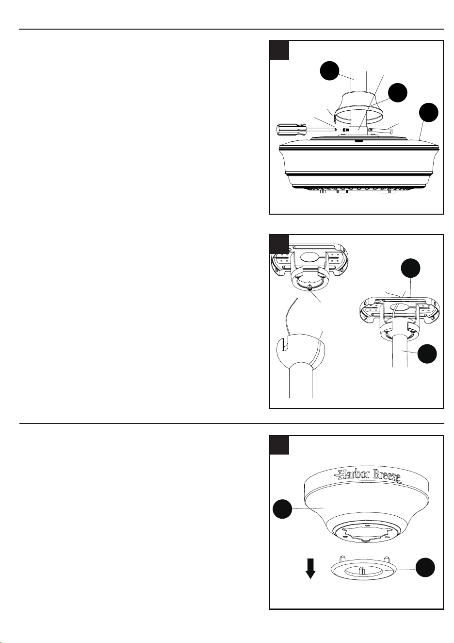
3. Loosen the two set screws from the yoke. Slip
downrod assembly (E) into yoke, aligning holes
in downrod assembly (E) and yoke. Insert the
pin through yoke and downrod assembly (E),
then insert clip into pin until it snaps into place.
Tighten set screws. Slide the yoke cover (D)
down over the motor housing (H).
4. Install hanger ball on the top of downrod
assembly (E) into mounting bracket (A)
opening. Rotate fan until slot on hanger ball
engages the tab on the mounting bracket (A).
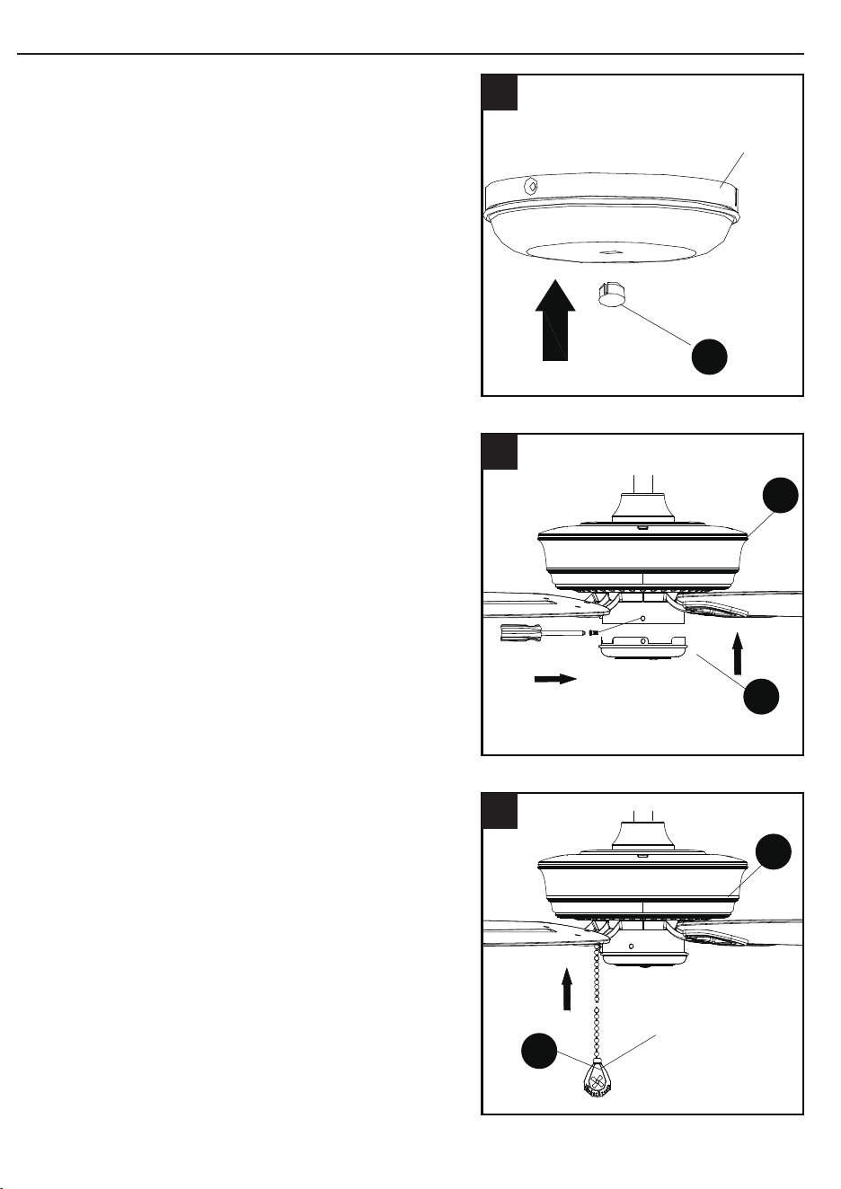
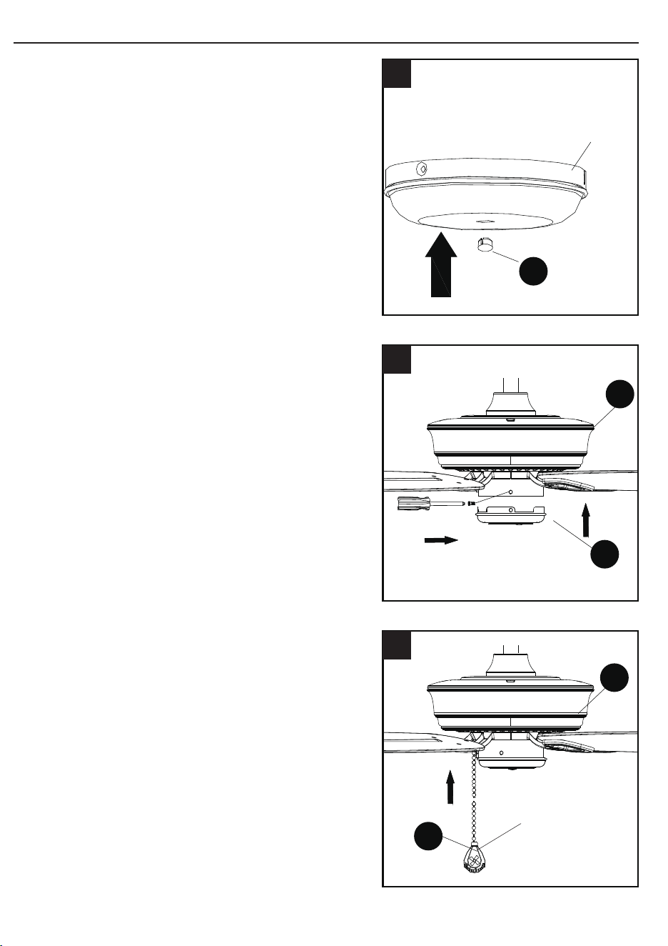
1. Remove the canopy cover (C) from the
bottom of the canopy (B).
Clip
Pin
Set screw
Yoke
E
D
H
3
Slot
Tab
A
E
4
B
C
1
DANGER: Be careful when aligning the tab
to the slot! If not fully engaged, there is a
possibility of fan falling, which may result in
serious injury or death.
CLOSEMOUNT STYLE FAN MOUNTING
CLOSEMOUNT STYLE FAN MOUNTING
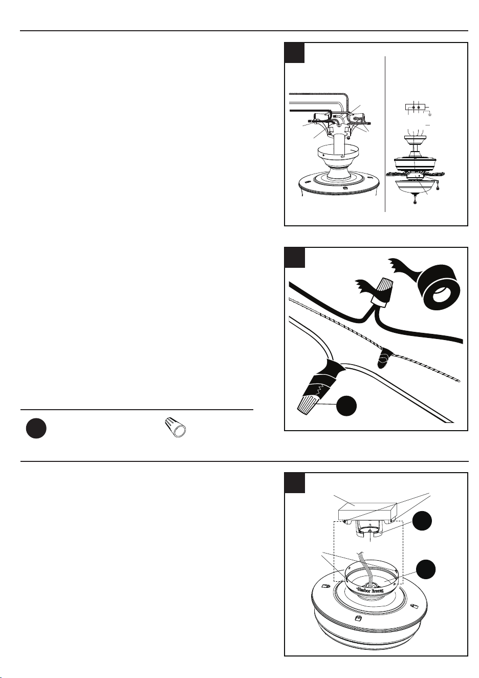
2. Remove three of the six screws and
lockwashers (every other one) securing the
motor collar to the top of the fan motor housing
and save.
3. Place the rubber gasket (EE) over the
remaining screws on motor housing (H).
Pull wires through hole in canopy (B), and
attach canopy (B) to motor housing (H) using
the three screws removed in previous step.
Tighten the screws securely.
4. Temporarily hang the canopy (B) onto the
hook on the mounting bracket (A) using
one of the non-slotted holes in the canopy
(B). This will allow for hands-free wiring.
H
2
H
B
EE
3
B
A
Hook
4
You may now proceed to WIRING page 10.
Hardware Used
Rubber gasket x 1
EE
98
DOWNROD STYLE FAN MOUNTING
3. Loosen the two set screws from the yoke. Slip
downrod assembly (E) into yoke, aligning holes
in downrod assembly (E) and yoke. Insert the
pin through yoke and downrod assembly (E),
then insert clip into pin until it snaps into place.
Tighten set screws. Slide the yoke cover (D)
down over the motor housing (H).
4. Install hanger ball on the top of downrod
assembly (E) into mounting bracket (A)
opening. Rotate fan until slot on hanger ball
engages the tab on the mounting bracket (A).
1. Remove the canopy cover (C) from the
bottom of the canopy (B).
Clip
Pin
Set screw
Yoke
E
D
H
3
Slot
Tab
A
E
4
B
C
1
DANGER: Be careful when aligning the tab
to the slot! If not fully engaged, there is a
possibility of fan falling, which may result in
serious injury or death.
CLOSEMOUNT STYLE FAN MOUNTING
CLOSEMOUNT STYLE FAN MOUNTING
2. Remove three of the six screws and
lockwashers (every other one) securing the
motor collar to the top of the fan motor housing
and save.
3. Place the rubber gasket (EE) over the
remaining screws on motor housing (H).
Pull wires through hole in canopy (B), and
attach canopy (B) to motor housing (H) using
the three screws removed in previous step.
Tighten the screws securely.
4. Temporarily hang the canopy (B) onto the
hook on the mounting bracket (A) using
one of the non-slotted holes in the canopy
(B). This will allow for hands-free wiring.
H
2
H
B
EE
3
B
A
Hook
4
You may now proceed to WIRING page 10.
Hardware Used
Rubber gasket x 1
EE
1110
WIRING
2. To connect wires, twist wire ends together
and screw wire with wire connectors (AA) in a
clockwise direction. Tape the wire connectors
(AA) and wires together with electrical tape (not
included). Be sure no bare wire or wire strands
are visible after making connection.
1. Remove the fan from the hook on the
mounting bracket (A). Align the locking
slots of the canopy (B) with the two screws
previously loosened (step 3, page 6) in the
mounting bracket (A). Push up to engage
the slots and turn clockwise to lock in place.
Immediately tighten the two screws rmly.
AA
2
Outlet
box
Screws
Hook
Locking
slot
s
B
A
1
Place GREEN and WHITE connections on
opposite side of box from the BLACK and
BLUE connections. The splices should be
turned upward and pushed carefully up into
the outlet box.
FINAL INSTALLATION
FINAL INSTALLATION
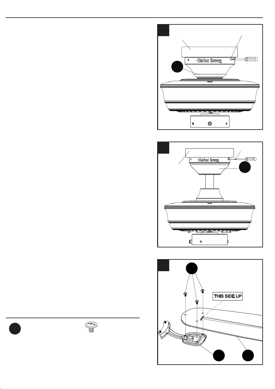
2. Re-install the two screws that were previously
removed (step 3, page 6) to fully secure the
canopy (B) to the mounting bracket (A).
3. Directly align the locking slots of the canopy
(B) with the two screws previously loosened
(step 3, page 6) in the mounting bracket
(A). Push up to engage the slots and turn
clockwise to lock in place. Immediately tighten
the two screws rmly, then re-install the two
screws that were previously removed (step 3,
page 6) to fully secure the canopy (B) to the
mounting bracket (A).
4. Attach blade (G) to a blade bracket (F)
using three blade screws (DD).
Repeat for remaining blade assemblies.
Screw
Outlet box
B
2
B
Screw
Outlet box
3
DD
F
G
4
Hardware Used
Blade Screw x 16
DD
1. Connect the BLACK and BLUE wires from
the fan to the house BLACK wire. Connect
the WHITE wire from fan to the house WHITE
wire. Connect all GROUNDED (GREEN)
wires together from fan to the house GREEN/
GROUND wire.
NOTE: BLACK wire is hot power for fan.
BLUE wire is hot power for light kit. WHITE
wire is common for fan and light kit. GREEN
wire is ground wire. If house wires are
different colors than referred to above, stop
immediately. Consult a licensed electrician to
determine proper wiring.
Hardware Used
Wire Connector x 4
AA
If you installed the fan with “Closemount Style
Fan Mounting”, continue to Steps 1 and 2. If
you installed the fan with “Downrod Style Fan
Mounting”, skip to Step 3.
Ground/Green
Black
White
Ground/
Green
Black
Blue
White
Supply circuit
Speed
switch
Outlet
box
blue
black
white
green
white
GREEN/
GROUND
black
1
You may now proceed to Step 4.
1110
WIRING
2. To connect wires, twist wire ends together
and screw wire with wire connectors (AA) in a
clockwise direction. Tape the wire connectors
(AA) and wires together with electrical tape (not
included). Be sure no bare wire or wire strands
are visible after making connection.
1. Remove the fan from the hook on the
mounting bracket (A). Align the locking
slots of the canopy (B) with the two screws
previously loosened (step 3, page 6) in the
mounting bracket (A). Push up to engage
the slots and turn clockwise to lock in place.
Immediately tighten the two screws rmly.
AA
2
Outlet
box
Screws
Hook
Locking
slot
s
B
A
1
Place GREEN and WHITE connections on
opposite side of box from the BLACK and
BLUE connections. The splices should be
turned upward and pushed carefully up into
the outlet box.
FINAL INSTALLATION
FINAL INSTALLATION
2. Re-install the two screws that were previously
removed (step 3, page 6) to fully secure the
canopy (B) to the mounting bracket (A).
3. Directly align the locking slots of the canopy
(B) with the two screws previously loosened
(step 3, page 6) in the mounting bracket
(A). Push up to engage the slots and turn
clockwise to lock in place. Immediately tighten
the two screws rmly, then re-install the two
screws that were previously removed (step 3,
page 6) to fully secure the canopy (B) to the
mounting bracket (A).
4. Attach blade (G) to a blade bracket (F)
using three blade screws (DD).
Repeat for remaining blade assemblies.
Screw
Outlet box
B
2
B
Screw
Outlet box
3
DD
F
G
4
Hardware Used
Blade Screw x 16
DD
1. Connect the BLACK and BLUE wires from
the fan to the house BLACK wire. Connect
the WHITE wire from fan to the house WHITE
wire. Connect all GROUNDED (GREEN)
wires together from fan to the house GREEN/
GROUND wire.
NOTE: BLACK wire is hot power for fan.
BLUE wire is hot power for light kit. WHITE
wire is common for fan and light kit. GREEN
wire is ground wire. If house wires are
different colors than referred to above, stop
immediately. Consult a licensed electrician to
determine proper wiring.
Hardware Used
Wire Connector x 4
AA
If you installed the fan with “Closemount Style
Fan Mounting”, continue to Steps 1 and 2. If
you installed the fan with “Downrod Style Fan
Mounting”, skip to Step 3.
Ground/Green
Black
White
Ground/
Green
Black
Blue
White
Supply circuit
Speed
switch
Outlet
box
blue
black
white
green
white
GREEN/
GROUND
black
1
You may now proceed to Step 4.
1312
FINAL INSTALLATION
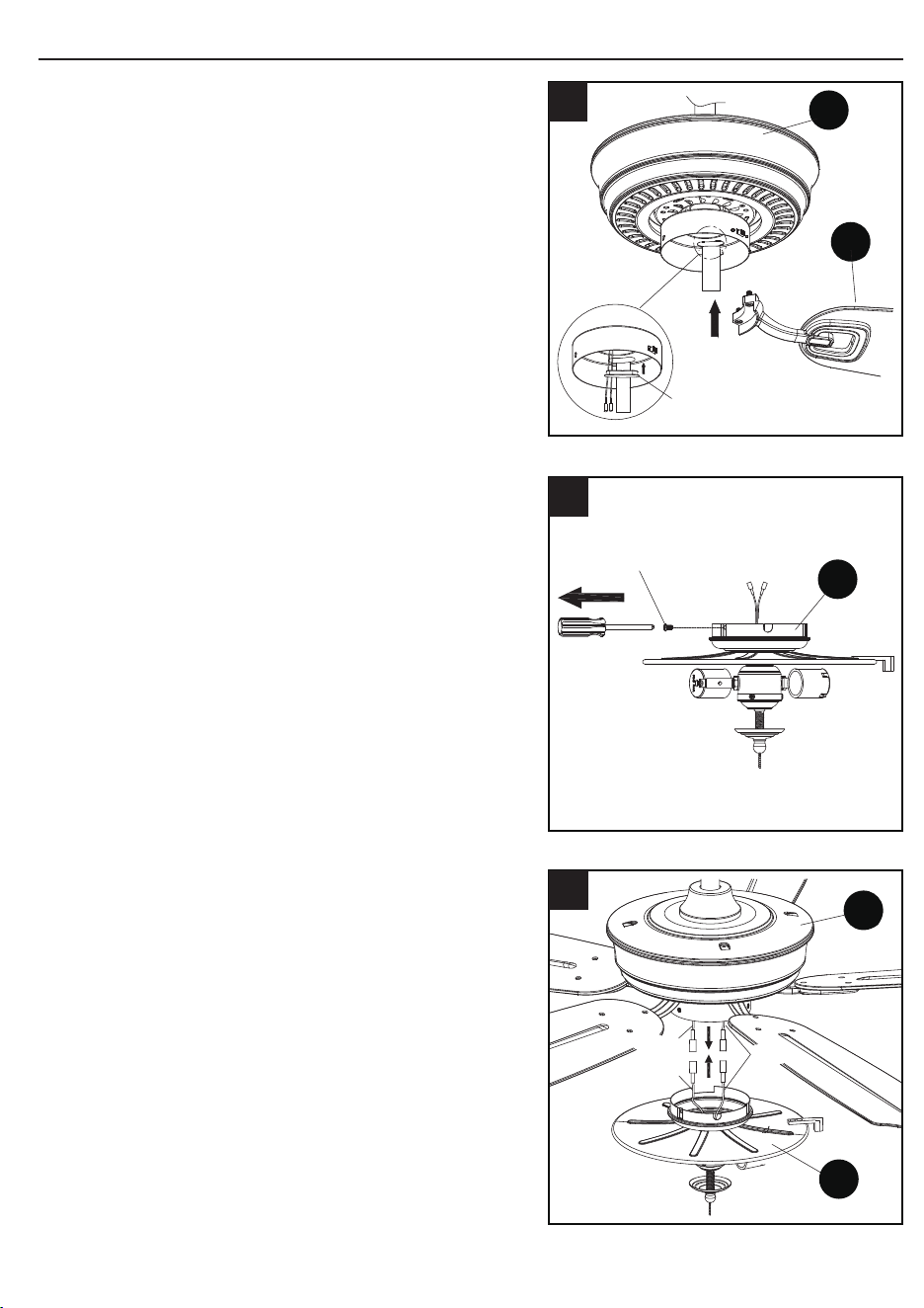
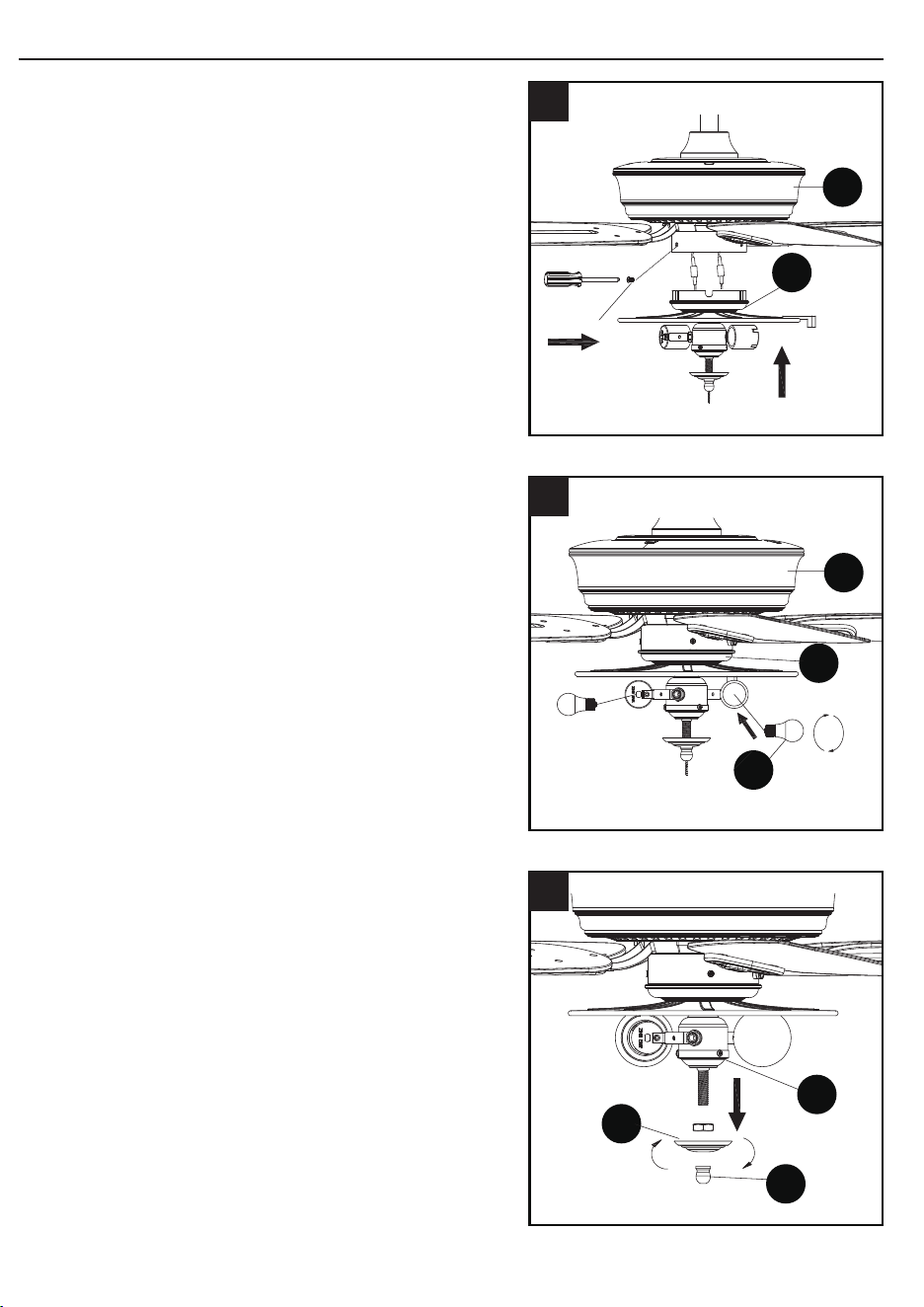
6. To install the fan WITH the light, remove and
save the three preassembled screws from the
switch cup cover of light kit (I).
7. Connect the adapter plug of the BLUE wire
from the fan motor assembly (H) to the
adapter plug of the BLACK wire from the light
kit (I) and connect the adapter plug of the
WHITE wire from the fan motor assembly (H)
to the adapter plug of the WHITE wire from
the light kit (I).
Screw
I
6
H
White
Black
Blue
I
7
FINAL INSTALLATION
8. Attach light kit (I) to the bottom of the motor
housing (H) by aligning the holes in each
part and re-installing the previously removed
screws (Step 6, page 12). Tighten securely.
9. Install bulbs (K) into sockets in light kit (I).
10. Remove the preassembled nial (M), bowl
cap (L) and the hex nut from the light kit (I).
I
Screw
H
8
H
K
I
9
I
M
L
10
5. Fasten the blade bracket (F) to the motor by
inserting the alignment post into the slot on the
bottom of the motor housing (H) and tightening
the blade bracket screws with washers. Please
note that the blade bracket screws with washers
are pre-installed into the blade bracket (F).
NOTE: The switch cup has an access hole that
is sealed with a waterproof rubber plug. Remove
the rubber plug to allow the screwdriver to reach
the screws in the blade bracket. Position the blade
bracket on the motor and tighten by inserting the
screwdriver through the access hole. Once all
blade brackets have been attached, replace the
rubber plug in the access hole.
F
H
Waterproof
rubber plug
5
Repeat this step for the remaining blade
assemblies.
NOTE: To install this fan WITH the light
kit, continue to step 6. To install the fan
WITHOUT the light kit, proceed to step 13.
1312
FINAL INSTALLATION
6. To install the fan WITH the light, remove and
save the three preassembled screws from the
switch cup cover of light kit (I).
7. Connect the adapter plug of the BLUE wire
from the fan motor assembly (H) to the
adapter plug of the BLACK wire from the light
kit (I) and connect the adapter plug of the
WHITE wire from the fan motor assembly (H)
to the adapter plug of the WHITE wire from
the light kit (I).
Screw
I
6
H
White
Black
Blue
I
7
FINAL INSTALLATION
8. Attach light kit (I) to the bottom of the motor
housing (H) by aligning the holes in each
part and re-installing the previously removed
screws (Step 6, page 12). Tighten securely.
9. Install bulbs (K) into sockets in light kit (I).
10. Remove the preassembled nial (M), bowl
cap (L) and the hex nut from the light kit (I).
I
Screw
H
8
H
K
I
9
I
M
L
10
5. Fasten the blade bracket (F) to the motor by
inserting the alignment post into the slot on the
bottom of the motor housing (H) and tightening
the blade bracket screws with washers. Please
note that the blade bracket screws with washers
are pre-installed into the blade bracket (F).
NOTE: The switch cup has an access hole that
is sealed with a waterproof rubber plug. Remove
the rubber plug to allow the screwdriver to reach
the screws in the blade bracket. Position the blade
bracket on the motor and tighten by inserting the
screwdriver through the access hole. Once all
blade brackets have been attached, replace the
rubber plug in the access hole.
F
H
Waterproof
rubber plug
5
Repeat this step for the remaining blade
assemblies.
NOTE: To install this fan WITH the light
kit, continue to step 6. To install the fan
WITHOUT the light kit, proceed to step 13.
FINAL INSTALLATION
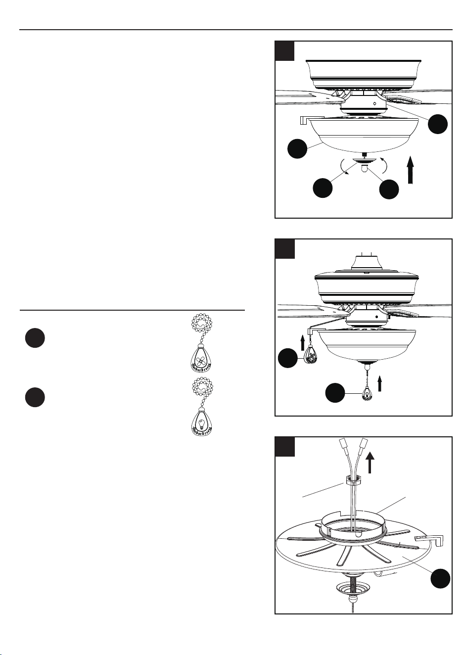
12. Attach fan pull chain extension (BB) and light
pull chain extension (CC).
Assembly is now complete
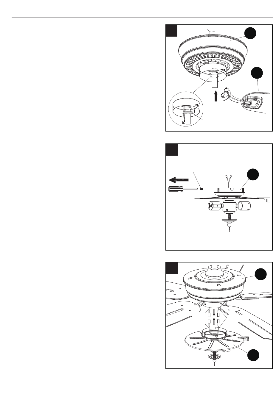
13. To install the fan WITHOUT the light,
remove the hex nut preassembled inside the
switch housing cover of the light kit (I) and
detach the switch housing cover.
BB
CC
12
I
Hex Nut
Switch
housing
cover
13
FINAL INSTALLATION
14. Place the plug (FF) into the center hole of the
switch housing cover.
15. R
emove and save the three preassembled
screws from the switch housing cover.
Attach switch housing cover to the bottom of
the motor housing (H) by aligning the holes
in each part and re-installing the previously
removed screws. Tighten securely.
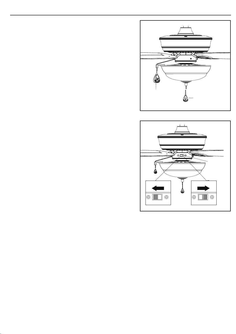
16. A
ttach fan pull chain extension (BB).
I
FF
Switch
housing
cover
14
I
Screw
H
15
BB
H
Fan pull chain
16
11. Place glass (J) on the preassembled
pipe on light kit (I) until it is ush with the
preassembled metal disk. Secure with
previously removed hex nut, bowl cap (L) and
nial (M). Tighten securely.
I
J
L
M
11
Hardware Used
Fan pull chain extensions
x 1
BB
Light pull chain extensions
x 1
CC
1514
FINAL INSTALLATION
12. Attach fan pull chain extension (BB) and light
pull chain extension (CC).
Assembly is now complete
13. To install the fan WITHOUT the light,
remove the hex nut preassembled inside the
switch housing cover of the light kit (I) and
detach the switch housing cover.
BB
CC
12
I
Hex Nut
Switch
housing
cover
13
FINAL INSTALLATION
14. Place the plug (FF) into the center hole of the
switch housing cover.
15. R
emove and save the three preassembled
screws from the switch housing cover.
Attach switch housing cover to the bottom of
the motor housing (H) by aligning the holes
in each part and re-installing the previously
removed screws. Tighten securely.
16. A
ttach fan pull chain extension (BB).
I
FF
Switch
housing
cover
14
I
Screw
H
15
BB
H
Fan pull chain
16
11. Place glass (J) on the preassembled
pipe on light kit (I) until it is ush with the
preassembled metal disk. Secure with
previously removed hex nut, bowl cap (L) and
nial (M). Tighten securely.
I
J
L
M
11
Hardware Used
Fan pull chain extensions
x 1
BB
Light pull chain extensions
x 1
CC
1514
OPERATING INSTRUCTIONS
1716
TROUBLESHOOTING
CARE AND MAINTENANCE
• Important: Shut off main power supply before beginning any maintenance.
• Do not use water or detergents when cleaning the fan or fan blades. A dry dust cloth or
lightly dampened cloth will be suitable for most cleaning.
• Clean fan housing with only a soft brush or lint-free cloth to avoid scratching the nish.
Clean blades with a lint-free cloth. You may occasionally apply a light coat of furniture
polish to blades for added protection.
• At least twice a year, tighten all screws and lower canopy to check mounting bracket
screws and downrod assembly.
• Bulb replacement: Use 60-watt max. medium base incandescent bulbs or LED
equivalent.
PROBLEM POSSIBLE CAUSE CORRECTIVE ACTION
Fan does not move. 1. Chain switch is “off”.
2. Faulty wire
connection.
3. Reverse switch not
engaged.
1. Pull chain switch.
2. Turn power off. Loosen
canopy, check all connections.
3. Push switch rmly either way.
Noisy operation. 1. Blades are loose.
2. Cracked blade.
3. Unapproved speed
control.
1. Tighten all blade screws.
2. Replace blades (call customer
service).
3. Replace with an approved
speed control device.
Excessive wobbling. 1. The blades are loose.
2. Blade brackets
incorrectly attached.
3. The fan is not
securely mounted.
4. Fan too close to
vaulted ceiling.
1. Tighten all blade screws.
2. Reinstall blade brackets.
3. Turn power off. Carefully
loosen the canopy and
remount securely.
4. Lower fan or move it to
another location.
1. PULL CHAIN:
2. REVERSE SWITCH:
When the season changes, you may want to
change the direction your fan spins. To switch
between clockwise and counterclockwise
rotations, ip the fan reversal switch.
WARNING: Wait for fan to stop before
reversing the switch.
A. In cooler weather, clockwise rotation
creates an upward airow, which moves
hot air from the ceiling into the room.
Push the switch RIGHT.
B. In warmer weather, counterclockwise
rotation creates a downward airow,
which cools the air. Push the switch
LEFT.
• The fan pull chain is for motor speed
control: High, Medium, Low and Off.
Pull chain once for each position.
• The light pull chain controls the light
xture either ON or OFF with each pull
of the chain.
Fan pull
chain
Light pull
chain
Reverse
switch
WARRANTY
REPLACEMENT PARTS LIST
Printed in China
For replacement parts, call our customer service department at 1-800-643-0067,
8 a.m. - 6 p.m., EST, Monday - Thursday, 8 a.m. - 5 p.m., EST, Friday.
18
The manufacturer warrants this fan to be free from defects in workmanship and material present at
time of shipment from the factory for lifetime limited from the date of purchase. This warranty applies
only to the original purchaser. The manufacturer agrees to correct such defect at no charge or at our
option replace the ceiling fan with a comparable or superior model.
To obtain warranty service, present a copy of your sales receipt as proof of purchase. All cost of
removal and reinstallation are the expressed responsibility of the purchaser. Any damage to the
ceiling fan by accident, misuse, or improper installation, or by afxing accessories not produced by
the manufacturer of the fan, are at the purchaser’s own responsibility. The manufacturer assumes
no responsibility whatsoever for fan installation during the lifetime limited warranty. Any service
performed by an unauthorized person will render the warranty invalid.
Due to varying climatic conditions, this warranty does not cover changes in brass nish, rusting,
pitting, tarnishing, corroding, or peeling. Brass nish fans maintain their beauty when protected from
varying weather conditions. Any glass provided with this fan is not covered by this warranty. Any
replacement of defective parts for the ceiling fan must be reported within the rst year from the date
of purchase. For the balance of the warranty, call our customer service department at 1-800-643-
0067 for return authorization and shipping instructions so that we may repair or replace the ceiling
fan. Any fan or parts returned improperly packaged is the sole responsibility of the purchaser. There
is no further expressed warranty. The manufacturer disclaims any and all implied warranties.
The duration of any implied warranty which can not be disclaimed is limited to the lifetime limited
period as specied in our warranty. The manufacturer shall not be liable for incidental, consequential
or special damages arising at or in connection with product use or performance except as may
otherwise be accorded by law. This warranty gives you specic legal rights an you also have other
rights which may vary from state to state. This warranty supersedes all prior warranties.
Note: A small amount of “wobble” is normal and should not be considered a defect.
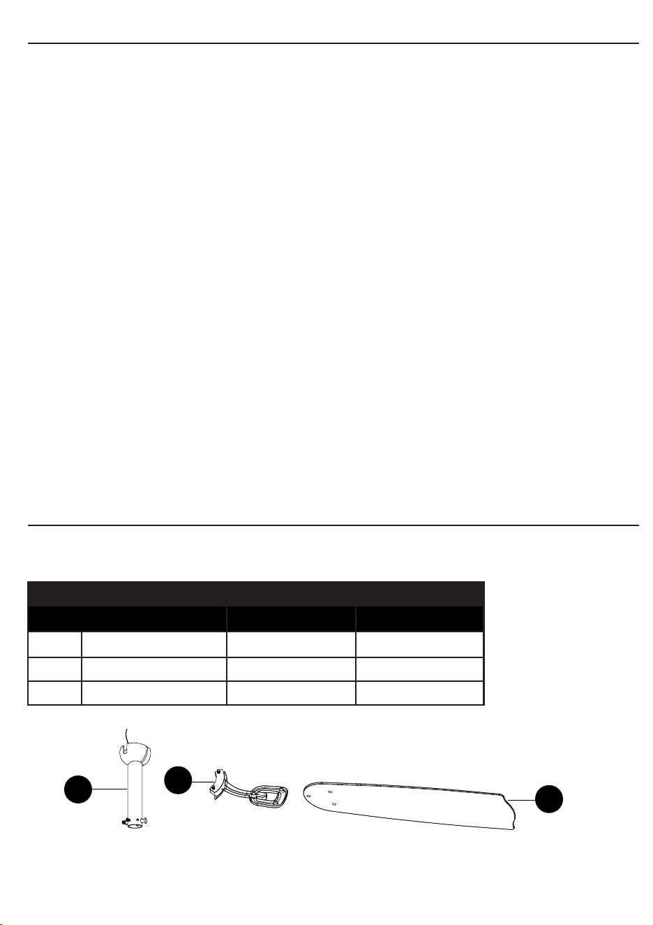
PART DESCRIPTION PART #
Item #0747603 Item #0747604
E Downrod Assembly 102200-0289LO 102200-0289ZW
F Blade Bracket 104000-0410LO 104000-0410ZW
G Blade 108100-005079 108100-0049ZW
F
G
E
VENTILADOR DE TECHO
ECHOLAKE
ARTÍCULO #0747603, 0747604
MODELO #00894, 00893
Número de serie Fecha de compra
Harbor Breeze
®
es una marca registrada
de LF, LLC. Todos los derechos reservados.t
¿Preguntas, problemas, piezas faltantes? Antes de volver a la tienda, llame a
nuestro Departamento de Servicio al Cliente al 1-800-643-0067, de lunes a jueves,
de 8 a.m. a 6 p.m., y los viernes de 8 a.m. a 5 p.m., hora estándar del Este.
ADJUNTE SU RECIBO AQUÍ
MODELO UL #52-GV
19

ÍNDICE
CONTENIDO DEL PAQUETE
PIEZA DESCRIPCIÓN CANTIDAD
A Soporte de montaje (preensamblada en la base [B]) 1
B Base 1
C Cubierta de la base (preensamblada en la base [B]) 1
D Cubierta de la horquilla 1
E Ensamble de la varilla 1
F Abrazadera del aspa 5
G Aspa 5
H Carcasa del motor 1
I Kit de iluminación 1
J Pantalla de vidrio 1
K Bombilla 2
L Tapa de la pantalla (preensamblada en el kit de iluminación [I]) 1
M Remate (preensamblado en el kit de iluminación [I]) 1
K
F
A
I
H
G
D
C
B
E
J
L
M
M
2120
Contenido del paquete............................................................................................. 21
Aditamentos.............................................................................................................. 22
Preparación.............................................................................................................. 22
Información de segurida...........................................................................................23
Instrucciones de ensamblaje o instalación................................................................ 24
Instrucciones de funcionamiento............................................................................. 34
Cuidado y mantenimiento ...................................................................................... 35
Solución de problemas............................................................................................. 35
Garantía.................................................................................................................... 36
Lista de piezas de repuesto..................................................................................... 36
ADITAMENTOS
INFORMACIÓN DE SEGURIDAD
LEA Y GUARDE ESTAS INSTRUCCIONES
Lea y comprenda completamente este manual antes de intentar ensamblar, usar o instalar
el producto.
• Cuando use una caja de salida existente, asegúrese de que la caja esté sujeta de
forma segura a la estructura del edicio y que pueda soportar el peso completo del
ventilador para evitar potenciales lesiones graves o la muerte.
• Todo el cableado debe cumplir el Código Eléctrico Nacional “ANSI/NFPA 70” y los
códigos eléctricos locales. La instalación eléctrica debe ser realizada por un electricista
calicado y autorizado.
• NO utilice bombillas de un vataje superior al valor máximo establecido en el
ensamble y en este manual. La utilización de una bombilla cuyo vataje sea superior al
especicado incrementará la temperatura del ensamble y causará riesgo de incendio.
• Desconecte el circuito de suministro de electricidad del ventilador antes de instalar
el kit.
• Los diagramas eléctricos tienen una nalidad de referencia únicamente.
• El peso neto de este ventilador, incluido el kit de iluminación, es: 9,75 kg.
ADVERTENCIA
• RIESGO DE LESIONES PERSONALES, INCENDIO O DESCARGA ELÉCTRICA:
Para reducir el riesgo de incendio, descargas eléctricas o lesiones personales,
monte el ventilador en una caja de salida marcada como “ACCEPTABLE FOR FAN
SUPPORT OF 35.1 LBS OR LESS” (Apta para sostener ventiladores de 15,92 kg o
menos) y utilice los tornillos de montaje que se proporcionan con la caja de salida. La
mayoría de las cajas de salida que se usan comúnmente para sostener lámparas no
son aptas para sostener un ventilador y puede ser necesario reemplazarlas. Si tiene
dudas, consulte con un electricista calicado y autorizado.
PRECAUCIÓN
• RIESGO DE LESIONES PERSONALES: Para reducir el riesgo de lesiones personales,
no doble las abrazaderas de las aspas al instalarlas, equilibrar las aspas o limpiar el
ventilador. NO coloque objetos extraños entre las aspas en movimiento del ventilador.
2322
PREPARACIÓN
Antes de comenzar a ensamblar el producto, asegúrese de tener todas las piezas. Compare
las piezas con la lista del contenido del paquete y la lista del contenido de aditamentos. No
intente ensamblar el producto si falta alguna pieza o si estas están dañadas.
Tiempo estimado de ensamblaje: 45 minutos.
Herramientas necesarias para el ensamblaje (no se incluyen): Destornillador Phillips,
escalera de tijera, cinta aislante, pinzas, pinzas cortacables, pinzas pelacables.
Herramientas útiles (no se incluyen): Probador de circuito eléctrico.
AA
BB
CC
DD
EE
FF
Extension para
la cadena de tiro
del ventilador
Cant. 1
(NO ESTÁ A ESCALA)
Extension para
la cadena de tiro
del kit de iluminación
Cant. 1
(NO ESTÁ
A ESCALA)
Conector
de cables
Cant. 4
Tornillo del aspa
Cant. 16
Tapón
Cant. 1
Empaquetadura
de goma
Cant. 1
(NO ESTÁ A ESCALA)
INSTRUCCIONES DE ENSAMBLAJE
1. Determine el método de instalación que
utilizará.
a. Montaje de varilla (techos normales o en
ángulo)
b. Montaje cerrado (solo para techos
normales)
IMPORTANTE: Si realiza el montaje en ángulo,
verique que el ángulo del techo no tenga una
inclinación superior a los 20°.
2. Retire y deseche los cinco accesorios de goma
y los cinco tornillos de montaje de la parte
inferior del ensamble de la carcasa del motor
(H).
NOTA: El soporte del interruptor cuenta con un
oricio de acceso sellado con un tapón impermeable
de goma. Retire el tapón de goma para que pueda
desatornillar los tornillos de la abrazadera del
aspa. Coloque la abrazadera del aspa en el motor
y apriete con el destornillador a través del oricio
de acceso. Una vez que se aseguraron todas las
abrazaderas del aspa, vuelva a colocar el tapón de
goma en el oricio de acceso.
3. Retire el soporte de montaje (A) de la
base (B) aojando los cuatro tornillos de
la parte superior de la base (B). Retire los
dos tornillos sin ranura y guárdelos.
2524
4. Instale el soporte de montaje (A) en la caja
de salida (no se incluye) con los dos tornillos
que se incluyen con la caja de salida. Apriete
rmemente los dos tornillos.
A
B
1
Caja de
salida
A
4
Sujetador
Pasador
E
1
C
B
D
E
2
Accesorio de
goma y tornillo
H
Tapón
impermeable
de goma
2
A
B
Retire y
guarde
Afloje, pero
no retire
3
INSTRUCCIONES DE ENSAMBLAJE
ESTILO DE MONTAJE DE VARILLA DEL VENTILADOR
1. Retire el pasador y el sujetador del ensamble
de la varilla (E) y guárdelos.
2. Inserte el ensamble de la varilla (E) por
la base (B), la cubierta de la base (C) y la
cubierta de la horquilla (D). Pase los cables
desde el ensamble de carcasa del motor (H)
a través del ensamble de la varilla (E).
Siga las instrucciones de instalación para el
Estilo de montaje de varilla del ventilador
en la página 25 o para el Estilo de montaje
cerrado del ventilador en la página 26,
dependiendo del método de instalación (A o B)
que escoja en el paso 1 en la página 24.
INSTRUCCIONES DE ENSAMBLAJE
1. Determine el método de instalación que
utilizará.
a. Montaje de varilla (techos normales o en
ángulo)
b. Montaje cerrado (solo para techos
normales)
IMPORTANTE: Si realiza el montaje en ángulo,
verique que el ángulo del techo no tenga una
inclinación superior a los 20°.
2. Retire y deseche los cinco accesorios de goma
y los cinco tornillos de montaje de la parte
inferior del ensamble de la carcasa del motor
(H).
NOTA: El soporte del interruptor cuenta con un
oricio de acceso sellado con un tapón impermeable
de goma. Retire el tapón de goma para que pueda
desatornillar los tornillos de la abrazadera del
aspa. Coloque la abrazadera del aspa en el motor
y apriete con el destornillador a través del oricio
de acceso. Una vez que se aseguraron todas las
abrazaderas del aspa, vuelva a colocar el tapón de
goma en el oricio de acceso.
3. Retire el soporte de montaje (A) de la
base (B) aojando los cuatro tornillos de
la parte superior de la base (B). Retire los
dos tornillos sin ranura y guárdelos.
2524
4. Instale el soporte de montaje (A) en la caja
de salida (no se incluye) con los dos tornillos
que se incluyen con la caja de salida. Apriete
rmemente los dos tornillos.
A
B
1
Caja de
salida
A
4
Sujetador
Pasador
E
1
C
B
D
E
2
Accesorio de
goma y tornillo
H
Tapón
impermeable
de goma
2
A
B
Retire y
guarde
Afloje, pero
no retire
3
INSTRUCCIONES DE ENSAMBLAJE
ESTILO DE MONTAJE DE VARILLA DEL VENTILADOR
1. Retire el pasador y el sujetador del ensamble
de la varilla (E) y guárdelos.
2. Inserte el ensamble de la varilla (E) por
la base (B), la cubierta de la base (C) y la
cubierta de la horquilla (D). Pase los cables
desde el ensamble de carcasa del motor (H)
a través del ensamble de la varilla (E).
Siga las instrucciones de instalación para el
Estilo de montaje de varilla del ventilador
en la página 25 o para el Estilo de montaje
cerrado del ventilador en la página 26,
dependiendo del método de instalación (A o B)
que escoja en el paso 1 en la página 24.

2726
ESTILO DE MONTAJE DE VARILLA DEL VENTILADOR
3. Aoje los dos tornillos de jación de la horquilla.
Deslice el ensamble de la varilla (E) en la
horquilla, alineando los oricios del ensamble
de la varilla (E) y la horquilla. Inserte el pasador
por la horquilla y el ensamble de la varilla
(E), luego inserte el sujetador que retiró con
anterioridad en el pasador hasta que encaje en
su lugar. Apriete los tornillos de jación. Deslice
la cubierta de la horquilla (D) hacia abajo hasta
que encaje en la carcasa del motor (H).
4. Instale la bola para colgar en la parte superior
del ensamble de la varilla (E) en la abertura del
soporte de montaje (A). Gire el ventilador hasta
que la ranura de la bola para colgar calce con la
lengüeta del soporte de montaje (A).
1. Retire cubierta de la base (C) de la parte
inferior de la base (B).
Sujetador
Pasador
Tornillo
de fijación
Horquilla
E
D
H
3
Ranura
Lengüeta
A
E
4
B
C
1
PELIGRO: Tenga cuidado cuando alinee la
lengüeta con la ranura. Si no calza bien, es posible
que el ventilador se caiga, lo que podría provocar
lesiones graves o la muerte.
ESTILO DE MONTAJE CERRADO DEL VENTILADOR
ESTILO DE MONTAJE CERRADO DEL VENTILADOR
2. Retire tres de los seis tornillos y arandelas de
seguridad (uno del otro) asegurando el collar
del motor a la parte superior de la carcasa del
motor del ventilador y guárdelo.
3. Coloque la empaquetadura de goma (EE)
sobre los tornillos restantes en la carcasa
del motor (H). Pase los cables por el oricio
de la base (B) y je la base (B) a la carcasa
del motor (H) con los tres tornillos retirados
previamente en el paso anterior. Apriete
rmemente los tornillos.
4. Cuelgue temporalmente la carcasa del
motor (B) en el gancho del soporte de
montaje (A) con uno de los oricios
sin ranura de la base (B). Esto permite
tener las manos libres para conectar el
cableado.
H
2
H
B
EE
3
B
A
Gancho
4
Continúe con las INSTRUCCIONES DE
CABLEADO en la página 28.
Aditamentos utilizados
Empaquetadura
de goma
x 1
EE
2928
CABLEADO
2. Para conectar los cables, tuerza sus extremos y
atorníllelos con los conectores de cables (AA) en
dirección de las manecillas del reloj. Encinte los
conectores de cables (AA) y los cables con cinta
aislante (no se incluye). Asegúrese de que no haya
cables desnudos ni visibles después de hacer la
conexión.
1. Retire el ventilador del gancho del soporte de
montaje (A). Alinee las ranuras de empalme
de la base (B) con los dos tornillos que aojó
previamente (paso 3, pág. 6) en el soporte de
montaje (A). Presione para enganchar las ranuras
y gírelas en dirección de las manecillas del reloj
para jar en su lugar. Apriete rmemente los dos
tornillos de inmediato.
AA
2
Caja de salida
Tornillos
Gancho
Conector
de cables
B
A
1
Coloque las conexiones VERDES y BLANCAS en el
lado opuesto de la caja donde se ubican las conexiones
NEGRAS y AZULES. Se deben girar los empalmes
hacia arriba y empujar con cuidado hasta introducirlos
en la caja de salida.
INSTALACIÓN FINAL
INSTALACIÓN FINAL
2. Vuelva a instalar los dos tornillos que retiró
previamente (paso 3, pág. 24) para asegurar
la base (B) al soporte de montaje (A).
3. Alinee directamente las ranuras de empalme
de la base (B) con los dos tornillos que aojó
previamente (paso 3, pág. 24) en el soporte
de montaje (A). Presione para enganchar las
ranuras y gírelas en dirección de las manecillas
del reloj para jar en su lugar. Luego, apriete
los dos tornillos con rmeza y vuelva a instalar
los dos tornillos que retiró previamente (paso 3,
pág. 24) para asegurar la base (B) al soporte
de montaje (A).
4. Fije un aspa (G) a una abrazadera del aspa (F)
con tres tornillos del aspa (DD).
Repita para los ensambles de las aspas
restantes.
Tornillo
Caja de salida
B
2
B
Tornillo
Caja
de salida
3
DD
F
G
4
Aditamentos utilizados
Tornillo del aspa x 16
DD
1. Conecte los conductores NEGROS y AZULES del
ventilador al conductor NEGRO de la caja. Conecte
el conductor BLANCO del ventilador al conductor
BLANCO de la caja. Conecte todos los conductores
CON PUESTA A TIERRA (VERDES) juntos del
ventilador con el conductor VERDE/PUESTA A
TIERRA de la caja.
NOTA: El conductor NEGRO es el que proporciona
alimentación al ventilador. El conductor AZUL es el
conductor con alimentación del kit de iluminación. El
conductor BLANCO es el conductor común para el
ventilador y el kit de iluminación. El conductor VERDE
es de puesta a tierra. Si los conductores interiores son
de color diferente a los mencionados anteriormente,
deténgase de inmediato. Consulte con un electricista
certicado para que determine el cableado correcto.
Aditamentos Utilizados
Conector de cables
x 4
AA
Si instaló el ventilador con el “Estilo de montaje
cerrado del ventilador”, continúe con los pasos 1 y
2. Si instaló el ventilador con el “Estilo de montaje de
varilla del ventilador”, continúe con el paso 3.
Puesta a tierra/Verde
Negro
Blanco
Puesta a
tierra/
Verde
Negro
Azul
Blanco
Circuito de suministro
Regulador de
velocidada
Caja de
salida
Azul
Negro
Blanco
Verde
Blanco
VERDE/
PUESTA
A TIERRA
Negro
1
Continúe con el paso 4.
3130
INSTALACIÓN FINAL
6. Para instalar el ventilador CON el kit, retire
y guarde los tres tornillos preensamblados
del interruptor del kit de iluminación (I).
7. Conecte el enchufe del adaptador del
conductor AZUL del ensamble del motor
del ventilador (H) al enchufe del adaptador
del conductor NEGRO del kit de iluminación
(I) y conecte el enchufe del adaptador del
conductor BLANCO del ensamble del motor
del ventilador (H) al enchufe del adaptador del
conductor BLANCO del kit de iluminación (I).
Tornillo
I
6
H
Negro
Azul
I
Blanco
7
INSTALACIÓN FINAL
8. Fije el kit de iluminación (I) en la parte inferior
de la carcasa del motor (H) y alinee los oricios
en cada parte y vuelva a colocar los tornillos
que retiró previamente (paso 6, pág. 30).
Apriete rmemente.
9. I
nstale las bombillas (K) en los portalámparas
del kit de iluminación (I).
10. R
etire el remate (M), la tapa de la pantalla (L),
y la tuerca hexagonal del kit de iluminación (I).
I
Tornillo
H
8
H
K
I
9
I
M
L
10
5. Fije la abrazadera del aspa (F) al motor
insertando el poste de alineación en la ranura
de la parte inferior de la carcasa del motor (H)
y ajuste los tornillos de las abrazaderas de
aspa con las arandelas. Tenga en cuenta que
los tornillos de las abrazaderas de aspa con
arandelas están preinstalados en la abrazadera
del aspa. Repita el paso para las abrazaderas
de aspa restantes (F).
NOTA: El soporte del interruptor cuenta con
un oricio de acceso sellado con un tapón
impermeable de goma. Retire el tapón de goma
para que pueda desatornillar los tornillos de la
abrazadera del aspa. Coloque la abrazadera del
aspa en el motor y apriete con el destornillador
a través del oricio de acceso. Una vez que se
aseguraron todas las abrazaderas del aspa,
vuelva a colocar el tapón de goma en el oricio
de acceso.
F
H
Tapón impermeable
de goma
5
Repita este paso para el ensamblaje de las aspas
restantes.
NOTA: Para instalar el ventilador CON el kit de
iluminación, continúe con el paso 6. Para instalar
el ventilador SIN el kit de iluminación, continúe
con el paso 13.
INSTALACIÓN FINAL
12. Fije la extensión de la cadena de tiro del
ventilador (BB) y la extensión de la cadena
de tiro del kit de iluminación (CC).
El ensamblaje está terminado.
13. Para instalar el ventilador SIN el kit, retire
la tuerca hexagonal preensambladas dentro
de la cubierta de la carcasa del interruptor
del kit de iluminación (I) y retire la cubierta
de la carcasa del interruptor.
BB
CC
12
I
Tuerca
hexagonal
Cubierta de
la carcasa
del
interruptor
13
INSTALACIÓN FINAL
14. Reemplace el tapón (FF) del oricio central
de la cubierta de la carcasa del interruptor.
15. R
etire y guarde los tres tornillos
preensamblados de la cubierta de la
carcasa del interruptor. Fije la cubierta de la
carcasa del interruptor en la parte inferior de
la carcasa del motor (H) y alinee los oricios
en cada parte y vuelva a colocar los tornillos
que retiró previamente. Apriete rmemente.
16. F
ije la extensión para la cadena de tiro
del ventilador (BB).
I
FF
Cubierta de
la carcasa
del
interruptor
14
I
Tornillo
H
15
BB
H
Cadena de tiro
del ventilador
16
11. Coloque el vidrio (J) en el tubo preensamblado
del kit de iluminación (I) hasta que quede al
ras con el disco de metal preensamblado. Fije
con la tuerca hexagonal, la tapa de la pantalla
(L), y el remate (M) que retiró previamente.
Apriete rmemente.
I
J
L
M
11
Aditamentos utilizados
Extensiones para la cadena
de tiro del ventilador
x 1
BB
Extensiones para la
cadena de tiro del kit de
iluminación
x 1
CC
3332
INSTALACIÓN FINAL
12. Fije la extensión de la cadena de tiro del
ventilador (BB) y la extensión de la cadena
de tiro del kit de iluminación (CC).
El ensamblaje está terminado.
13. Para instalar el ventilador SIN el kit, retire
la tuerca hexagonal preensambladas dentro
de la cubierta de la carcasa del interruptor
del kit de iluminación (I) y retire la cubierta
de la carcasa del interruptor.
BB
CC
12
I
Tuerca
hexagonal
Cubierta de
la carcasa
del
interruptor
13
INSTALACIÓN FINAL
14. Reemplace el tapón (FF) del oricio central
de la cubierta de la carcasa del interruptor.
15. R
etire y guarde los tres tornillos
preensamblados de la cubierta de la
carcasa del interruptor. Fije la cubierta de la
carcasa del interruptor en la parte inferior de
la carcasa del motor (H) y alinee los oricios
en cada parte y vuelva a colocar los tornillos
que retiró previamente. Apriete rmemente.
16. F
ije la extensión para la cadena de tiro
del ventilador (BB).
I
FF
Cubierta de
la carcasa
del
interruptor
14
I
Tornillo
H
15
BB
H
Cadena de tiro
del ventilador
16
11. Coloque el vidrio (J) en el tubo preensamblado
del kit de iluminación (I) hasta que quede al
ras con el disco de metal preensamblado. Fije
con la tuerca hexagonal, la tapa de la pantalla
(L), y el remate (M) que retiró previamente.
Apriete rmemente.
I
J
L
M
11
Aditamentos utilizados
Extensiones para la cadena
de tiro del ventilador
x 1
BB
Extensiones para la
cadena de tiro del kit de
iluminación
x 1
CC
3332

INSTRUCCIONES DE FUNCIONAMIENTO
3534
SOLUCIÓN DE PROBLEMAS
CUIDADO Y MANTENIMIENTO
• Importante: Antes de realizar cualquier trabajo de mantenimiento, desconecte el
suministro de electricidad principal.
• No utilice agua ni detergentes para limpiar el ventilador o las aspas. Se recomienda
utilizar un paño suave y seco o un paño levemente humedecido para limpiar el
producto.
• Limpie la carcasa del ventilador solo con un cepillo suave o con un paño sin pelusas
para evitar que se raye el acabado. Limpie las aspas con un paño sin pelusas. De
vez en cuando, puede aplicar una na capa de pulidor para muebles en las aspas
para darles más protección.
• Al menos dos veces al año, apriete todos los tornillos y baje la base para
inspeccionar los tornillos del soporte de montaje y el ensamble de la varilla.
• Reemplazo de la bombilla: use 60 vatios máx. bombillas incandescentes de base
mediana o LED equivalente.
1. CADENA DE TIRO:
2. INTERRUPTOR DE REVERSA:
Cuando cambie la estación del año,
quizás desee cambiar la dirección de giro
de su ventilador. Para alternar entre la
dirección de las manecillas del reloj y la
dirección contraria, levante el interruptor
de reversa del ventilador.
ADVERTENCIA: Espere a que el ventilador
se detenga antes de invertir el interruptor.
A. En climas más fríos, la rotación en
dirección de las manecillas del reloj crea
un ujo de aire ascendente, que mueve
el aire caliente desde el techo hacia la
parte central de la habitación. Mueva el
interruptor hacia la DERECHA.
B. En climas más cálidos, la rotación en
dirección contraria a las manecillas del
reloj crea un ujo de aire descendente
que enfría el aire. Mueva el interruptor
hacia la IZQUIERDA.
• La cadena de tiro del ventilador es para
controlar la velocidad del motor: alta,
media, baja y apagado. Jale la cadena
de tiro una vez para cada velocidad.
• La cadena de tiro de la luz controla
la lámpara para ENCENDERLA o
APAGARLA cada vez que se tira de ella.
Cadena de
tiro de la luz
Cadena de
tiro del
ventilador
Interruptor
de reversa
PROBLEMA CAUSA POSIBLE ACCIÓN CORRECTIVA
El ventilador no
se mueve.
1. El interruptor de la
cadena está en la
posición de “apagado”.
2. La conexión de los
cables es incorrecta.
3. El interruptor de reversa
no está activado.
1. Jale del interruptor de la
cadena de tiro.
2. Desconecte la alimentación.
Suelte la base y revise todas
las conexiones.
3. Mueva el interruptor con
rmeza hacia cualquiera de
los dos lados.
El
funcionamiento
es ruidoso.
1. Las aspas están ojas.
2. Hay un aspa partida.
3. Hay un control de
velocidad no autorizado.
1. Apriete todos los tornillos de
las aspas.
2. Reemplace las aspas (llame
al Servicio al Cliente).
3. Reemplace por un
dispositivo de control de
velocidad autorizado.
Hay un
tambaleo
excesivo.
1. Las aspas están ojas.
2. Las abrazaderas de las
aspas no están ajustadas
correctamente.
3. El ventilador no está bien
instalado.
4. El ventilador está
demasiado cerca del
techo de bóveda.
1. Apriete todos los tornillos de
las aspas.
2. Vuelva a instalar las
abrazaderas de las aspas.
3. Desconecte la alimentación.
Aoje la base con cuidado
y vuelva a montarla.
4. Baje el ventilador o muévalo
a otra ubicación.
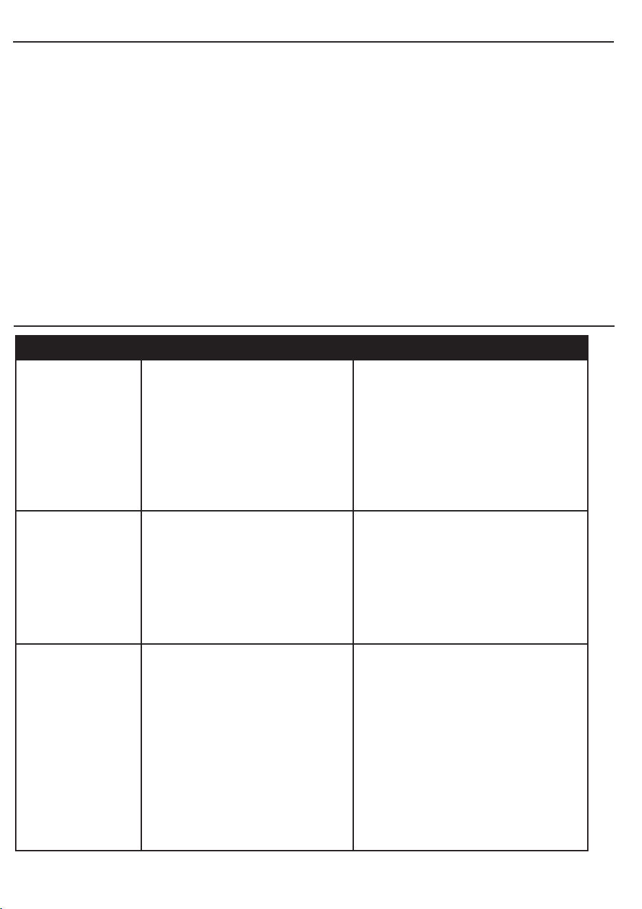
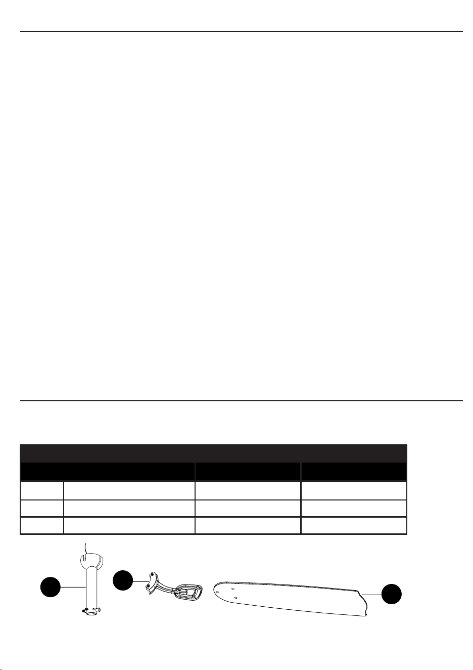
GARANTÍA
LISTA DE PIEZAS DE REPUESTO
Impreso en China
Para obtener piezas de repuesto, llame a nuestro Departamento de Servicio al Cliente al
1-800-643-0067 de lunes a jueves, de 8 a.m. a 6 p.m. y los viernes, de 8 a.m. a 5 p.m.,
hora estándar del Este.
36
El fabricante garantiza que este ventilador no presenta defectos de fabricación ni en los materiales
presentes en el momento del transporte desde la fábrica, durante un período limitado de por
vida a partir de la fecha de compra. Esta garantía es válida solo para el comprador original.
El fabricante acepta reparar dichos defectos sin cargo o, según nuestro criterio, reemplazar el
ventilador de techo por un modelo comparable o superior.
Para obtener el servicio de garantía, presente una copia del recibo de venta como comprobante
de la compra. Todos los costos de extracción y reinstalación son responsabilidad explícita
del comprador. Los daños en el ventilador de techo producidos por accidentes, uso indebido
o instalación incorrecta, o a causa de la colocación de accesorios de jación que no son del
fabricante del ventilador, serán responsabilidad del comprador. El fabricante no asume ningún
tipo de responsabilidad por la instalación del ventilador durante la garantía limitada de por vida.
Cualquier servicio realizado por una persona no autorizada invalidará la garantía.
Debido a las cambiantes condiciones climáticas, esta garantía no cubre cambios en el acabado
de latón, óxido, picaduras, deslustre, corrosión o descascarado. Los ventiladores con acabado de
latón mantienen su belleza cuando se los protege de las condiciones climáticas cambiantes. La
garantía no cubre los elementos de vidrio incluidos con este ventilador. Cualquier reemplazo de
piezas defectuosas para el ventilador de techo debe informarse dentro del primer año a partir de la
fecha de compra. Para conocer el saldo de la garantía, llame a nuestro Departamento de Servicio
al Cliente al 1-800-643-0067 para obtener la autorización para la devolución y las instrucciones de
envío, de modo que podamos reparar o reemplazar el ventilador de techo. Cualquier ventilador o
pieza devueltos con un embalaje incorrecto son responsabilidad única del comprador. No existe
otro tipo de garantía explícita. El fabricante rechaza cualquiera y todas las garantías implícitas.
La duración de cualquier garantía implícita que no pueda rechazarse se limita al período limitado
de por vida especicado en nuestra garantía. El fabricante no será responsable por daños
incidentales, resultantes o especiales que surjan en relación con el uso o el funcionamiento
del producto, excepto que la ley indique lo contrario. Esta garantía le otorga derechos legales
especícos pero puede tener también otros derechos que varían según el estado. Esta garantía
sustituye cualquier garantía previa.
NOTA: Una pequeña cantidad de “tambaleo” es normal y no se debe considerar como un defecto.
PIEZA DESCRIPCIÓN PIEZA #
Articulo #0747603 Articulo #0747604
E Ensamble de la varilla 102200-0289LO 102200-0289ZW
F Abrazadera del aspa 104000-0410LO 104000-0410ZW
G Aspa 108100-005079 108100-0049ZW
F
G
E