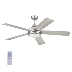
User Manual Harbor Breeze 42225 Ceiling Fan
PACKAGE CONTENTS
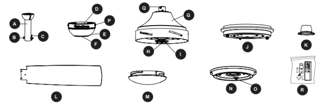
INITIAL INSTALLATION
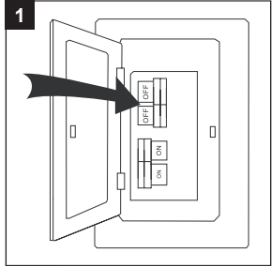
1. Turn off the circuit breakers and the wall switch to the fan supply line leads.
DANGER: Failure to disconnect the power supply prior to installation may result in serious injury or death.
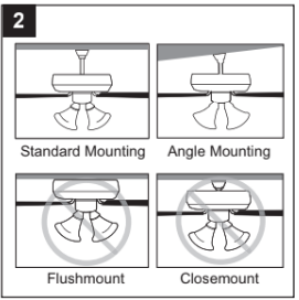
2. Determine the mounting method to use.
Standard mounting is best suited for ceilings 8 ft. or higher. For taller ceilings you may want to use a longer downrod (not included).
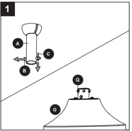
Angle mounting is best suited for angled or vaulted ceilings. A longer downrod is sometimes necessary to ensure proper blade clearance. Note: If using the angle mount, check to ensure the ceiling angle is not steeper than 16°.
Flushmount installation is not available for this item.
Closemount installation is not available for this item.
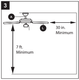
3. Ensure the blades (L) will be at least 30 in. from any obstructions. Also check the downrod (A) length to ensure the blades (L) will be at least 7 ft. above the floor.
4. Loosen all four preassembled mounting bracket screws (P), and completely remove the two mounting bracket screws (P) from the round holes of canopy (E). Set aside for later use. Turn the canopy in a counterclockwise direction. Detach mounting bracket (D) from canopy (E)

5. Attach mounting bracket (D) to outlet box (not included) using screws and washers provided with the outlet box.
CAUTION: It is very important you use the proper hardware when installing the mounting bracket (D) as this will support the fan.

STANDARD OR ANGLE MOUNTING INSTRUCTIONS
1. Remove the downrod clip (C) and downrod pin (B) from the downrod (A). Then partially loosen the set screws (Q) in the yoke at the top of the motor assembly (G).
2. Insert the downrod (A) through the canopy (E) and yoke cover (K). Feed the wires from the motor assembly (G) through the downrod (A).
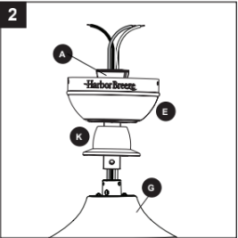
3. Slide the downrod (A) into the yoke of the motor assembly (G), align the holes, then re-install the downrod pin (B) and downrod clip (C). Secure with the two set screws (Q) and slide the yoke cover (K) down until it rests on top of the motor assembly (G).

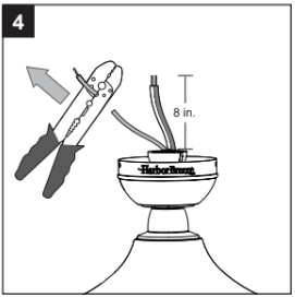
4. Depending on the length of downrod you use, you may need to cut the lead wires back to simplify the wiring. If you decide to cut back the lead wires, it is suggested you do so in the following manner: Take the lead wires and make sure you have pulled them all the way through the top of the downrod. Measure inches of lead wire, then cut the excess wire off with wire cutters (not included).
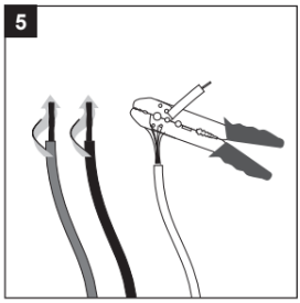
5. If you decided to cut back the lead wire in Step 4, strip in. of insulation from the end of the white wire. Twist the stripped ends of each strand of wire within the insulation with pliers (not included). Repeat the step for black and blue wires.
Note: If you did not cut back the lead wires in Step 4, Step 5 is not necessary and you may proceed to Step instead.
6. Install the ball end of the downrod (A) into the opening of the mounting bracket (D). Align the slot in the ball with the tab in the mounting bracket (D). Note: The downrod should not rotate if it is installed correctly.
DANGER: Failure to align the slot in the downrod (A) with the tab of the mounting bracket (D) may cause the fan to wobble or fall, which could result in serious injury or death.

WIRING
WARNING: To reduce the risk of fire, electrical shock or personal injury, wire connectors provided with this fan are designed to accept only one 12-gauge house wire and two lead wires from the fan. If your house wire is larger than 12-gauge and there is more than one house wire to connect to the two fan lead wires, consult an electrician for the proper size wire connectors to use.
CAUTION: Be sure the outlet box is properly grounded or that a ground (green or bare) wire is present.
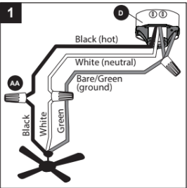
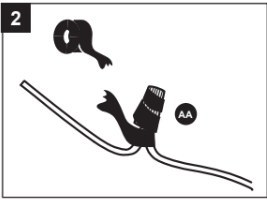
1. Use wire connectors (AA) to connect household supply and fan wires according to the diagram and these steps:
- Connect the Green wires from the downrod (A) and mounting bracket (D) to the Bare/Green supply wire.
- Connect the White wire from the fan to the White neutral) supply wire.
- Connect the Black wire from the fan to the Black hot)supply wire.
Important: The Black wire is power for the fan. The White wire is common/neutral. The Green wire is the ground wire. If supply wires are different colors than referred to above, a professional electrician should determine proper wiring.
2. Wrap electrical tape (not included) around each individual wire connector (AA) down to the wire.
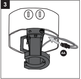
3. Turn the spliced/taped wires upward and gently push the wires and wire connectors (AA) into the outlet box.
WARNING: Ensure no bare wire or wire strands are visible after making connections. Place the Green and White wire connections on the opposite side of the outlet box from the Black wire connection.
FINAL INSTALLATION
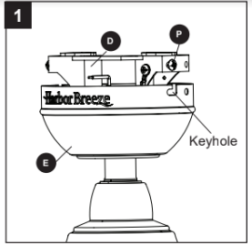
1. Align the canopy (E) over the loose mounting bracket screws (P) preassembled on mounting bracket (D). Place the keyholes of the canopy (E) onto the mounting bracket screws (P) and rotate the canopy (E) clockwise.
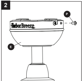
2. Secure the canopy (E) with the mounting bracket screws (P) previously removed (Step 4, page 8). Tighten all mounting bracket screws (P) securely.
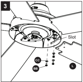
3. Insert blade (L) through slot in the side of the motor assembly (G). Align the holes of one blade (L) with three blade screw holes in underside of the motor assembly (G). Secure blade (L) with three blade screws (BB) and blade washers (CC). Repeat for the remaining blades (L).
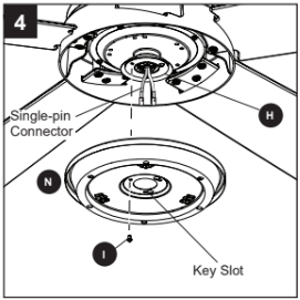
4. Remove one and loosen the other two fitter plate screws (I) but do not remove from fitter plate (H). Feed the single-pin connector through center hole in light pan. Align the two key slots in the light pan (N) with the loosened fitter plate screws (I). Place the light pan (N) over the two screws and turn the light pan (N) clockwise. Then tighten the two fitter plate screws (I). Re-install the fitter plate screw (I) that was removed in the previous step and tighten firmly.
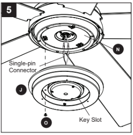
5. Remove one and loosen the other two light pan screws (O) from the underside of the light pan (N). Connect the single-pin connector from the fitter plate (H) to the single-pin connector from the light kit (J) blue to black and white to white. Align the key slot in the light kit (J) with the loosened screws in the light pan (N). Turn light kit (J) clockwise and replace the previously removed light pan screw (O). Tighten all screws.
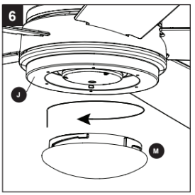
6. Lift the glass bowl (M) over the light kit (J) and turn in a clockwise direction until it is secure. CAUTION: Avoid cross-threading the glass during installation. Improper installation could cause the glass bowl (M) to be difficult to remove or fall, which could cause serious injury.
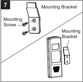
7. If desired, the mounting bracket in remote pack (R) can be installed to a wall using the provided mounting screws. The remote from remote pack (R) can be stored in the mounting bracket for easy access.
8. Turn on power supply to the fan.
Assembly is complete.
OPERATING INSTRUCTIONS
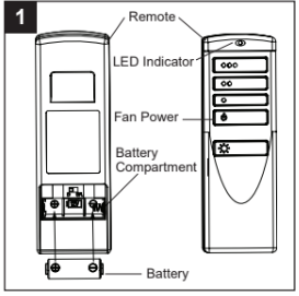
1. Remove the battery cover from the back of the remote found in remote pack (R). Insert the battery from remote pack (R) into the remote; ensuring the polarity of the battery matches the polarity indicated in the battery compartment -- positive (+) to positive (+) and negative to negative (-). Replace the battery cover and press the fan power button on the remote to ensure the LED indicator illuminates and the remote turns on the fan.
Note: If remote doesn’t turn on the fan, see TROUBLESHOOTING (page 18).
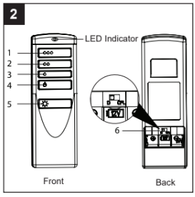
2. To operate the fan using the remote, press and release the following buttons:
1 - High fan speed
2 - Medium fan speed
3 - Low fan speed
4 - Fan Power - Turns the fan off.
Light Delay Off mode - Press and hold the fan power button (4) for five seconds, which will turn off light after one minute. The LED indicator on the remote will flash four times to confirm mode setting.
5 - Light Control:
Dimmable Bulbs - Press and hold light control to dim or brighten the lights.
Nondimmable Bulbs - Press light control to turn lights off and on.
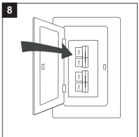
6 - D/CFL Switch: Switch should be set to “D” to correspond with dimmable bulbs (included). Flip to "CFL” if you change to nondimmable bulbs, which will disable the dimming function.
3. Using a ceiling fan will allow you to raise your thermostat setting in summer and lower your thermostat setting in winter without feeling a difference in your comfort.
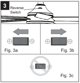
In warmer weather, push the reverse switch to the left which will result in downward airflow creating a wind chill effect (Fig 3a).
In cooler weather, push the reverse switch right which will result in upward airflow that can help move stagnant, hot air off the ceiling area (Fig 3b).
Important: Wait for the fan to stop before moving the reverse switch. The reverse switch must be set either completely right or left for the fan to function correctly. If the reverse switch is set in the middle position, the fan will not operate (Fig 3c).
CARE AND MAINTENANCE
At least twice each year, lower the canopy to check the downrod assembly, and then tighten all screws on the fan. Clean the motor housing with only a soft brush or lint-free cloth to avoid scratching the finish. Clean the blades with a lint-free cloth.
Total fixture wattage is 21 watts; do not attempt to replace LED.
Battery Replacement: Use a 23-amp, 12-volt alkaline battery. Exhausted batteries should be removed from remote. Non-rechargeable batteries should not be recharged. Do not dispose of batteries in fire, as they may explode or leak.
Important: Shut off the main power supply before you begin any maintenance tasks. Do not use water or a damp cloth to clean the ceiling fan.
TROUBLESHOOTING
POSSIBLE CAUSE - CORRECTIVE ACTION
The fan does not move.
1. The reverse switch is not engaged. - Firmly push the reverse switch completely left or right.
2. The wall switch is turned off. - Make sure the wall switch is turned on.
3. The power is off or the fuse breaker) is blown. - Turn the power on or check the fuse (breaker).
4. There is a faulty wire connection. - Turn the power off and check all connections at the ceiling outlet box.
The fan operates correctly, but the lights are not working.
1. The light kit wire plugs are not connected properly. - Ensure the single-pin connectors in the light kit are connected properly.
2. There is a faulty wire connection. - Turn the power off and check all connections at the ceiling outlet box.
The fan is noisy.
1. The blades are loose. - Check and tighten all screws that hold the fan blades to the blade arms and the motor.
2. There is a cracked blade. - Replace the cracked blade.
3. The wall control is not compatible with the fan. - Do not use a full range dimmer switch to control the fan speed.
4. The outlet box is not secure. - Ensure the outlet box is secured to the building structure.
5. The mounting bracket is not secure. - Ensure the mounting bracket is secured to the outlet box and that the screws are tight.
There is excessive wobbling.
1. The blades and/or blade arms are loose. - Check and tighten all screws that hold the fan blades to the blade arms and the blade arms to the motor.
2. The blades are unbalanced. - Switch one blade with a blade from the opposite side. Or balance the fan using a blade balancing kit (sold separately).
3. The fan mounting is not secure. - Turn off the power. Loosen the canopy and verify that the mounting bracket is secure to the electrical outlet box. The bracket must be flush without movement against the outlet box.
4. The fan is too close to the vaulted ceiling. - Use a longer downrod (sold separately) or move the fan to another location.
5. The set screw on the motor housing yoke is loose. - Lift the yoke cover and tighten the set screw to the yoke until secure.
Remote control does not work.
1. Power surge may have cleared memory and remote needs to be re-synced to the receiver. - Turn off the main power, then turn it back on. Within 30 seconds, press and hold the high and low speed buttons on the remote at the same time for seconds. The LED indicator will flash 3 times, signaling a successful synchronization. Once complete, the fan will start on the low speed with the light if applicable) off.
2. Battery in remote control needs to be replaced. - Insert new 12V battery in battery compartment of the remote control (see page 15).
3. Interference from another remote. - If there are several fans in proximity, turn power off to other fans and re-sync the remote (see Corrective Action 1 above).
LIMITED LIFETIME WARRANTY
The manufacturer warrants this fan to be free from defects in workmanship and materials present at time of shipment from the factory for a lifetime from the date of purchase by the original purchaser.
The retailer also warrants that all other fan parts, excluding any glass or plastic blades, to be free from defects in workmanship and material at the time of shipment from the factory for a period of one year after the date of purchase by the original purchaser. The manufacturer agrees to correct such defects without charge or at its option replace the ceiling fan with a comparable or superior model.
To obtain warranty service, present a copy of the receipt as proof of purchase. All costs of removing and reinstalling the product are your responsibility. Any damage to any part such as by accident or misuse or improper installation or by affixing any accessories, is not covered by this warranty. The manufacturer assumes no responsibility whatsoever for fan installation during the limited lifetime warranty. Any service performed by an unauthorized person will render the warranty invalid.
Due to varying climate conditions, this warranty does not cover any changes in brass finish, including rusting, pitting, corroding, tarnishing or peeling. Brass finishes of this type give their longest useful life when protected from varying weather conditions. Any glass provided with this fan is not covered by the warranty.
Any replacement of defective parts from the ceiling fan must be reported within the first year from the date of purchase. For the balance of the warranty, call our customer service department for return authorization and shipping instructions so that we may repair or replace the ceiling fan. Any fan or parts returned improperly is the sole responsibility of the purchaser. There is no other expressed warranty. The manufacturer disclaims any and all warranties. The duration of any implied warranty which cannot be disclaimed is limited to the time period as specified in the expressed warranty. The manufacturer shall not be liable for incidental, consequential, or special damages arising out of or in connection with product use or performance except as may otherwise be accorded by law. This warranty gives specific legal rights, and you may also have other rights which vary from state to state. This warranty supersedes all prior warranties.
Note: A small amount of “wobble” is normal and should not be considered a defect.