
Harbor Breeze
®
is a registered trademark
of LF, LLC. All Rights Reserved.
ITEM #0102524
MODEL #L2B1
EDENTON CEILING FAN
1
Español p. 20
®
Questions, problems, missing parts?
Before returning to your retailer, call our customer
service department at 1-800-643-0067, 8 a.m. - 6 p.m., EST, Monday - Thursday, 8 a.m. - 5
p.m., EST, Friday.
Lowes.com/harborbreeze
ATTACH YOUR RECEIPT HERE
Serial Number
Purchase Date
EB14425

2
Preparation ...........................................................................................................................
Initial Instructions ..................................................................................................................
Standard/Angle-Mounting Instructions ..................................................................................
Flushmount Instructions ........................................................................................................
Wiring Instructions ..............................................................................................................
Final Instructions ..................................................................................................................
Operating Instructions .............................................................................................................
Care and Maintenance .........................................................................................................
Safety Information ................................................................................................................
4
Package Contents ................................................................................................................
Hardware Contents ..............................................................................................................
3
4
5
6
7
9
10
11
14
15
Troubleshooting ...................................................................................................................
Limited Lifetime Warranty ....................................................................................................
15
18
Replacement Parts List ........................................................................................................
19
Lowes.com/harborbreeze
TABLE OF CONTENTS
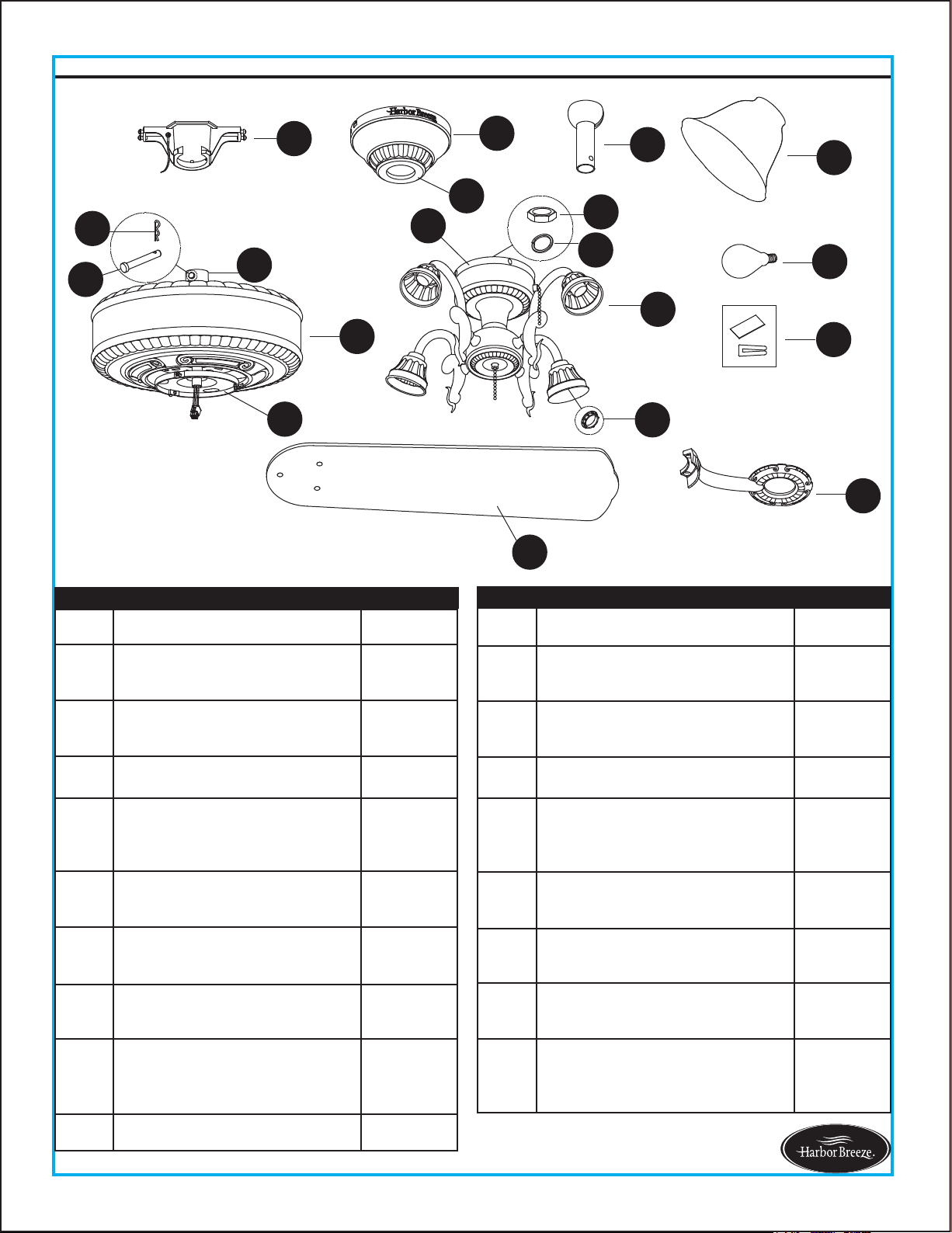
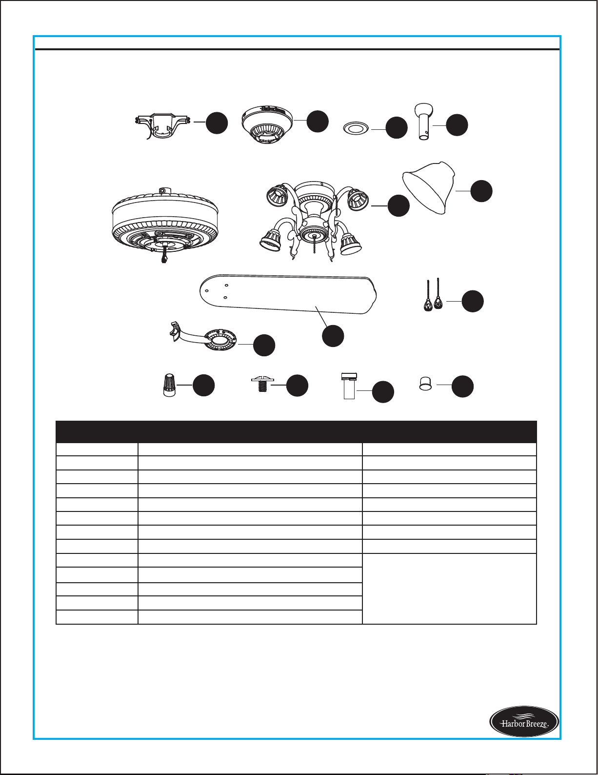
PACKAGE CONTENTS
3
Lowes.com/harborbreeze
A
B
C
D
K
N
S
J
Q
R
M
F
L
H
E
I
G
P
O
A Mounting Bracket 1
B Canopy 1
C
Canopy Cover
(preassembled on Canopy (B))
1
D Downrod Assembly 1
E
Coupling
(preassembled on Motor
Housing (H))
1
F Blade Iron 5
G Blade 5
H Motor Housing 1
I
Mounting Plate
(preassembled on Motor
Housing (H))
1
J Light Kit 1
PART DESCRIPTION QUANTIT
K Glass Bowl 4
L
Switch Housing
(preassembled to Light Kit (J))
1
M
Socket Ring
(preassembled to Light Kit (J))
4
N Bulb 4
O
Clevis Pin
(preassembled to Coupling (E))
1
P
Hairpin Clip
(preassembled to Clevis Pin(O))
1
Q
Hex Nut
(preassembled to Light Kit (J))
1
R
Spring Washer
(preassembled to Light kit (J))
1
S Balance Kit 1
PART DESCRIPTION QUANTIT
4
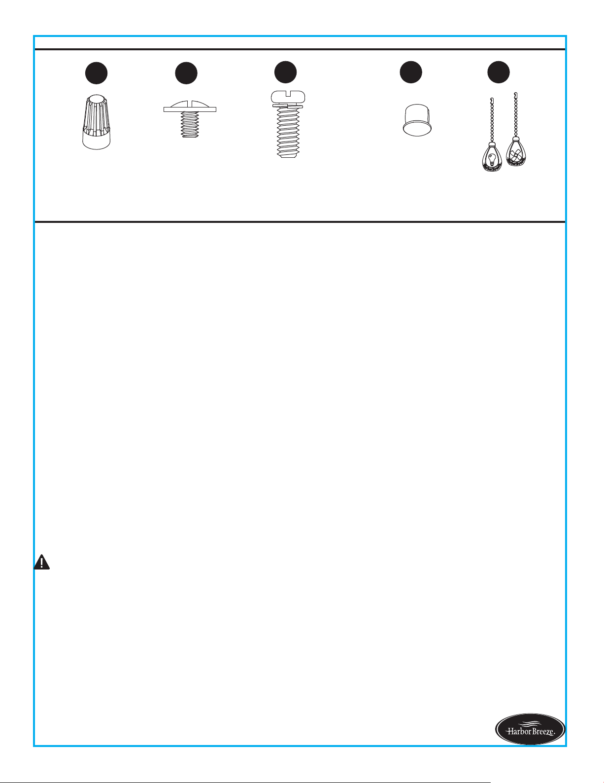
HARDWARE CONTENTS (not shown actual size)
SAFETY INFORMATION
Lowes.com/harborbreeze
READ AND SAVE THESE INSTRUCTIONS
All electrical connections must comply with local codes, ordinances or the National Electric Code (NEC).
Contact your municipal building department to inquire about your local codes, permits and/or inspections.
Turn off electricity at main fuse box (or circuit breaker box) before beginning installation by removing fuse or
by removing th fuse or by switching off circuit breaker.
Do not connect this fixture to an electrical system that does not provide a means for equipment grounding.
Never use a fixture in a two-wire system that is not grounded.
If you are not sure your lighting system has a grounding means, do not attempt to install this fixture. Contact
a qualified, licensed electrician for information regarding proper grounding methods as required by the local
electrical code in your area.
Make sure the installation site you choose allows a minimum clearance of 7 ft. from the blades to the floor
and at least 30 in. from the ends of the blades to any obstruction.
If a dimmer control switch is used with this fixture, obtain professional advice to determine the correct type
and electrical rating required.
The lighting fixture must be positioned so there is at least 1.64 ft. between the bulb and any illuminated
surface.
For supply connections, if the conductor of a fan is identified as a grounded conductor, then it should be
connected to a grounded conductor power supply. If the conductor of a fan is identified as an ungrounded
conductor, then it should be connected to an ungrounded conductor power supply. If the conductor of a fan
is identified for equipment grounding, then it should
be connected to an equipment-grounding conductor.
Connection of the bare or green fixture ground wire to the black or white house wires may allow metal parts
of the fixture to carry electrical currents. Under this condition anyone coming in contact with the fixture will
receive electrical shock, which could cause serious injury or death.
Installing a fixture into an electrical system without a proper grounding means could allow metal parts of the
fixture to carry electrical currents. If any of the fixture wires, wire connections or splices are broken, cut or
loose during the mounting or normal operation of the fixture, under such conditon, anyone coming in
contact with the fixture is subject to electrical shock, which could cause serious injury or death.
Be careful not to damage or cut the wire insulation (covering) during fixture installation. Do not permit wires
to have contact with any surface having a sharp edge. Doing so may damage or cut the wire insulation,
which could cause serious injury or death from electric shock.
Please read and understand this entire manual before attempting to assemble, operate or install the product.
DANGER
AA
BB
CC
DD EE
Wire Connector
Qty. 4
Blade Screw
Qty. 15 + 1 extra
Motor Screw
Qty. 10 (5 preassembled)
+ 1 extra
Fob
Qty. 2
Plastic Plug
Qty. 1
5
SAFETY INFORMATION
Lowes.com/harborbreeze
Risk of fire. Most dwellings built before 1985 have supply wire rated for 140°F. Consult a qualified
electrician before installation.
To reduce the risk of fire or electric shock, do not use this fan with any solid state fan speed device
or variable speed control.
To reduce the risk of personal injury, do not bend the blade brackets when installing the brackets,
balancing or cleaning the fan.
Do not insert foreign objects in between rotating fan blades.
Do not install or use the fan if any part is damaged or missing.
To reduce the risk of fire, electric shock or personal injury, mount to metal outlet box marked
'ACCEPTABLE FOR FAN SUPPORT OF 35 LBS OR LESS' and use mounting screws provided
with the outlet box and/or support directly from building structure. Most outlet boxes commonly
used for t
he support of luminaries are not acceptable for fan support and may need to be replaced.
Consult a qualified electrician if in doubt.
Before servicing or cleaning the unit, switch power off at the service panel and lock the service
disconnecting means to prevent power from being switched on accidentally. When the service
disconnecting means cannot be locked, securely fasten a prominent warning dev
ice, such as a tag,
to the service panel.
Do not use bulbs having a wattage greater than the maximum value stated on the fixture and in
this manual. Using a higher wattage bulb than specified will increase fixture temperature and
increase risk of fire.
Estimated Assembly Time: 45 minutes
CAUTION
PREPARATION
Before beginning assembly of product, make sure all parts are present. Compare parts with package
contents list and hardware contents list. If any part is missing or damaged, do not attempt to
assemble the product.
Tools Required for Assembly (not included): Philips Screwdriver, Step Ladder, Tape, Pliers and Wire
Cutters.
WARNING
7 ft. MIN.
30 in.
MIN.
2b
6
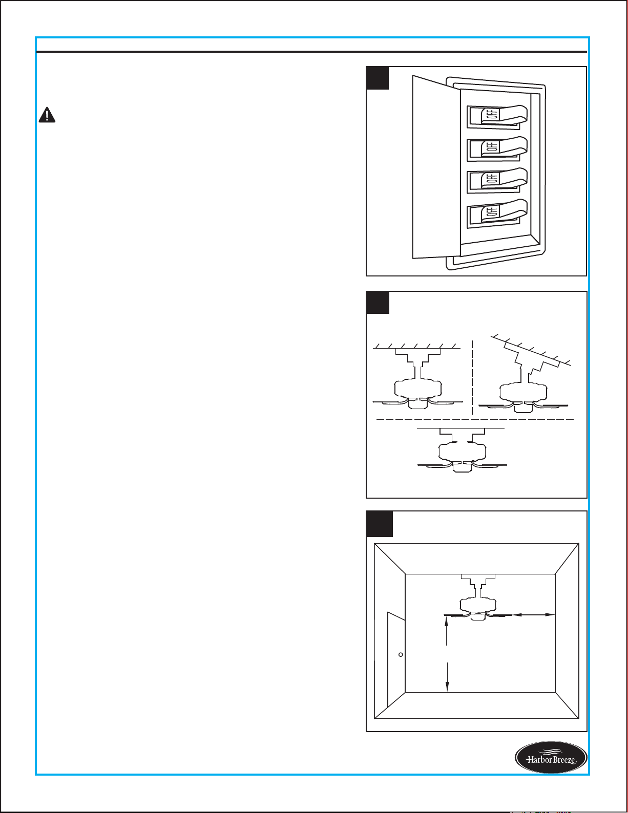
INITIAL INSTALLATION INSTRUCTIONS
1. Turn off circuit breakers and wall switch to the fan
supply line leads.
2a. Choose the desired mounting method:
2b. Make sure the installation site you choose allows a
minimum clearance of 7 ft. from the blades to the
floor and at least 30 in. from the ends of the blades
to any obstruction.
A. Standard Mounting: Standard mounting is best
suited for ceilings 8 ft. or higher. For taller ceilings you
may want to use a longer downrod (not included).
Lowes.com/harborbreeze
1
DANGER: Failure to disconnect power supply prior to
installation may result in serious injury or death.
B. Angle Mounting: Angle-style mounting is best suited
for angled or vaulted ceilings. A longer downrod is
sometimes necessary to ensure proper blade clearance.
If using the angle mount, make sure the ceiling angle is
not steeper than 20°.
C. Flush Mounting: Flushmount installation is used for
ceiling less than 8 ft. high.
2
A
B
C
7
Lowes.com/harborbreeze
1. Place downrod assembly (D) through canopy (B) and
canopy cover (C).
INITIAL INSTRUCTIONS
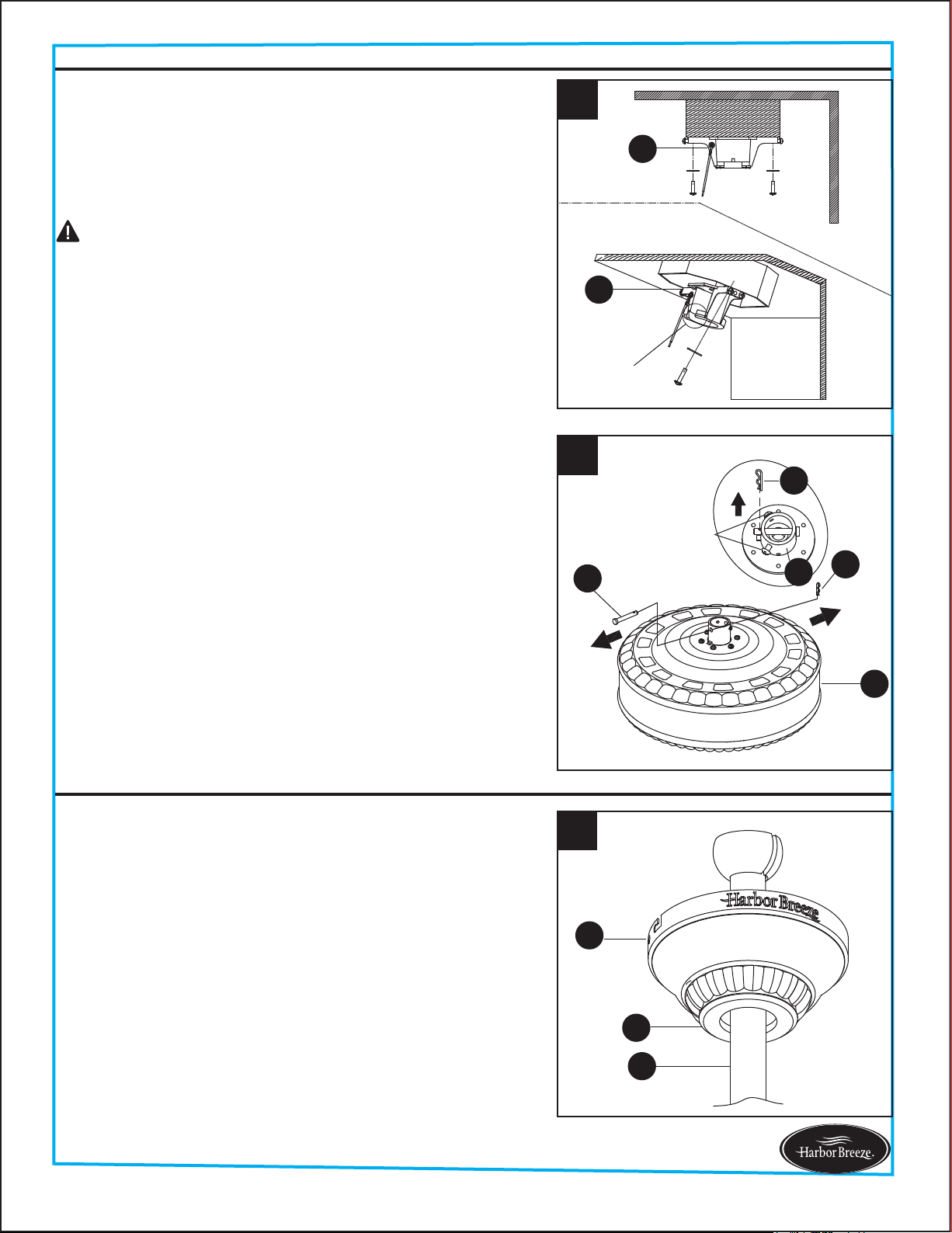
STANDARD/ANGLE-MOUNTING INSTRUCTIONS
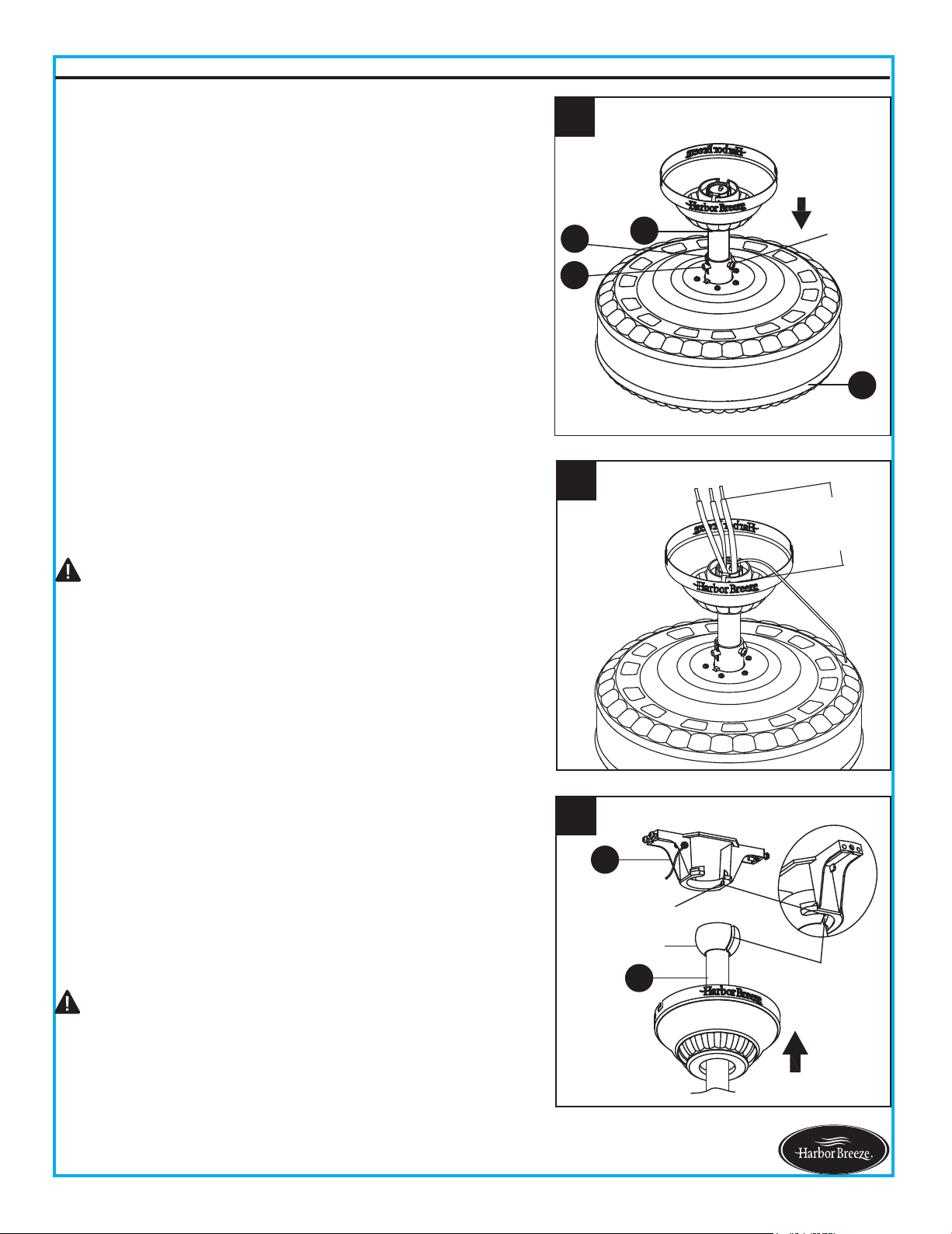
4. Remove the hairpin clip (P) and clevis pin (O) from the
coupling (E) preassembled on motor housing (H).
Retain for later use.
3. Check existing outlet box (not included) to ensure it is
securely fastened to at least two points in a structural
ceiling member and can support the full weight of the
fan. Once verified, install mounting bracket (A) to the
outlet box using the screws and washers provided with
the outlet box.
Loosen the two screws preassembled in coupling (E),
but do not remove them.
For STANDARD/ANGLE-MOUNTING INSTRUCTIONS,
proceed to Step 1 below. For FLUSHMOUNT
INSTRUCTIONS, skip to page 9.
3
Open End
A
A
Note: If using the angle mount, make sure open end of
mounting bracket (A) is installed facing the higher point
of the ceiling.
Note: Make sure to keep loose hardware separate to
avoid confusion during installation.
DANGER: A loose outlet box can cause the fan to wobble
and increase the fan's potential to fall, which could result
in serious injury or death.
B
C
D
1
4
P
P
H
O
Screw
E
8
STANDARD/ANGLE-MOUNTING INSTRUCTIONS
Lowes.com/harborbreeze
4. Carefully lift assembly and rest the hanger ball of
downrod assembly (D) on the mounting bracket (A)
attached to the outlet box. Be sure the slot in the
hanger ball is lined up with the tab on the mounting
bracket (A). This will leave hands free for the wiring
process.
Proceed to WIRING INSTRUCTIONS on page 10.
DANGER: Be careful when aligning the tab to the
slot! If not fully engaged, there is a possibility of the fan
falling, which may result in serious injury or death.
CAUTION: Ensure all screws are tight before moving
onto the next step.
3. Cut off excess fixture wires, leaving approximately 6 to 9
inches above the top of the downrod assembly (D). Strip
1/2 inch of insulation from the end of each fixture wire.
6 to 9 in
3
Screw
2
D
H
P
O
2. Feed power wires from motor housing (H) through
downrod assembly (D), then insert downrod assembly
(D) into the coupling (E) on motor housing (H).
Align the hole on downrod assembly (D) to hole on
coupling (E), then re-install clevis pin (O). Re-attach
hairpin clip (P) into clevis pin (O) until it snaps into place,
then tighten the two previously loosened screws.
4
A
D
Hanger Ball
Tab
Slot
A
B
3
9
Lowes.com/harborbreeze
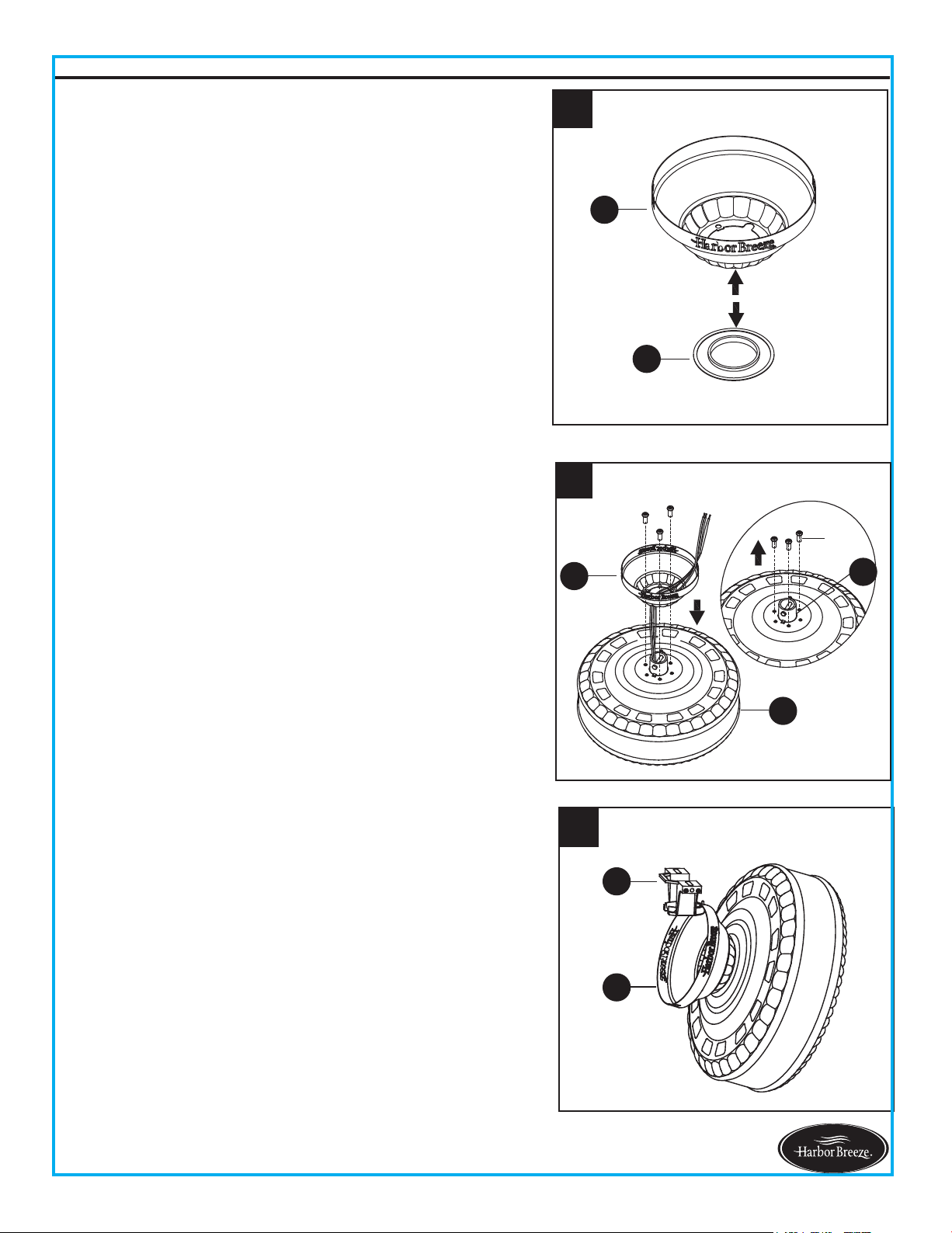
2. Remove the three Phillips-head screws preassembled
near coupling (E) on the motor housing (H). Guide
power wires from motor housing (H) through the base
of the canopy (B), then attach canopy (B) to motor
housing (H) with previously removed screws. Tighten
securely.
3. Raise assembly and temporarily place one side of
canopy (B) onto hook of mounting bracket (A). This
will leave hands free for the wiring process.
1. Press out on the inner edges of the canopy cover (C)
from inside the canopy (B) until it releases from the
canopy (B).
Note: Flushmount installation will not use canopy cover
(C), downrod assembly (D), clevin pin (O), hairpin clip (P)
or coupling screws.
FLUSHMOUNT INSTRUCTIONS
B
E
H
2
Screw
1
B
C
Proceed to WIRING INSTRUCTIONS on next page.
10
Lowes.com/harborbreeze
WARNING: To avoid possible electrical shock, be sure electricity is turned off at the main fuse box
before hanging.
WARNING: If you are not sure if the outlet box is grounded, contact a licensed electrician for advice,
as it must be grounded for safe operation.
WARNING: If house wires are different colors than referred to in the following steps, stop
immediately. A professional electrician is recommended to determine proper wiring.
WARNING: If you feel that you do not have enough electrical wiring knowledge or experience,
have the fan installed by a licensed electrician.
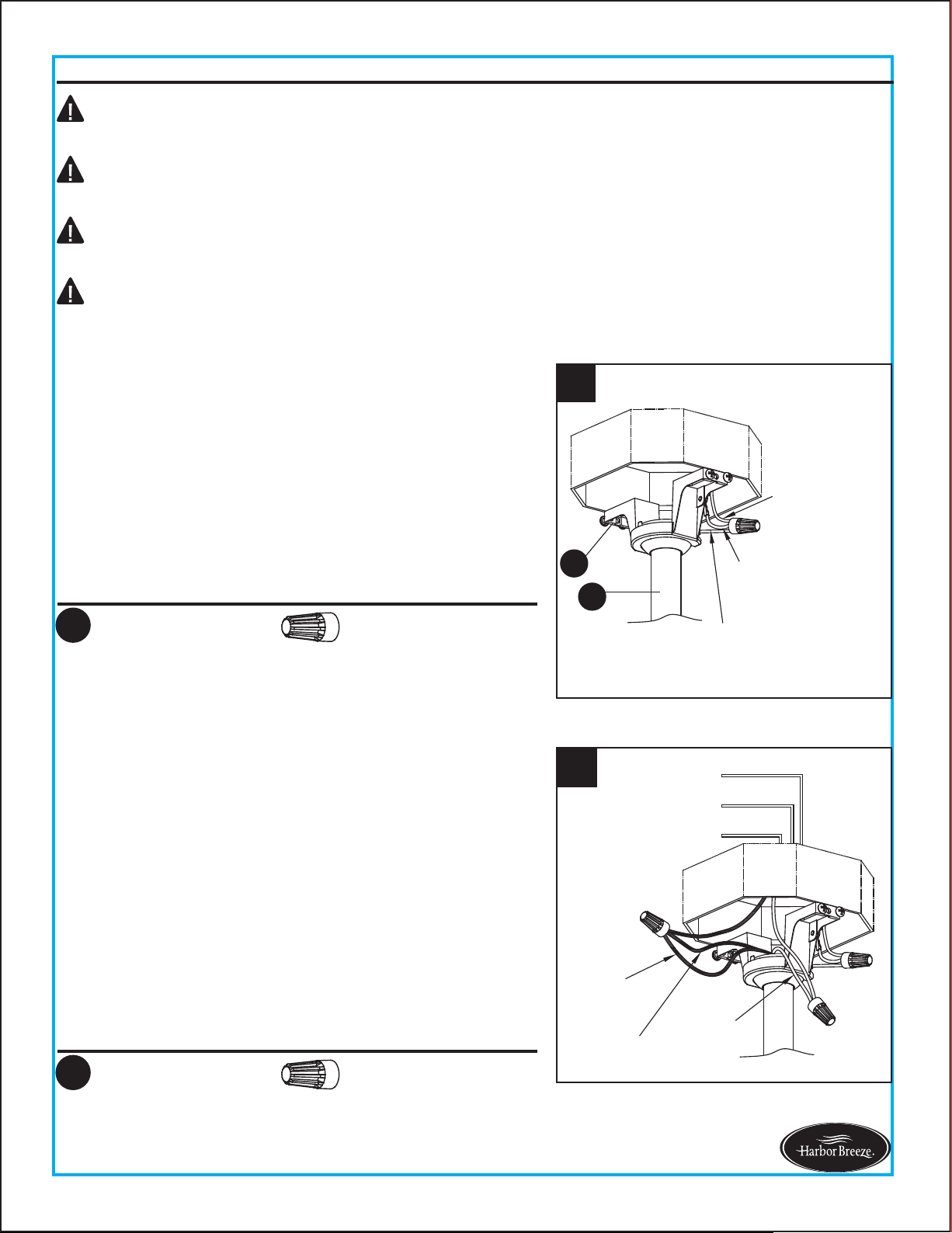
1. Connect the GREEN wires from the hanger ball of
downrod assembly (D) and mounting bracket (A) to the
supply ground (GREEN or bare) wire. Securely connect
wires using wire connector (AA).
2. Securely connect the fan WHITE wire to the supply
WHITE wire using wire connector (AA). Securely
connect the fan BLACK and BLUE wires to the supply
BLACK wire using wire connector (AA).
Note: Flushmount installation will not use the Green wire
from the downrod assembly (D).
WIRING INSTRUCTIONS
Hardware Used
AA Wire Connector x 1
Hardware Used
AA Wire Connector x 2
2
Black
Fan Wire
Blue
Fan Wire
BLACK
GREEN
WHITE
White
Fan Wire
1
Supply
Ground Wire
Green Wire from
Mounting Bracket
Green Wire from
Hanger Ball
A
D
Note: This is only one way to wire the fan; consult a
qualified electrician if it is not applicable to your home.
Note: The BLACK wire is hot power for the fan. The
WHITE wire is common for the fan and light. The BLUE
wire is hot power for the light. The GREEN wire is the
ground wire.
BLACK
BLUE
WHITE
GREEN
Outlet Box
3
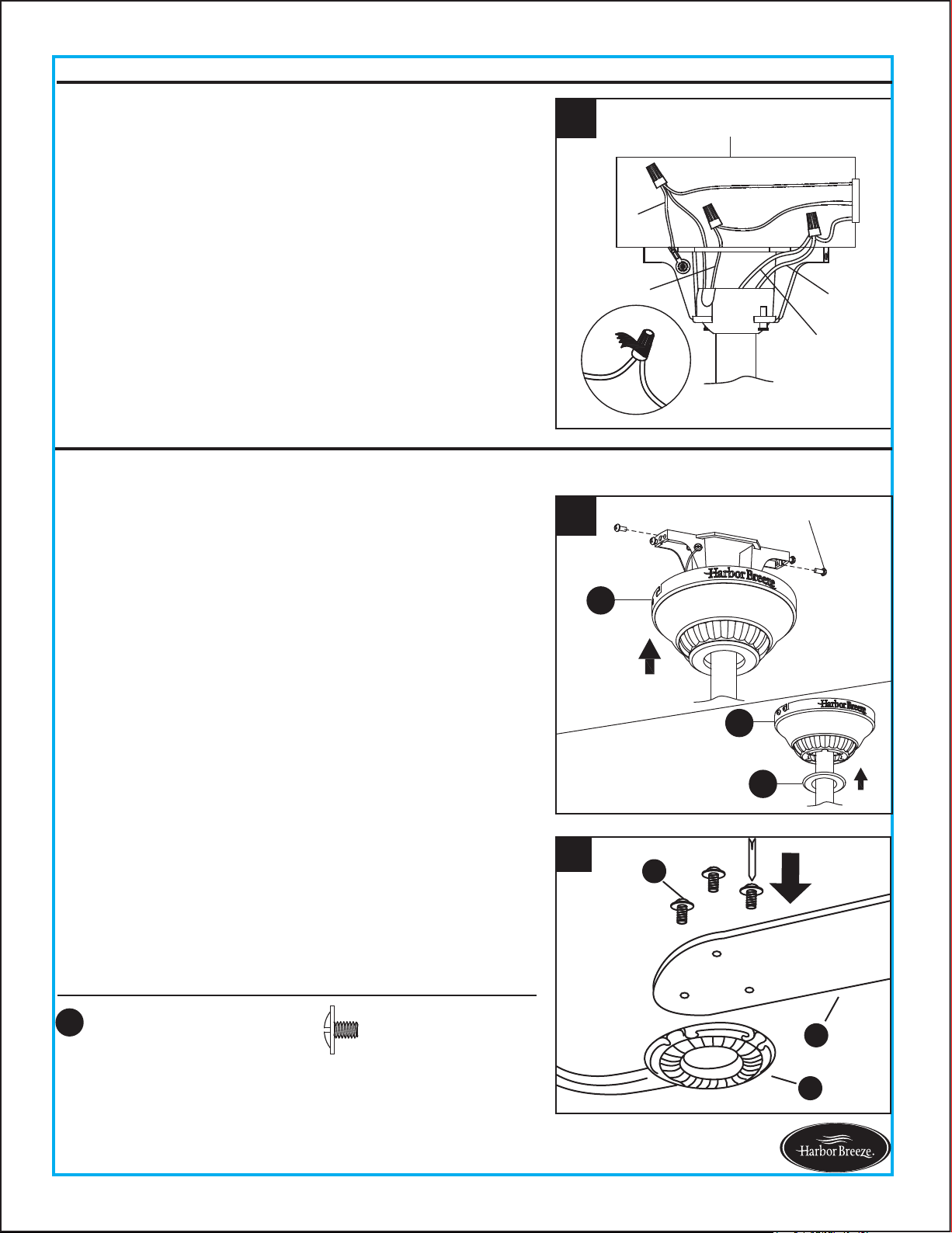
3. Wrap electrical tape (not included) around each wire
connector (AA) and make sure no bare wire or wire
strands are visible after making connections.
Note: Flushmount installation will not use the downrod assembly (D) or canopy cover (C) as shown.
FINAL INSTRUCTIONS
11
Lowes.com/harborbreeze
1. Loosen (but do not remove) the two preassembled
mounting screws on mounting bracket (A) that align
with the slotted holes on canopy (B). Remove the other
two mounting screws.
Lift canopy (B) up so slotted holes engage loosened
screw heads on mounting bracket (A), then twist canopy
(B) clockwise. Re-install previously removed mounting
screws, then tighten all screws securely.
2. Position one blade iron (F) under blade (G). Insert three
blade screws (BB) through blade (G) and into blade iron
(F). Tighten each blade screw (BB) evenly, starting with
the center blade screw (BB). Repeat for the remaining
blade assemblies.
Note: If the canopy cover (C) is loosened during installation,
press it to the inner edge of the canopy (B).
WIRING INSTRUCTIONS
2
BB
G
F
x 15
BB
Blade Screw
Hardware Used
Then, turn wires upward and carefully push them into
the outlet box; make sure the WHITE and GREEN
connections are on one side and the BLACK connections
are on the other side.
1
Screw
B
B
C
12
FINAL INSTRUCTIONS
Lowes.com/harborbreeze
4
I
Screw
Hardware Used
x 10
CC
Motor Screw
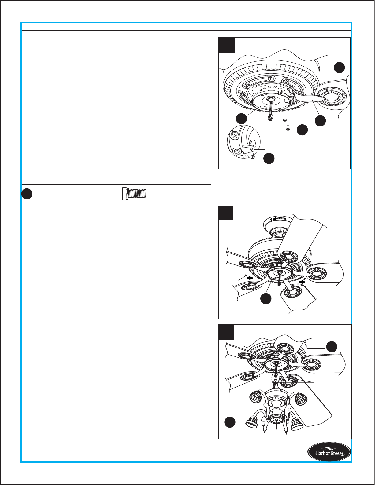
3. Remove the 5 motor screws (CC) preassembled at the
bottom of motor housing (H), discarding the
preassembled motor blocks but retaining the motor
screws (CC) for later use.
Position one completed blade assembly under motor
housing (H). Align the holes on the motor housing (H)
and blade iron (F), then adjust the slot on the
preassembled mounting plate (I) over the holes. Using
2 previously removed motor screws (CC), insert
them through the slot on the mounting plate (I) into
blade iron (F) and motor housing (H), and partially
tighten. Repeat for the remaining blade assemblies by
using the previously removed motor screws (CC) as
well as those in the hardware pack, then securely
tighten all motor screws (CC).
5. To install the light kit (J), attach the connector
preassembled on light kit (J) to the connector
preassembled on motor housing (H).
Note: The two connectors have keyholes that must be
mated correctly before they can be engaged.
4. Remove three screws preinstalled on the mounting plate
(I) and save them for later use.
Note: Make sure to keep loose hardware separate to
avoid confusion during installation.
To install the fan with the light kit (I), proceed to step 5
below. If you wish not to install the light kit (I), skip to
step 8 on page 13.
5
J
H
9-pin
connections
CC
CC
F
H
I
Motor Block
3
13
FINAL INSTRUCTIONS
Lowes.com/harborbreeze
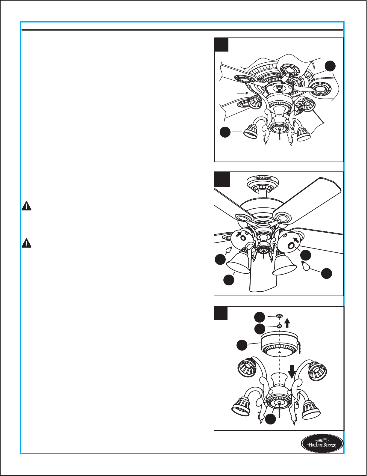
Remove socket ring (M) from each socket on light kit (J).
Slide glass bowl (K) to each socket, securing with socket
rings (M). Then, install bulbs (N) into sockets.
7.
For assembly without the light kit (J), remove the hex nut
(O) and spring washer (P) from the top of switch housing
(L). Disassemble light kit (J) from switch housing (L) and
discard. Save hardware for later use.
8.
7
M
N
K
N
6. Attach the switch housing (L) with light kit (J) to the
mounting plate (I) using the three screws previously
removed (step 4, page 12). Tighten securely.
6
J
I
Screw
Proceed to Step 10 (page 14).
CAUTION: Do not overtighten socket rings (M), as this
could crack or break the glass bowls (K).
CAUTION: When replacing bulbs (N), ensure wattage is
below 190 watts. If you replace bulbs with more than 190
watts, the fixture will dim the lights to 190 watts courtesy
of an energy-saving wattage limiter. After a period of time
from the power to the fan being turned off, there might be
a delay of about 0.5-1 second before the light turns on
due to this limiter.
8
J
L
P
O
14
FINAL INSTRUCTIONS
Lowes.com/harborbreeze
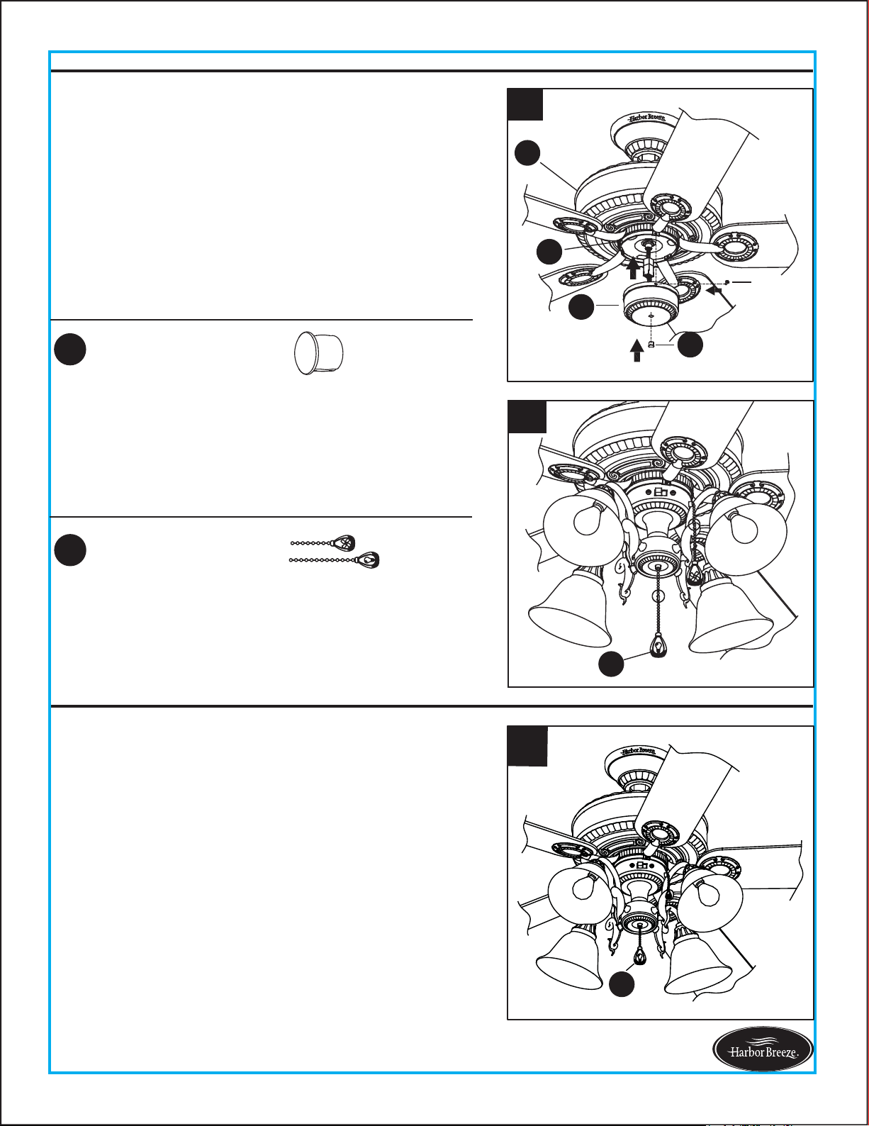
10. Connect the fobs (EE) to the appropriate pull chains.
For assembly without the light kit, you can discard the
fob (EE) with the light image.
9
I
Screw
L
DD
H
Hardware Used
EE
x 2
Fob
Attach the connector from the switch housing (L) to
connector from the motor housing (H). Then, attach
the switch housing (L) to the mounting plate (I) using
the three screws previously removed (step 4, page
12). Tighten securely, then attach plastic plug (DD) into
hole in the middle of switch housing (L).
9.
Hardware Used
DD
x 1
Plastic Plug
10
EE
The fob (EE) marked with a fan image is for motor
speed control: High, Medium, Low and Off. Pull once
for each position.
1.
The fob (EE) marked with a lamp image controls the
light, either ON or OFF with each pull of the chain.
1
EE
OPERATING INSTRUCTIONS
Note: The two connectors have keyholes that must be
mated correctly before they can be engaged.
2
15
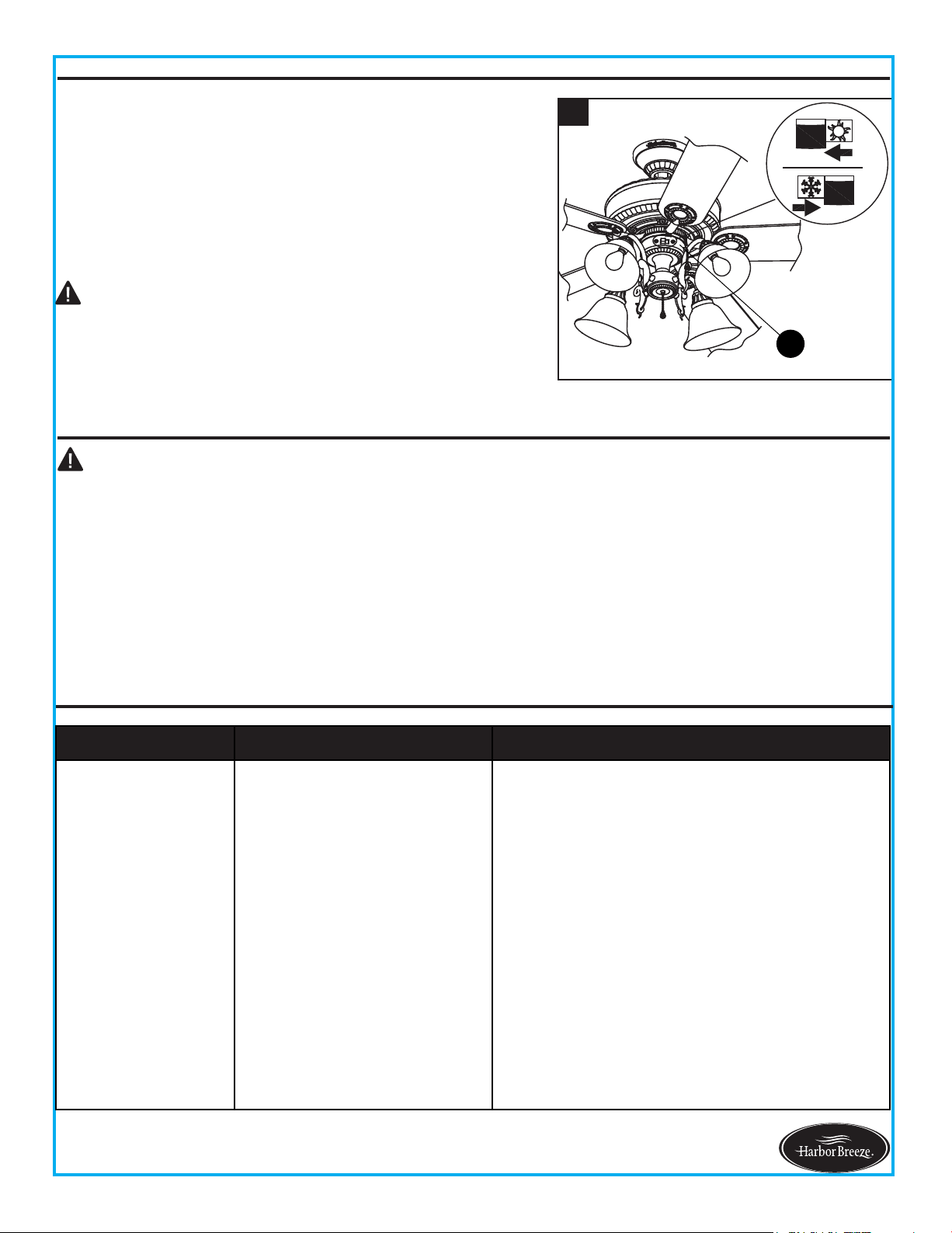
NOTE: Make sure reverse switch is firmly in left or right
position. Fan will not operate when switch is in the middle.
2.
When the season changes, you may want to change the
direction the fan spins. In warmer weather,
counterclockwise rotation creates a downward air flow,
which cools the air. Push the reverse switch located on
switch housing (L) LEFT and see a SUN icon. In cooler
weather, clockwise rotation creates an upward air flow,
which moves hot air from the ceiling into room. Push the
reverse switch RIGHT and see a SNOWFLAKE icon.
CARE AND MAINTENANCE
OPERATING INSTRUCTION
$WOHDVWWZLFHHDFK\HDUWLJKWHQDOOVFUHZVDQGORZHUFDQRS\WRFKHFNPRXQWLQJSODWHVFUHZV
&OHDQIDQKRXVLQJZLWKRQO\DVRIWEUXVKRUOLQWIUHHFORWKWRDYRLGVFUDWFKLQJWKHILQLVK&OHDQEODGHV
ZLWKDOLQWIUHHFORWK<RXPD\RFFDVLRQDOO\DSSO\DOLJKWFRDWRIIXUQLWXUHSROLVKWRZRRGEODGHVIRU
added protection.
%XOE5HSODFHPHQW8VHIRXUZDWWPD[W\SH$LQFDQGHVFHQWEXOEV&)/EXOEVDUHQRW
recommended for this item.
/RZHVFRPKDUERUEUHH]H
Important:6KXWRIIPDLQSRZHUVXSSO\EHIRUHEHJLQQLQJDQ\PDLQWHQDQFH'RQRWXVH
water or a damp cloth to clean the ceiling fan.
CAUTION:7XUQRIIDQGZDLWIRUIDQWRVWRSEHIRUH
moving the reverse switch.
L
PROBLEM
CORRECTIVE ACTIONPROBABLE CAUSEPROBLEM
1. Set screws are loose. 1. Tighten all set screws.
2. Using nonapproved speed
control.
2. Some fan motors are sensitive to signals
from solidstate variEle speed controls. 'O
NOT USE a solidstate variaEle speed control.
3. Normal noise.
3. Allow "Ereakin" period of 2 hours. Most
noises associated with a new fan will disappear
after this period.
. Wire connectors inside
switch housing rattling.
. &heck to make sure wire connectors in
switch housing are not rattling against each
other or against the interior wall of the switch
housing.
5. &racked Elade. 5. Replace Elades.
Fan sounds noisy.
TROUBLESHOOTING
16
TROUBLESHOOTING
Lowes.com/harborbreeze
1. Hanger bracket and/or
ceiling outlet box is not
securely fastened.
1. Tighten the hanger bracket screws to the
outlet box, and/or secure outlet box.
2. Set screw in downrod
assembly is loose.
2. Tighten the set screw in the downrod
assembly.
3. Fan hanger ball is not
properly seated in canopy tabs.
3. Turn power off, support the fan very carefully,
and check that the hanger ball is properly seated.
4. Set screw in motor coupling
is loose.
4. Raise motor coupling up and tighten set
screws securely.
5. Blade is loose. 5. Check that all blades are screwed firmly into
blade holders.
Fan wobbles.
PROBLEM CORRECTIVE ACTION
6. The distance from canopy
to ceiling is too great.
6. Make sure upper canopy is a short distance
from ceiling. It should not touch the ceiling.
7. Faulty light bulb installation. 7. Make sure light bulb is tight in socket and
does not touch glass shade.
8. Glass is not secure. 8. Secure the glass.
PROBABLE CAUSE
6. Blade holders are loose. 6. Check to be sure the fan blade irons sea
t
firmly and uniformly on the surface of the motor.
If flanges are seated incorrectly, loosen the
flange screws and retighten.
7. Blade out of balance.
7. Interchange two adjacent blades; this will
redistribute the weight and possibly result in
smoother operation. Or, refer to the instructions
inside the balance kit (S).
8. Fan too close to vaulted
ceiling.
8. Lower or move fan. Extension downrods may
be or
dered.
9. Transition to different speed.
9. When switching from medium to low speed,
you may notice some fan wobble in the fan.
When the fan stabilizes at low speed, wobble
should disappear.
10. Fan not securely mounted. 10. Make sure canopy and mounting bracket
are tightened securely to ceiling joist.
Fan sounds noisy.
17
TROUBLESHOOTING
Lowes.com/harborbreeze
1. Power turned off, fuse blown
or circuit breaker tripped.
1. Turn power on, replace fuse or reset breaker.
3. Motor reversing switch not
engaged.
3. Push switch firmly right or left. Fan will not
operate when switch is in the middle.
4. Pull chain switch not "on". 4. Pull switch chain.
1. Wrong wire connection. 1. Refer to Step 1, page 10 to ensure all wire
connections were done correctly.
2. Bulb is burned
out. 2. Replace the bulbs.
Fan does not start.
Light does not work.
2b. Check the plug connection in the switch
housing.
2a. Turn power off and loosen canopy; check
all connections according to section WIRING
INSTRUCTIONS on page 10.
2. Loose wire connections or
wrong connections.
PROBLEM PROBABLE CAUSE CORRECTIVE ACTION

LIMITED LIFETIME WARRANTY
The manufacturer warrants this fan to be free from defects in workmanship and material present at
time of shipment from the factory for life (with limitations) from the date of purchase. This warranty
applies only to the original purchaser. The manufacturer agrees to correct such defect at no charge
or, at our option, replace the ceiling fan with a comparable or superior model.
To obtain warranty service, present a copy of your sales receipt as proof of purchase. All cost of
removal and reinstallation are the expressed responsibility of the purchaser. Any damage to the ceiling
fan by accident, misuse or improper installation, or by affixing accessories not produced by this
warranty, are at the purchaser’s own responsibility. The manufacturer assumes no responsibility
whatsoever for fan installation during the limited lifetime warranty. Any service performed by an
unauthorized person will render the warranty invalid.
Due to varying climatic conditions, this warranty does not cover changes in brass finish, rusting,
pitting, tarnishing, corroding or peeling. Brass finish fans maintain their beauty when protected from
varying weather conditions.
NOTE: A small amount of “ wobble ” is normal and should not be considered a defect.
Any replacement of defective parts for the ceiling fan must be reported within the first year from the
date of purchase. For the balance of the warranty, call our customer service department at 1-800-643-
0067 for return authorization and shipping instructions so that we may repair or replace the ceiling fan.
Any fan or parts returned improperly packaged is the sole responsibility of the purchaser. There is no
further expressed warranty. The manufacturer disclaims any and all implied warranties.
The duration of any implied warranty which can not be disclaimed is limited to the lifetime limited
period as specified in our warranty. The manufacturer shall not be liable for incidental, consequential
or special damages arising at or in connection with product use or performance except as may other
wise be accorded by law. This warranty gives you specific legal rights, and you also have other rights
which vary from state to state. This warranty supersedes all prior warranties.
18
Lowes.com/harborbreeze
A101-0346184
A108-0260184
A103-0156184
A143-0186184
A141-0138001
A187-0179184
A182-0069036
B168-0382005
Printed in China
19
REPLACEMENT PARTS LIST
Lowes.com/harborbreeze
For replacement parts, call our customer service department at 1-800-643-0067, 8 a.m. - 6 p.m.,
EST, Monday - Thursday, 8 a.m. - 5 p.m., EST, Friday.
A
B
C
J
K
EE
G
F
AA
BB
CC
DD
D
Part Description Part#
A Mounting Bracket A102-0132005
B Canopy
C Canopy Cover
D Downrod Assembly
F Blade Iron
G Blade
J Light Kit
K Glass Bowl
AA Wire Connector
BB Blade Screw
CC Motor Screw
DD Plastic Plug
EE
Fob
Harbor Breeze ® is a registered trademark of LF, LLC. All Rights Reserved.