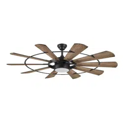
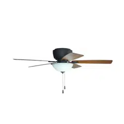
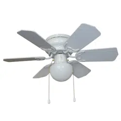
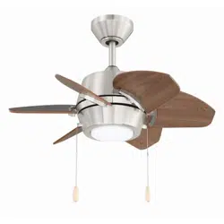
OPERATING INSTRUCTIONS for Ceiling Fan
PACKAGE CONTENTS
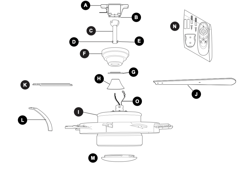
A. Mounting Bracket
B. Canopy Mounting Screw (preassembled)
C. Downrod
D. Pin (preassembled)
E. Clip (preassembled)
F. Canopy
G. Canopy Cover
H. Yoke Cover
I. Motor Assembly
J. Blade
K. Blade Bracket
L. Blade Bar
M. Shade
N. Remote Pack
O. Safety Cable (preassembled)
IMPORTANT REMINDER: You must use the parts provided with this fan for proper installation and safety.
PREPARATION
Before beginning assembly of product, make sure all parts are present. Place motor on carpet or on foam to avoid damage to finish. Compare parts with package contents list and hardware contents list. If any part is missing or damaged, do not attempt to assemble the product.
Estimated Assembly Time: 120 minutes
Tools Required for Assembly (not included): Electrical Tape, Phillips Screwdriver, Pliers, Safety Glasses, Stepladder, Wire Strippers and Precision Screwdriver (0 x 2 in.).
Helpful Tools (not included): AC Tester Light, Tape Measure, Do-It-Yourself Wiring Handbook and Wire Cutters.
INITIAL INSTALLATION
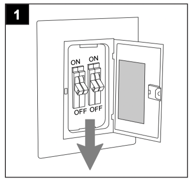
1.Turn off circuit breakers and wall switch to the fan supply line leads.
DANGER: Failure to disconnect power supply prior to installation may result in serious injury or death.
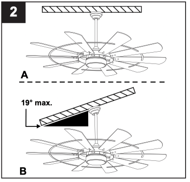
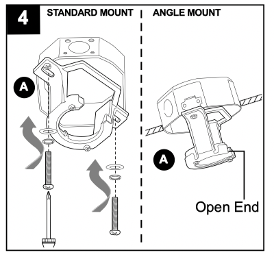
2. Determine mounting method to use.
A. Standard mount
B. Angle mount
IMPORTANT: If using the angle mount, ensure the ceiling angle is not steeper than 19°.
NOTE: Closemount option is not available for this fan.
*Helpful Hint: Downrod-style mounting is best suited for ceilings 8 ft. high or higher. For taller ceilings you may want to use a longer downrod (not included). Angle-style mounting is best suited for angled or vaulted ceilings. A longer downrod is sometimes necessary to ensure proper blade clearance.
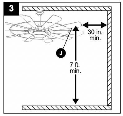
3. Check to make sure blades (J) will be at least 30 inches from any obstruction at least 7 ft. above the floor.
4. Secure mounting bracket (A) to outlet box (not included) using screws, spring washers and flat washers provided with the outlet box.
*NOTE: It is very important you use the proper hardware when installing the mounting bracket (A) as this will support the fan.
IMPORTANT: If using the angle mount, make sure open end of mounting bracket (A) is installed facing the higher point of the ceiling, and ensure the ceiling angle is not steeper than 19°.
5a. Remove pin (D) and clip (E) from downrod (C).
5b. Partially loosen preassembled set screws and nuts in yoke at top of motor assembly (I).
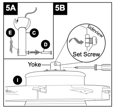
6. Insert downrod (C) through canopy (F), canopy cover (G) and yoke cover (H). NOTE: Canopy cover (G) must be turned with the shiny side toward the motor assembly (I).
Then, thread wires from motor assembly (I) through downrod (C).
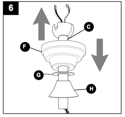
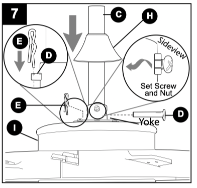
7. Slip downrod (C) into motor assembly yoke, align holes and re-install pin (D) and clip (E). Tighten set screws in motor assembly yoke and then tighten preassembled nuts on the set screws. Then, slide yoke cover (H) down until it rests on top of motor assembly (I).
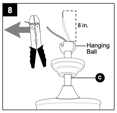
8. Depending on the length of downrod you use, you may need to cut the lead wires back to simplify the wiring. If you decide to cut back the lead wires, it is suggested you do so in the following manner:
Take the lead wires and make sure you have pulled them all the way through the top of the downrod. Start at the TOP of the hanging ball on the downrod and measure 8 in. of lead wire, then cut the excess wire off with wire cutters (not included).
NOTE: If you do not cut back the lead wires, Step 9 is not necessary and you may proceed to Step 10 instead.
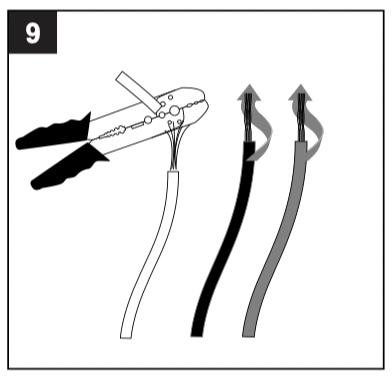
9. If you decided to cut back the lead wires in Step 8, strip 1/2 in. of insulation from end of each wire -- WHITE, BLACK, AND GREEN (if applicable). Twist stripped ends of each strand of wire within the insulation with pliers (not included).
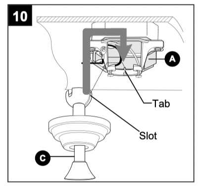
10. Install hanging ball of downrod (C) into opening of mounting bracket (A). Align one of the slots in hanging ball with tab in mounting bracket (A).
DANGER: Failure to align one of the slots in the ball with the tab may result in serious injury or death.
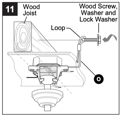
11. Find a secure attachment point (wood ceiling joist recommended) and secure safety cable (O). Use a heavy-duty wood screw, washer and lock washer (all not included) to secure safety cable (O) loop. If the safety cable (O) slips, the loop must be adjusted tighter.
NOTE: Extra cable slack can be left in ceiling area.
WIRING
WARNING: To reduce the risk of fire, electrical shock or personal injury, wire connectors provided with this fan are designed to accept only one 12-gauge house wire and two lead wires from the fan. If your house wire is larger than 12-gauge or there is more than one house wire to connect to the corresponding fan lead wires, consult an electrician for the proper size wire connectors to use.
CAUTION: Be sure outlet box is properly grounded and that a ground (green or bare) wire is present.
WARNING: If house wires are different colors than referred to in the following steps, stop immediately. A professional electrician is recommended to determine wiring.
WARNING: Using a full range dimmer switch (not included) to control fan speed will cause a loud humming noise from fan. To reduce the risk of fire or electrical shock, do NOT use a full range dimmer switch to control fan speed.
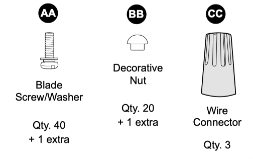
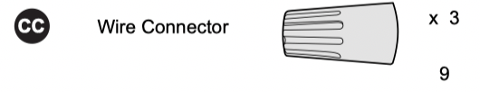
1. IMPORTANT: For each wire connection below, use one of the wire connectors (CC), making sure to screw wire connector (CC) on in a clockwise direction.]
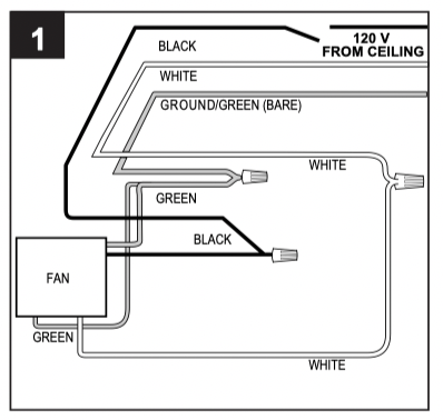
Connect BLACK wire from fan to BLACK wire from ceiling. Connect WHITE wire from fan to WHITE wire from ceiling. Connect all GROUND (GREEN) wires together from fan (on mounting bracket) to BARE/GREEN wire from ceiling.
NOTE: BLACK wire is hot power for fan. WHITE wire is common for fan and light kit. BARE/GREEN wire is ground.
Hardware Used
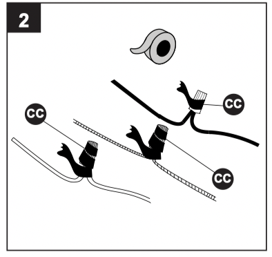
2. Wrap electrical tape (not included) around each individual wire connector (CC) down to the wire.
WARNING: Make sure no bare wire or wire strands are visible after making connections. Place GREEN and WHITE connections on opposite side of the outlet box from the BLACK and BLUE (if applicable) connections.
FINAL INSTALLATION
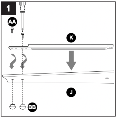
1. DANGER: To reduce the risk of serious bodily injury, DO NOT use power tools to assemble the blades (J). If overtightened, blades (J) may crack and break.
Select five blades (J) to attach the five blade brackets (K). Place one blade bracket (K) on top of blade (J) aligning the two biggest of four holes at top of blade (J). Attach blade bracket (K) to top of blade (J) with two blade screws/washers (AA), and two decorative nuts (BB).
Repeat step for the other four blades (J).
Hardware Used

Hardware Used

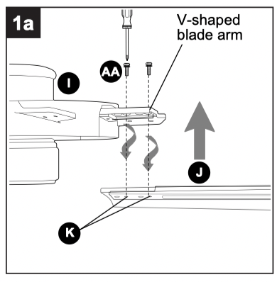
1a. Align the two smallest of four holes of blade bracket (K) with the two holes on one of the V-shaped blade arms on the edge of motor assembly (I).
Attach blade (J) to blade arm with two blade screws/washers (AA) only.
Repeat step for the other four blades (J).
Hardware Used

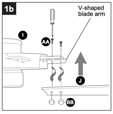
1b. Attach one of the remaining five blades (J) to the V-shaped blade arms on the motor assembly (I) using two blade screws/washers (AA) and two decorative nuts (BB).
Repeat step for the other four remaining blades (J).
Hardware Used

Hardware Used

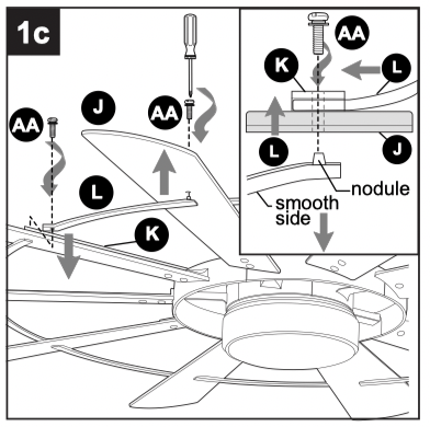
1c. Connect each blade (J) using the blade bars (L).
On the topside of the blade (J), slide the bent portion of the blade bar (L) directly under the opening at the end of the blade bracket (K), aligning the holes. Then, on the underside of the blade (J), insert the nodule portion of another blade bar (L) directly under the same hole. Secure with one blade screw/washer (AA).
NOTE: Blade bar (L) must be turned with the smooth side toward the floor.
Repeat step for the remaining blade bars (L) until the blades (J) are all connected.
CAUTION: Assistance from another person is recommended for this step.
Hardware Used

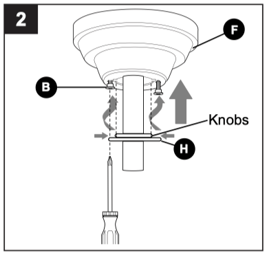
2. Locate two canopy mounting screws (B) on underside of mounting bracket (A) and remove canopy mounting screw (B) closest to the open end of the mounting bracket (A). Partially loosen the other canopy mounting screw (B). Lift canopy (F) to mounting bracket (A). Place rounded part of slotted hole in canopy (F) over loosened canopy mounting screw (B) and push up. Twist canopy (F) to lock. Re-insert canopy mounting screw (B) that was removed, then tighten both canopy mounting screws (B).
Use arrows on inside of canopy cover (G) to locate knobs on center ring of canopy cover (G). Slide canopy cover (G) up to canopy (F), aligning knobs on canopy cover (G) with openings in bottom of canopy (F). Press up gently but firmly on canopy cover (G) until you hear it snap onto the bottom of the canopy (F) and then turn canopy cover (G) clockwise about 1/2 in.
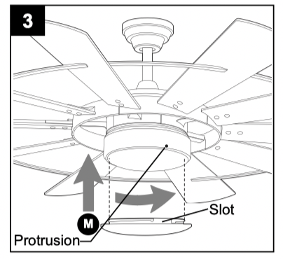
3. Align slots on shade (M) with protrusions on underside of motor assembly (I). Turn shade (M) clockwise until it no longer turns.
NOTE: Pull down gently on the shade (M) to make sure it is secured completely.
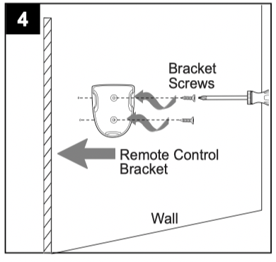
4. If you wish to use the remote control bracket from remote pack (N) on a wood surface, install bracket screws from remote pack (N) through bracket and into the desired installation site.
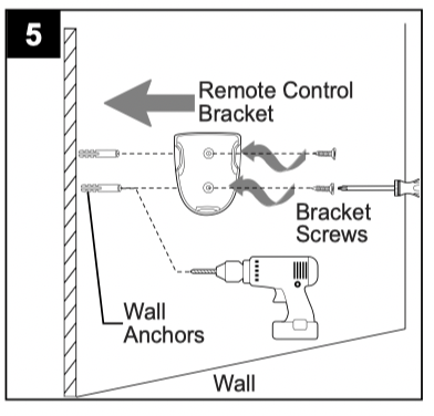
5. If mounting surface is drywall, mark the location of the holes using a pencil or a marker (not included). Use a 7/32 in. drill bit (not included) to drill two pilot holes in drywall at marked locations.
Position plastic anchor in each pilot hole. Gently tap plastic anchors with a hammer (not included) until flush with wall surface. Screw bracket screws into plastic anchor.
The remote control transmitter from remote pack (N) rests inside the bracket.
OPERATING INSTRUCTIONS
CAUTION: The remote control transmitter can be programmed to multiple receivers or fans. If this is not desired, turn wall switch off to any other programmable receiver or fan.
FCC Compliance Notice for Remote Control and LED Light Kit Modifications not approved by the party responsible for compliance could void the user's authority to operate the equipment.
This device complies with Part 15 of the FCC Rules. Operation is subject to the following two conditions: (1) this device may not cause harmful interference, (2) this device must accept any interference received, including interference that may cause undesired operation.
*NOTE: This equipment has been tested and found to comply with the limits for a Class B digital device, pursuant to Part 15 of the FCC Rules. These limits are designed to provide reasonable protection against harmful interference in a residential installation. This equipment generates, uses and can radiate radio frequency energy and, if not installed and used in accordance with the instructions, may cause harmful interference to radio communications. However, there is no guarantee that interference will not occur in a particular installation. If this equipment does cause harmful interference to radio or television reception, which can be determined by turning the equipment off and on, the user is encouraged to try to correct the interference by one or more of the following measures:
* Reorient or relocate the receiving antenna.
* Increase the separation between the equipment and receiver.
* Connect the equipment into an outlet on a circuit different from that to which the receiver is connected.
* Consult the dealer or an experienced radio/TV technician for help.
Distributed by: Litex Industries Inc., P.O. Box 535639, Grand Prairie, TX, 75053; 1-800-527-1292
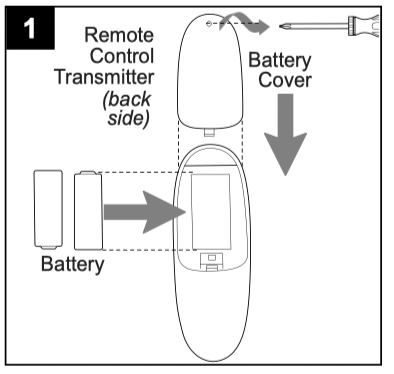
1. Remove screw on the back of remote control transmitter in remote pack (N) to remove battery cover. Install two AAA batteries (included).
Replace battery cover on remote control transmitter with screw just removed.
WARNING: Choking Hazard - Small parts. Keep battery away from children.
NOTE: Battery is NOT rechargeable. Remove battery with low or no charge and dispose of properly.
CAUTION: “DO NOT DISPOSE OF BATTERIES IN FIRE, BATTERIES MAY EXPLODE OR LEAK.” - When disposing of household alkaline batteries, it is best to check with your local and state recycling or household hazardous waste coordinators concerning the specifics of the program in your area. You may also locate a recycling center by calling 1-800-8-BATTERY or 1-877-2-RECYCLE or visit epa/epawaste/index or earth911 for more information.
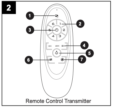
2. Operation buttons on the panel of the remote control transmitter:
1 - Reverse function for winter & summer
2 - Fan speeds: 1 (lowest) to 6 (highest)
3 - To turn fan ON or OFF
4 - Timer: Fan stops after 1h/4h/8h
5 - To turn light ON or OFF
6 - Breeze: fan speeds automatic cycle between 1 to 6 speeds.
7 - Vacation mode: switch on the light kit 5 minutes each 2 hours.
Tap  button quickly to turn lights off or on. Hold button down to increase or decrease lights. If you press button in excess of 0.7 seconds, it becomes a dimmer. The lights vary cyclically in 8 seconds. The light button has an auto resume function, which keeps the light at the same brightness as the last time it was turned off.
CARE AND MAINTENANCE
At least twice each year, lower canopy (F) to check downrod (C) assembly, and then tighten all screws on fan. Clean motor assembly (I) with only a soft brush or lint-free cloth to avoid scratching the finish. Clean blades (J) with a lint-free cloth. You may occasionally apply a light coat of furniture polish to wood blades for added protection.
IMPORTANT: Shut off main power supply before beginning any maintenance. Do not use water or a damp cloth to clean the ceiling fan.
Total wattage for this fan is 18 watts; do not attempt to replace the LEDs.
TROUBLESHOOTING
WARNING: Before beginning work, shut off the power supply to avoid electrical shock.
|
PROBLEM
|
POSSIBLE CAUSE |
CORRECTIVE ACTION |
|
Fan does not move.
|
1. Reverse switch not engaged.
2. Power is off or fuse is blown.
3. Faulty wire connection.
4. Blades are not installed.
|
1. Push switch firmly either left or right.
2. Turn power on or check fuse.
3. Turn power off. Loosen canopy and check all connections.
4. Attach blades to fan.
|
|
Noisy operation.
|
1. Blades are loose.
2. Cracked blade.
3. Full range dimmer switch.
4. Fan is new.
|
1. Tighten all blade screws.
2. Replace blade.
3. Replace with an approved speed control device.
4. Allow fan a “break in” period of a few days, especially when running the fan at Medium and High speeds.
|
|
Excessive wobbling.
|
1. Blades are loose.
2. Unbalanced blades.
3. Fan not securely mounted.
4. Fan too close to vaulted ceiling.
5. Set screw(s) on motor assembly yoke is (are) not tightened properly.
|
1. Tighten all blade screws/washers.
2. Switch one blade with a blade from the opposite side.
3. Turn power off. Carefully loosen canopy and verify that mounting bracket is secure.
4. Use a longer downrod or move fan to another location.
5. Tighten yoke set screw(s) securely.
|
|
Fan operates but light fails.
|
1. Wires in canopy not wired properly.
2. Wall switch to fan is off.
|
1. Check wires in canopy and, if necessary, re-wire according to instructions on page 9.
2. Make sure that wall switch to fan is on.
|
NOTE: A small amount of "wobble" is normal and should not be considered a defect.