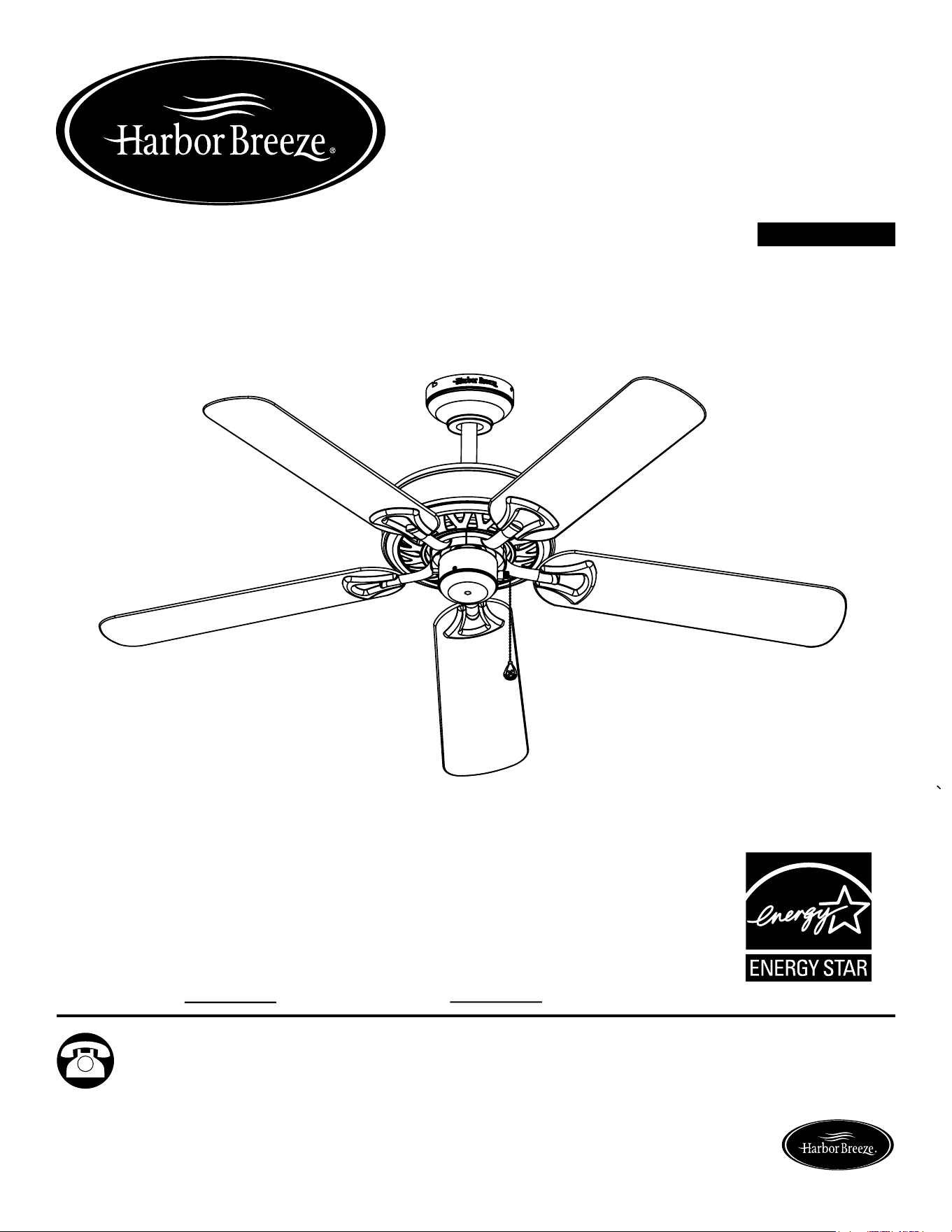
115
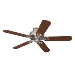
CALERA CEILING FAN
ITEM #0036261
ARTÍCULO #0036261
MODEL #00829
MODELO #00829
Español p. 15
Serial Number
Purchase Date
Harbor Breeze ® is a registered trademark of LF,
LLC. All Rights Reserved.
Questions, problems, missing parts? Before returning to your retailer, call our customer
service department at 1-800-643-0067, 8 a.m. - 6 p.m., EST, Monday - Thursday, 8 a.m. -
5 p.m., EST, Friday.
ATTACH YOUR RECEIPT HERE
Lowes.com/harborbreezeLowes.com/harborbreeze
UL MODEL #CLRO52-II
MODELO UL #CLRO52-II
Harbor Breeze ® es una marca registrada de LF,
LLC. Todos los derechos reservados.
VENTILADOR DE TECHO
CALERA
¿Preguntas, problemas, piezas faltantes? Antes de volver a la tienda, llame a nuestro
Departamento de Servicio al Cliente al 1-800-643-0067, de lunes a jueves de 8 a.m. a 6 p.m.,
hora estándar del Este, o los viernes de 8 a.m. a 5 p.m., hora estándar del Este.
ADJUNTE SU RECIBO AQUÍ
Número de serie
Fecha de compra
EB 14201

32
TABLE OF CONTENTS
Safety Information............................................................................................................... 3
Package Contents............................................................................................................... 4
Hardware Contents............................................................................................................. 5
Preparation.......................................................................................................................... 5
Initial Installation.................................................................................................................. 6
Downrod Style Fan Mounting.............................................................................................. 7
Closemount Style Fan Mounting......................................................................................... 8
Wiring ..................................................................................................................................... 10
Final Installation.................................................................................................................. 10
Operating Instructions.......................................................................................................... 13
Care and Maintenance........................................................................................................ 13
Troubleshooting................................................................................................................... 13
Warranty.............................................................................................................................. 14
Replacement Parts List ...................................................................................................... 14
Lowes.com/harborbreeze
SAFETY INFORMATION
READ AND SAVE THESE INSTRUCTIONS
Please read and understand this entire manual before attempting to assemble, operate or install the
product.
• When using an existing outlet box, be sure the box is securely attached to the building structure and
can support the full weight fo the fan, so as to avoid potential serious injury or death.
• All wiring must be in accordance with the National Electrical Code “ANSI/NFPA 70-1999” and
local electrical codes. Electrical installation should be performed by a qualied licensed electrician.
• Electrical diagrams are for reference only.
• Suitable for use in wet locations when installed in a GFCI protected branch circuit.
• The net weight of this fan is: 17.16 lbs.
WARNING
CAUTION
WARNING
WARNING
WARNING
Lowes.com/harborbreeze
FIRE, ELECTRIC SHOCK OR PERSONAL INJURY HAZARD
To reduce the risk of re, electric shock, or personal injury, mount to outlet box marked
“ACCEPTABLE FOR FAN SUPPORT OF 15.9 KG OR LESS” and use mounting screws
provided with the outlet box. Most outlet boxes commonly used for the support of lighting
xtures are not acceptable for fan support and may need to be replaced. Consult a
qualied electrician if in doubt.
ELECTRIC SHOCK HAZARD
To reduce the risk of electric shock, do not use this fan with any solid-state speed
control device.
ELECTRIC SHOCK HAZARD
To reduce the risk of electric
shock, make sure electricity has
been turned off at the circuit
breaker or fuse box before
beginning installation.
PERSONAL INJURY HAZARD
To reduce the risk of injury to persons, install
fan so that the blade is at least 7 ft. above the
oor.
PERSONAL INJURY HAZARD
Reduce the risk of personal injury, do not bend the blade brackets when installing the
brackets, balancing the blades, or cleaning the fan. Do not insert foreign objects in
between rotating fan blades.
54
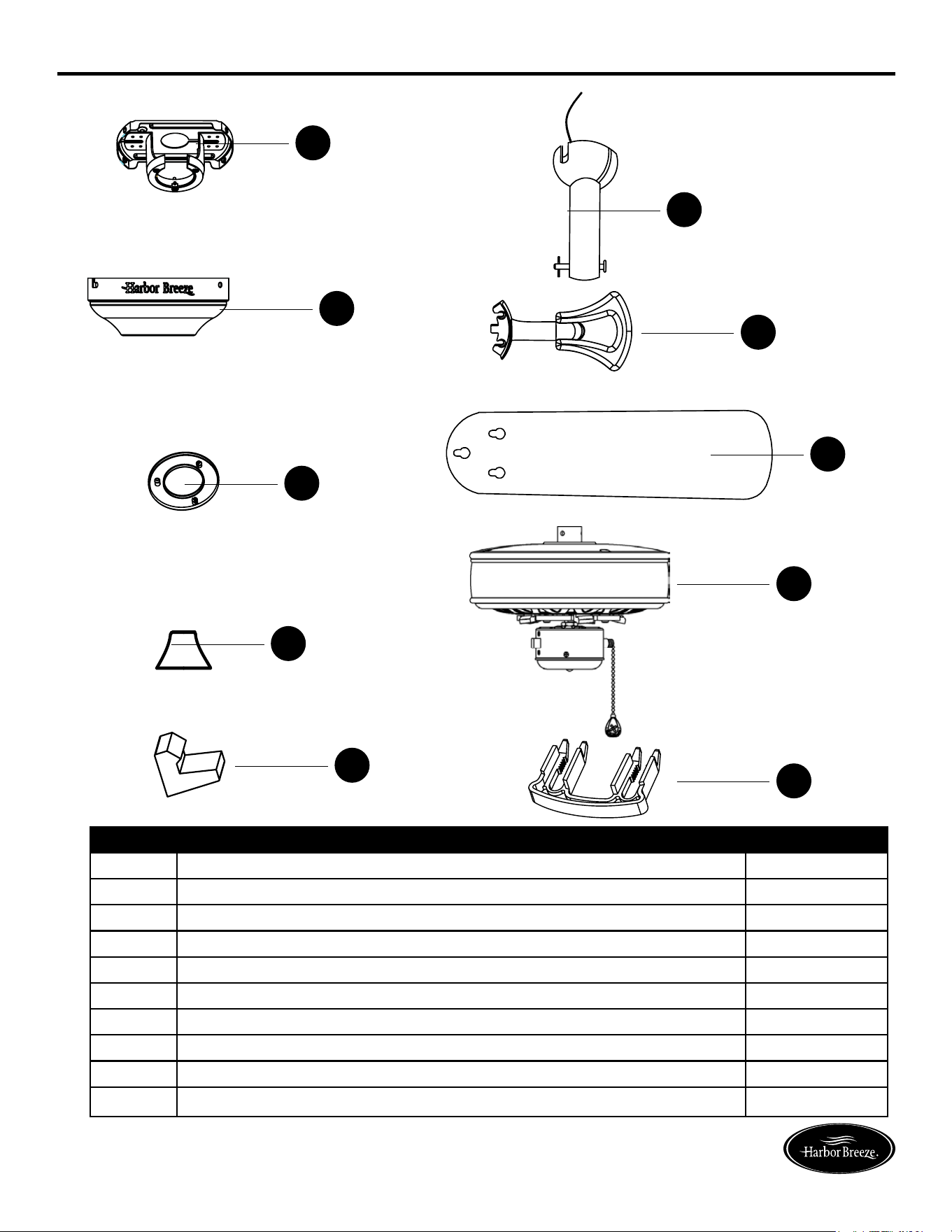
PACKAGE CONTENTS
PREPARATION
Lowes.com/harborbreeze Lowes.com/harborbreeze
PART DESCRIPTION QUANTITY
A Mounting Bracket (preassembled to canopy (B)) 1
B Canopy 1
C Canopy Cover (preassembled to canopy (B)) 1
D Yoke Cover 1
E Downrod 1
F Blade Bracket 5
G Blade 5
H Motor Housing Assembly 1
I
Rubber Piece (preassembled to motor housing assembly (H))
5
J Plastic Block (preassembled to motor housing assembly (H)) 5
A
B
C
D
H
G
F
E
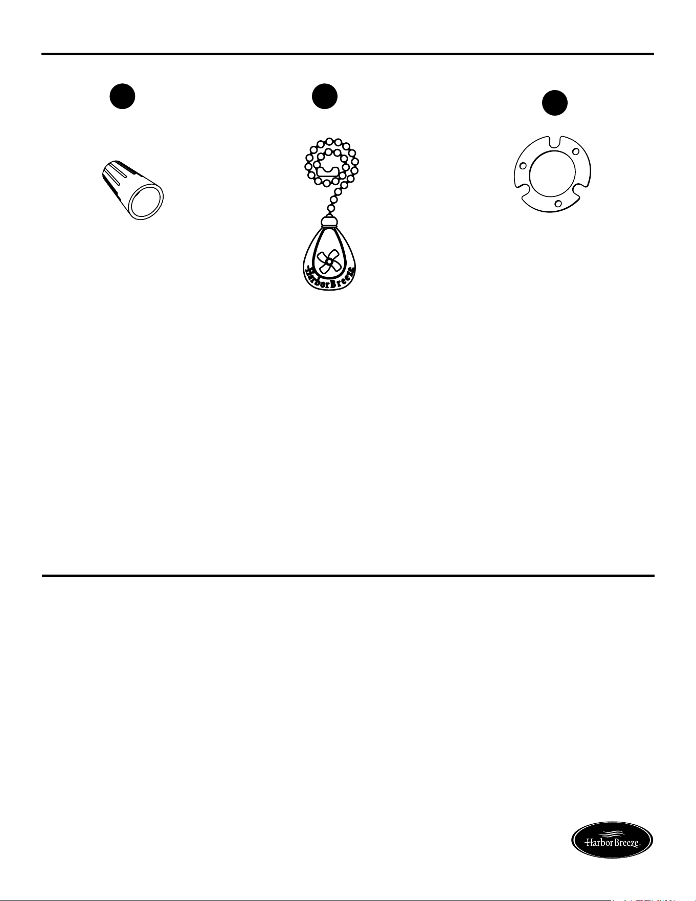
HARDWARE CONTENTS (shown actual size)
BB
CC
AA
Wire Connector
Qty. 4
Fan Pull Chain
Extension
Qty. 1
(NOT TO SCALE)
Rubber Gasket
Qty. 1
(NOT TO SCALE)
I
J
Before beginning assembly of product, make sure all parts are present. Compare parts with package
contents list and hardware contents list. If any part is missing or damaged, do not attempt to
assemble the product.
Estimated Assembly Time: 20 minutes
Tools Required for Assembly (not included): Phillips screwdriver, step ladder, electrical tape, pliers,
wire cutter, wire stripper.
54
PACKAGE CONTENTS
PREPARATION
Lowes.com/harborbreeze Lowes.com/harborbreeze
PART DESCRIPTION QUANTITY
A Mounting Bracket (preassembled to canopy (B)) 1
B Canopy 1
C Canopy Cover (preassembled to canopy (B)) 1
D Yoke Cover 1
E Downrod 1
F Blade Bracket 5
G Blade 5
H Motor Housing Assembly 1
I
Rubber Piece (preassembled to motor housing assembly (H))
5
J Plastic Block (preassembled to motor housing assembly (H)) 5
A
B
C
D
H
G
F
E
HARDWARE CONTENTS (shown actual size)
BB
CC
AA
Wire Connector
Qty. 4
Fan Pull Chain
Extension
Qty. 1
(NOT TO SCALE)
Rubber Gasket
Qty. 1
(NOT TO SCALE)
I
J
Before beginning assembly of product, make sure all parts are present. Compare parts with package
contents list and hardware contents list. If any part is missing or damaged, do not attempt to
assemble the product.
Estimated Assembly Time: 20 minutes
Tools Required for Assembly (not included): Phillips screwdriver, step ladder, electrical tape, pliers,
wire cutter, wire stripper.
6 7
INITIAL INSTALLATION INITIAL INSTALLATION
DOWNROD STYLE FAN MOUNTING
1
4
2
1
3
2
Lowes.com/harborbreeze Lowes.com/harborbreeze
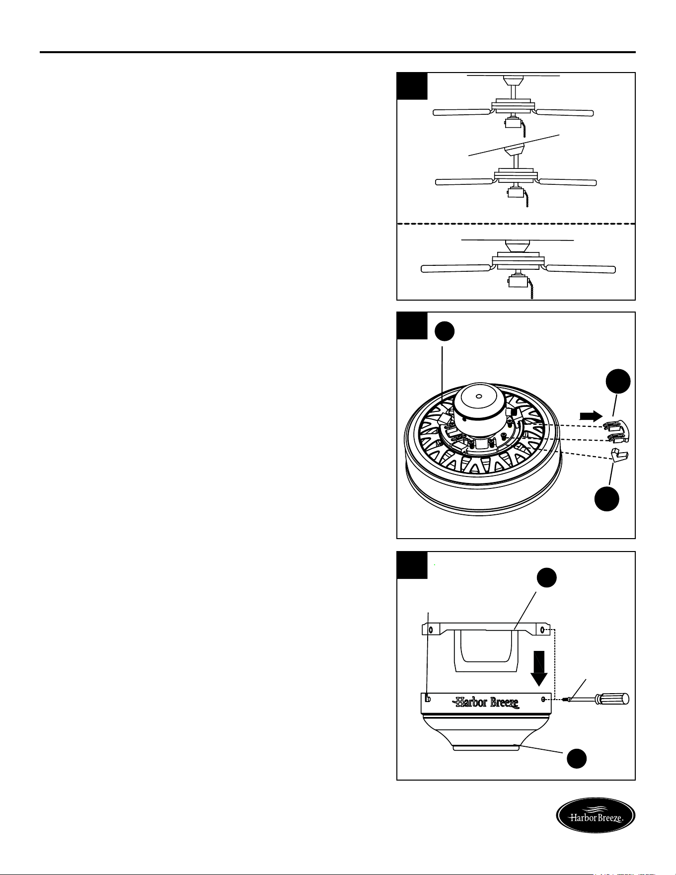
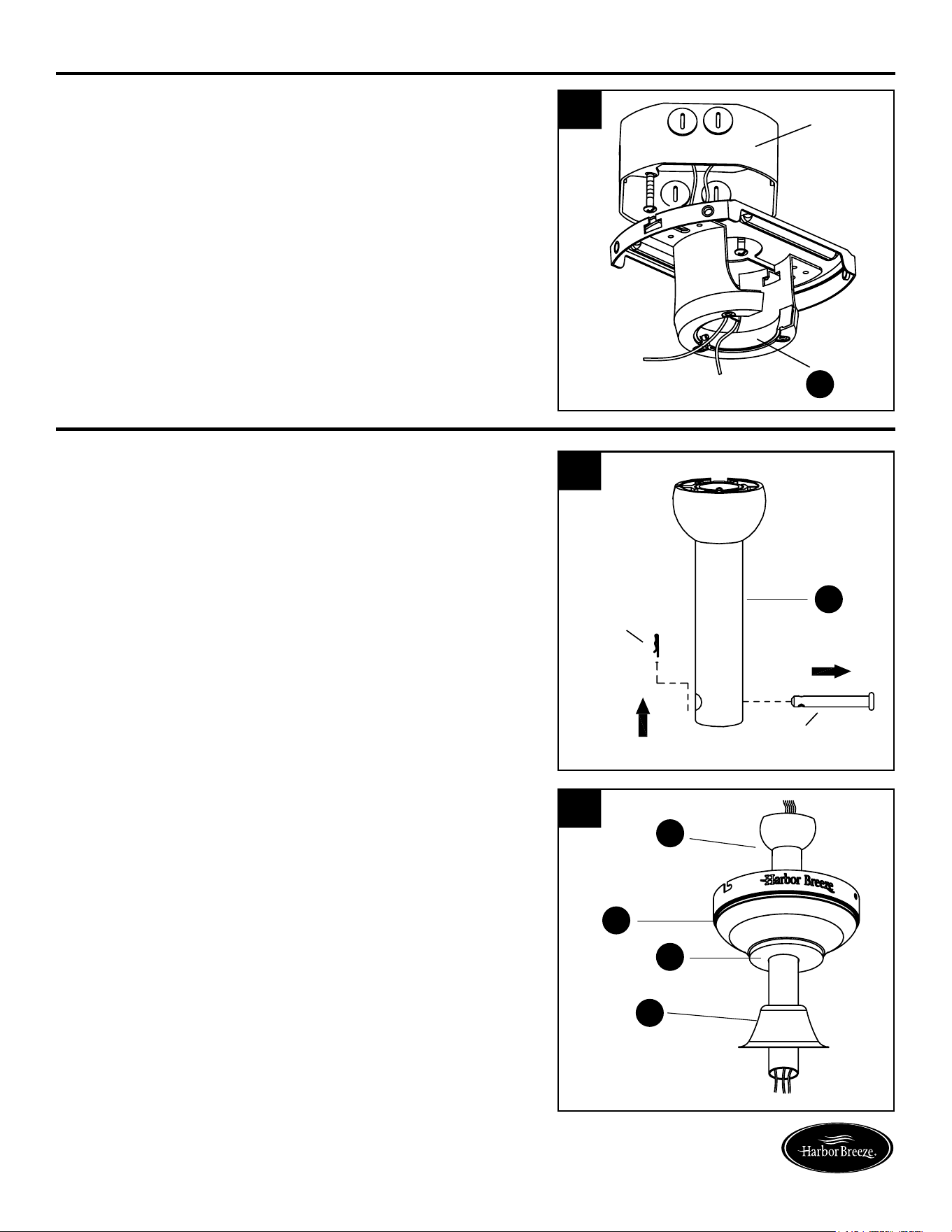
1. Determine mounting method to use.
A - Downrod Mount (normal or angled ceiling)
B - Closemount (normal ceiling only)
Important: lf using the angle mount, check
to make sure the ceiling angle is not steeper than 20°.
3. Remove the mounting bracket (A) from the canopy (B)
by loosening the four screws on the top of the canopy
(B). Remove the two non-slotted screws and save, then
loosen the slotted screws. This will enable you to remove
the mounting bracket (A).
4. Install the mounting bracket (A) to the outlet
box (not included), sliding the mounting bracket (A) over
the two outlet box screws (not included). Securely tighten
the two outlet box screws.
IMPORTANT: If using the angle mount, make sure
open end of mounting bracket (A) is installed facing the
ceiling.
Follow mounting instructions for “Downrod Style
Fan Mounting” or “Closemount Style Fan
Mounting” depending on mounting method (A or
B) chosen in Step 1 on previous page.
1. Remove pin and clip from downrod (E).
2. Insert downrod (E) through canopy (B), canopy
cover (C) and yoke cover (D). Thread wires from the
motor housing assembly (H) through downrod (E).
A
B
H
B
A
Remove
and save
Loosen but
Do not remove
A
outlet box
E
clip
pin
E
B
C
D
I
J
Remove and discard the five rubber pieces (I) and
five plastic blocks (J) from the underside of the motor
housing assembly (H).
2
.
6 7
INITIAL INSTALLATION INITIAL INSTALLATION
DOWNROD STYLE FAN MOUNTING
1
4
2
1
3
2
Lowes.com/harborbreeze Lowes.com/harborbreeze
1. Determine mounting method to use.
A - Downrod Mount (normal or angled ceiling)
B - Closemount (normal ceiling only)
Important: lf using the angle mount, check
to make sure the ceiling angle is not steeper than 20°.
3. Remove the mounting bracket (A) from the canopy (B)
by loosening the four screws on the top of the canopy
(B). Remove the two non-slotted screws and save, then
loosen the slotted screws. This will enable you to remove
the mounting bracket (A).
4. Install the mounting bracket (A) to the outlet
box (not included), sliding the mounting bracket (A) over
the two outlet box screws (not included). Securely tighten
the two outlet box screws.
IMPORTANT: If using the angle mount, make sure
open end of mounting bracket (A) is installed facing the
ceiling.
Follow mounting instructions for “Downrod Style
Fan Mounting” or “Closemount Style Fan
Mounting” depending on mounting method (A or
B) chosen in Step 1 on previous page.
1. Remove pin and clip from downrod (E).
2. Insert downrod (E) through canopy (B), canopy
cover (C) and yoke cover (D). Thread wires from the
motor housing assembly (H) through downrod (E).
A
B
H
B
A
Remove
and save
Loosen but
Do not remove
A
outlet box
E
clip
pin
E
B
C
D
I
J
Remove and discard the five rubber pieces (I) and
five plastic blocks (J) from the underside of the motor
housing assembly (H).
2
.
9
DOWNROD STYLE FAN MOUNTING
CLOSEMOUNT STYLE FAN MOUNTING
CLOSEMOUNT STYLE FAN MOUNTING
3 2
3
4
Lowes.com/harborbreeze
Lowes.com/harborbreeze
Lowes.com/harborbreeze
Lowes.com/harborbreeze
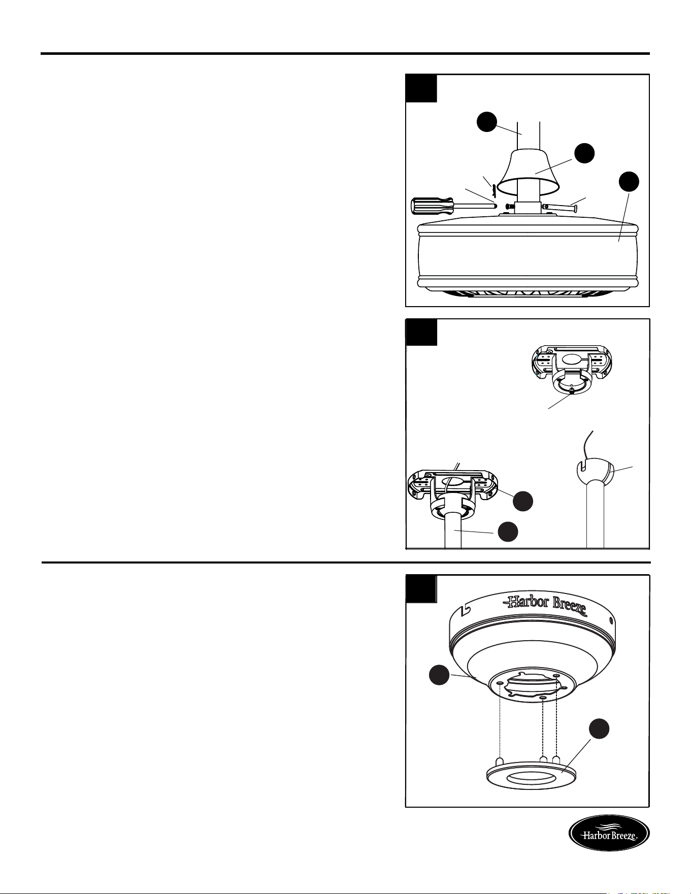
3. Loosen the two set screws from the yoke. Slip
downrod (E) into yoke, aligning holes in downrod (E)
and yoke. Insert the pin through yoke and downrod (E).
Insert clip into pin until it snaps into place. Tighten set
screws. Slide the yoke cover (D) down over the motor
housing assembly (H).
4. lnstall hanger ball on the top of downrod (E) into
mounting bracket (A) opening. Rotate fan until slot on
hanger ball engages the tab on the mounting bracket
(A).
Warning: Be careful when aligning the tab to the slot!
If not fully engaged, there is a possibility of fan falling,
which may result in serious injury or death.
You may now proceed to the WIRING section on
page 10.
2. Remove every other screw from the top of motor
housing assembly (H) and save.
3. Place the rubber gasket (CC) over the remaining
screws. Pull wires through hole in canopy (B) and
attach canopy (B) to motor housing (H). Align the
mounting holes with the holes in the motor and fasten
using the three screws removed in previous step.
Tighten the screws securely.
4. Hang the fan on the hook on the mounting bracket (A)
using one of the non-slotted holes in the canopy (B).
1. Remove the canopy cover (C) from the bottom of the
canopy (B).
clip
pin
set screw
E
D
H
H
H
B
Hardware Used
x 1
Rubber gasket
B
A
hook
CC
CC
tab
slot
A
E
4
4
B
C
B
C
1
1
8

9
DOWNROD STYLE FAN MOUNTING
CLOSEMOUNT STYLE FAN MOUNTING
CLOSEMOUNT STYLE FAN MOUNTING
3 2
3
4
Lowes.com/harborbreeze
Lowes.com/harborbreeze
Lowes.com/harborbreeze
Lowes.com/harborbreeze
3. Loosen the two set screws from the yoke. Slip
downrod (E) into yoke, aligning holes in downrod (E)
and yoke. Insert the pin through yoke and downrod (E).
Insert clip into pin until it snaps into place. Tighten set
screws. Slide the yoke cover (D) down over the motor
housing assembly (H).
4. lnstall hanger ball on the top of downrod (E) into
mounting bracket (A) opening. Rotate fan until slot on
hanger ball engages the tab on the mounting bracket
(A).
Warning: Be careful when aligning the tab to the slot!
If not fully engaged, there is a possibility of fan falling,
which may result in serious injury or death.
You may now proceed to the WIRING section on
page 10.
2. Remove every other screw from the top of motor
housing assembly (H) and save.
3. Place the rubber gasket (CC) over the remaining
screws. Pull wires through hole in canopy (B) and
attach canopy (B) to motor housing (H). Align the
mounting holes with the holes in the motor and fasten
using the three screws removed in previous step.
Tighten the screws securely.
4. Hang the fan on the hook on the mounting bracket (A)
using one of the non-slotted holes in the canopy (B).
1. Remove the canopy cover (C) from the bottom of the
canopy (B).
clip
pin
set screw
E
D
H
H
H
B
Hardware Used
x 1
Rubber gasket
B
A
hook
CC
CC
tab
slot
A
E
4
4
B
C
B
C
1
1
8
1110
WIRING
FINAL INSTALLATION
FINAL INSTALLATION
2
1
Lowes.com/harborbreezeLowes.com/harborbreeze
2
3
4
Lowes.com/harborbreezeLowes.com/harborbreeze
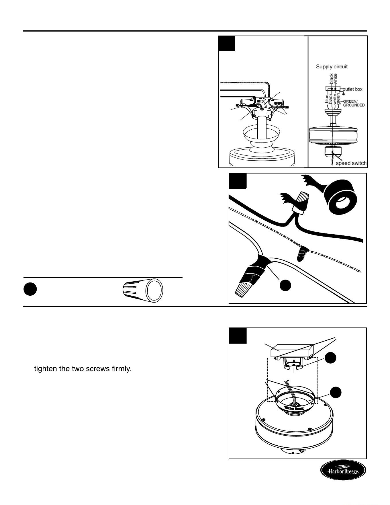
1. Connect the BLACK and BLUE wires from fan to the
house BLACK wire. Connect the WHITE wire from
fan to the house WHITE wire. Connect all
GROUNDED (GREEN) wires together from fan to the
house GREEN/GROUNDED wire.
Note: Black wire is hot power for fan. Blue wire is hot
power for light kit in case of future light kit installation.
White wire is common for fan and light kit. Green wire
is grounded wire. lf house wires are different colors
than referred to above, stop immediately. It is
recommended a professional electrician to determine
proper wiring.
2. To connect wires, twist wire ends together and screw
wire with wire connectors (AA) on in a clockwise
direction. Tape the wire connectors (AA) and wires
together. The wires should be spread apart with the
grounded conductor and the equipment-grounding
conductor on one side of the outlet box and the
ungrounded conductor on the other side of the outlet
box. Be sure no bare wire or wire strands are visible
after making connection. Place green and white
connections on opposite side of box from the black
and blue connections. The splices should be turned
upward and pushed carefully up into the outlet box.
If you installed the fan with “Closemount Style Fan Mounting”, continue to Steps 1 and 2. If
you installed the fan with “Downrod Style Fan Mounting”, skip to Step 3.
1. Remove the fan from the hook on the mounting bracket
(A). Align the locking slots of the canopy (B) with the two
screws in the mounting bracket (A). Push up to engage
the slots and turn clockwise to lock in place. Immediately
2. Install the two screws that were removed in previous step
and tighten securely.
You may now proceed to the Step 4.
3. Directly align the locking slots of the canopy (B) with the
two screws in the mounting bracket (A). Push up to
engage the slots and turn clockwise to lock in place.
screws that were removed in previous step and tighten
securely.
4. Slide the blade bracket (F) to the screw with washer on
the bottom of the fan motor assembly (H) and tightening
the blade bracket screws with washers. Please note that
the blade bracket screws with washers are pre-installed
on the bottom of the fan motor assembly (H). Repeat the
step for the remaining blade brackets (F).
1
Grounded/Green
Black
White
Grounded/
Green
Black
Blue
White
k
n
k
AA
Hardware Used
x 4
Wire connector
AA
outlet box
hook
screws
locking
slots
B
A
B
outlet box
screw
B
outlet box
screw
F
H
screw with washer
1110
WIRING
FINAL INSTALLATION
FINAL INSTALLATION
2
1
Lowes.com/harborbreezeLowes.com/harborbreeze
2
3
4
Lowes.com/harborbreezeLowes.com/harborbreeze
1. Connect the BLACK and BLUE wires from fan to the
house BLACK wire. Connect the WHITE wire from
fan to the house WHITE wire. Connect all
GROUNDED (GREEN) wires together from fan to the
house GREEN/GROUNDED wire.
Note: Black wire is hot power for fan. Blue wire is hot
power for light kit in case of future light kit installation.
White wire is common for fan and light kit. Green wire
is grounded wire. lf house wires are different colors
than referred to above, stop immediately. It is
recommended a professional electrician to determine
proper wiring.
2. To connect wires, twist wire ends together and screw
wire with wire connectors (AA) on in a clockwise
direction. Tape the wire connectors (AA) and wires
together. The wires should be spread apart with the
grounded conductor and the equipment-grounding
conductor on one side of the outlet box and the
ungrounded conductor on the other side of the outlet
box. Be sure no bare wire or wire strands are visible
after making connection. Place green and white
connections on opposite side of box from the black
and blue connections. The splices should be turned
upward and pushed carefully up into the outlet box.
If you installed the fan with “Closemount Style Fan Mounting”, continue to Steps 1 and 2. If
you installed the fan with “Downrod Style Fan Mounting”, skip to Step 3.
1. Remove the fan from the hook on the mounting bracket
(A). Align the locking slots of the canopy (B) with the two
screws in the mounting bracket (A). Push up to engage
the slots and turn clockwise to lock in place. Immediately
2. Install the two screws that were removed in previous step
and tighten securely.
You may now proceed to the Step 4.
3. Directly align the locking slots of the canopy (B) with the
two screws in the mounting bracket (A). Push up to
engage the slots and turn clockwise to lock in place.
screws that were removed in previous step and tighten
securely.
4. Slide the blade bracket (F) to the screw with washer on
the bottom of the fan motor assembly (H) and tightening
the blade bracket screws with washers. Please note that
the blade bracket screws with washers are pre-installed
on the bottom of the fan motor assembly (H). Repeat the
step for the remaining blade brackets (F).
1
Grounded/Green
Black
White
Grounded/
Green
Black
Blue
White
k
n
k
AA
Hardware Used
x 4
Wire connector
AA
outlet box
hook
screws
locking
slots
B
A
B
outlet box
screw
B
outlet box
screw
F
H
screw with washer
1312
FINAL INSTALLATION
5
6
7
Lowes.com/harborbreeze
Lowes.com/harborbreeze
Lowes.com/harborbreeze
Lowes.com/harborbreeze
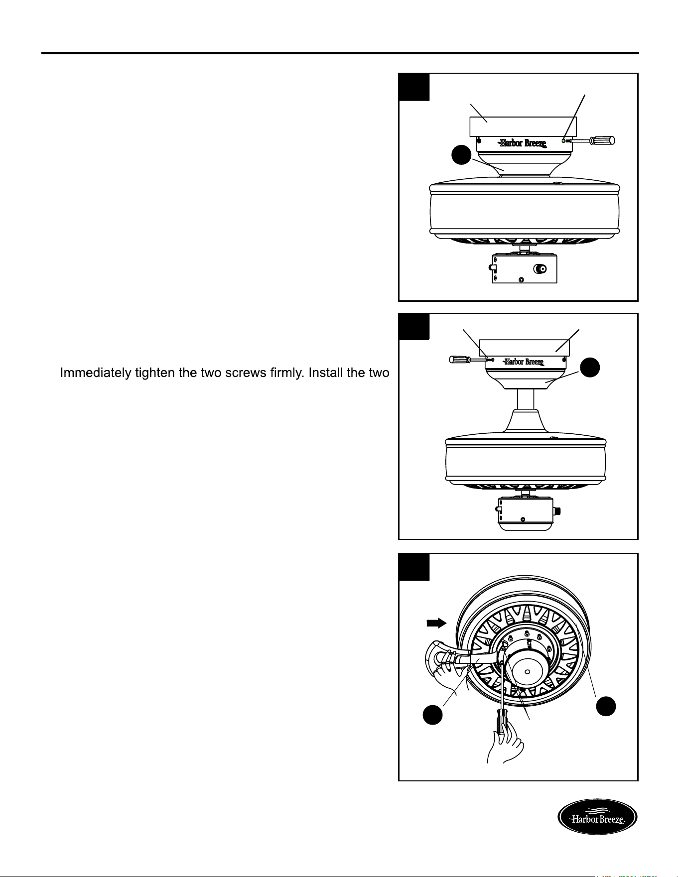
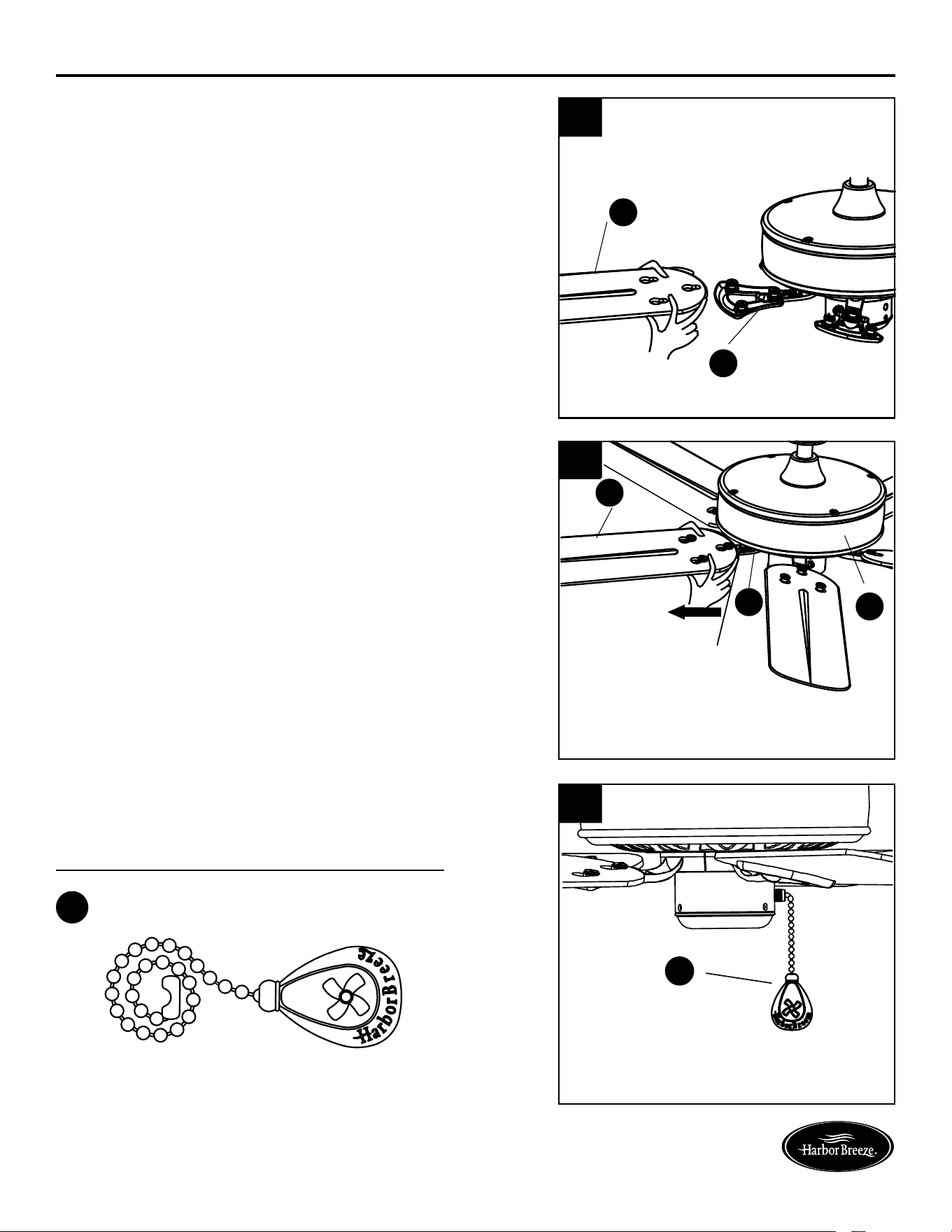
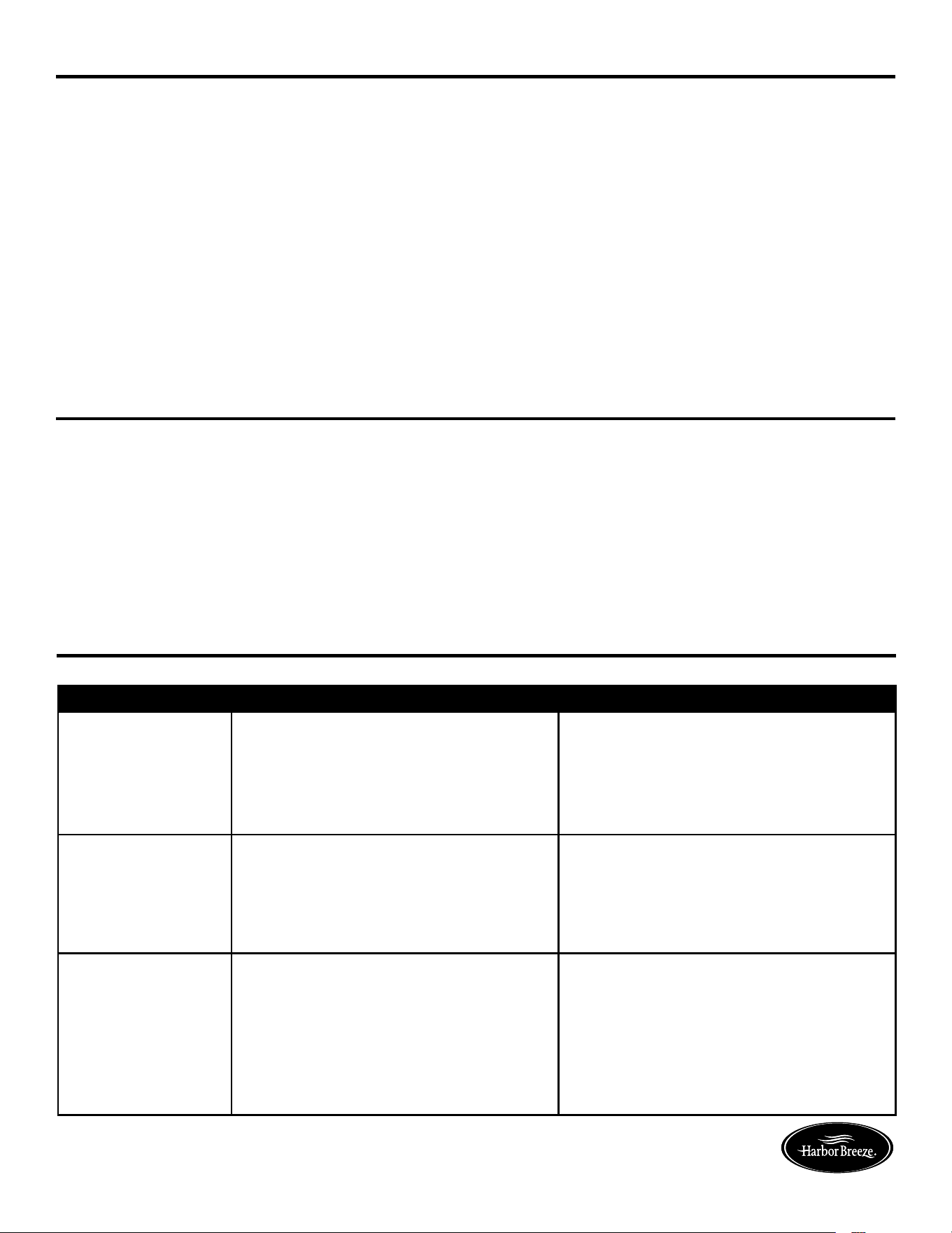
5. Mount the blade (G) to the blade bracket (F) by
aligning the three key-slot holes in the blade (G) with
three posts on the top of the blade bracket (F) and
press the blade (G) down rmly. Ensure the key-slot
holes are properly seated on the blade bracket (F).
6. While still pressing the blade (G) with both hands,
rmly slide the blade (G) away from the motor housing
assembly (H) until the blade (G) engages in the
locking mechanism. Make sure the plastic locking
mechanism at the rear of the blade bracket (F) springs
upward and butts against the edge of the blade (G),
indicating a secure connection.
Note: Visually inspect the top of the blade bracket (F)
to ensure that the locking mechanism is securely in
place. Repeat for the remaining blades (G).
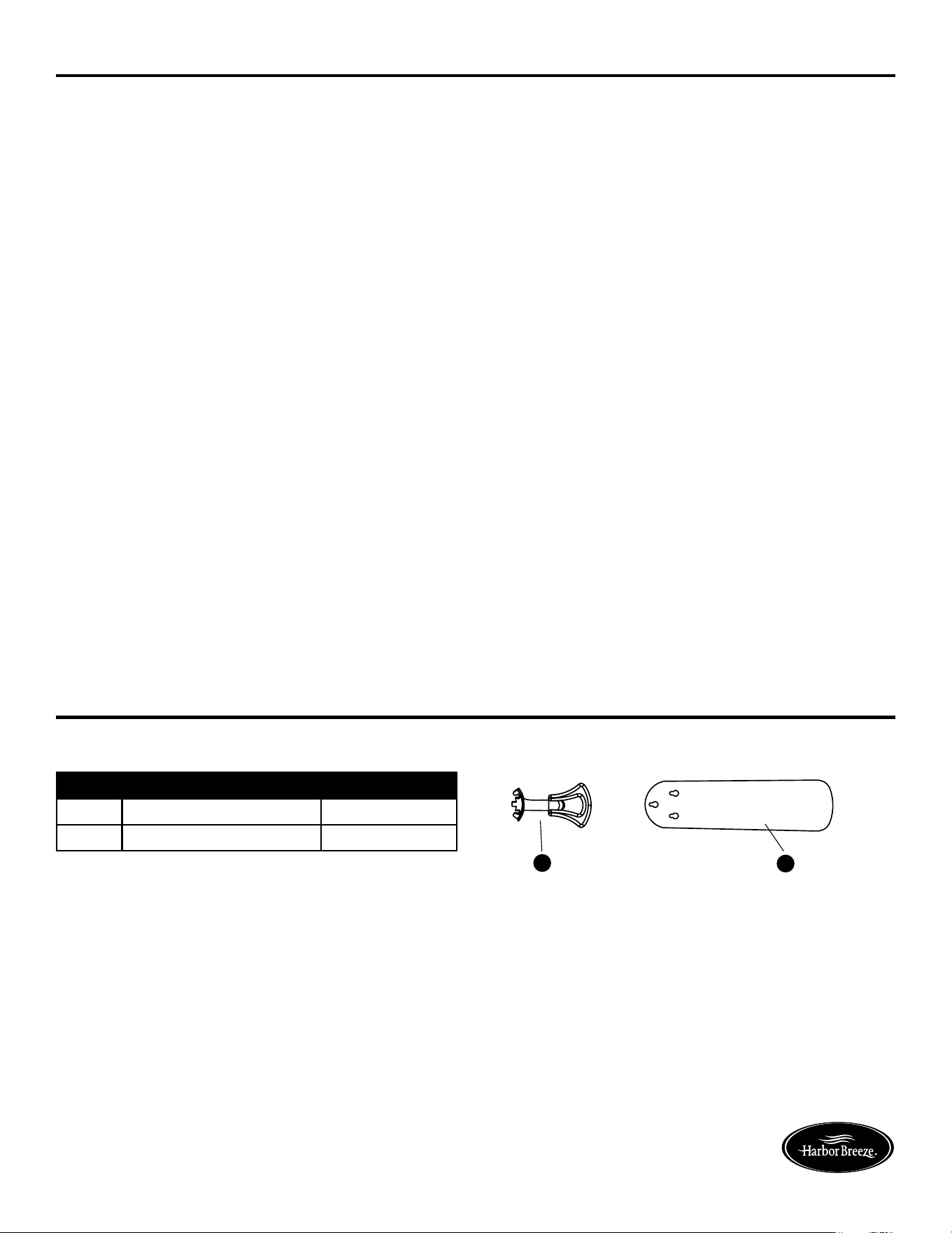
7. Attach the fan pull chain extension (BB).
OPERATING INSTRUCTIONS
PULL CHAIN: The fan pull chain is for motor speed control: High, Medium, Low and Off. Pull the
chain once for each position.
REVERSE SWITCH:
When the season changes, you may want to change to the direction your fan
spins. To switch between clockwise and counterclockwise rotation, ip the fan reversal switch.
Note: Wait for fan to stop before reversing the switch.
A. In cooler weather, clockwise rotation creates an upward air ow, which moves hot air from
the ceiling into the room. Push the switch UP.
B. In warmer weather, counterclockwise rotation creates a downward air ow, which cools the
air. Push the switch DOWN.
• To reduce the risk of re, electric shock or injury to persons, maintain this fan.
• Important: Shut off main power supply before beginning any maintenance.
• Do not use water or detergents when cleaning the fan or fan blades. A dry dust cloth or lightly
dampened cloth will be suitable for most cleaning.
• Clean fan housing with only a soft brush or lint-free cloth to avoid scratching the nish. Clean
blades with a lint-free cloth. You may occasionally apply a light coat of furniture polish to blades for
added protection.
• At least twice each year, tighten all screws and lower canopy to check mounting bracket screws
and downrod assembly.
CARE AND MAINTENANCE
TROUBLESHOOTING
PROBLEM POSSIBLE CAUSE CORRECTIVE ACTION
Excessive wobbling. 1. Blades are loose. 1. Tighten all blade screws.
2. Blade brackets incorrectly attached. 2. Reinstall blade brackets.
3. Unbalanced blades. 3. Switch with blade from opposite side.
4. Fan not securely mounted. 4. Turn power off. Carefully loosen
5. Fan too close to vaulted ceiling. canopy; remount securely.
5. Lower fan or move it to another
location.
Noisy operation. 1. Blades are loose. 1. Tighten all blade screws.
2. Cracked blade. 2. Replace blades (call customer
3. Unapproved speed control. service).
3. Replace with an approved speed
control device.
Fan does not move. 1. Chain switch is “off”. 1. Pull chain switch.
2. Faulty wire connection. 2. Turn power off. Loosen canopy,
3. Reverse switch not engaged. check all connections.
3. Push switch rmly either way.
F
G
plastic locking mechanism
G
H
F
BB
Hardware Used
x 1
Fan pull chain extension
BB
1312
FINAL INSTALLATION
5
6
7
Lowes.com/harborbreeze
Lowes.com/harborbreeze
Lowes.com/harborbreeze
Lowes.com/harborbreeze
5. Mount the blade (G) to the blade bracket (F) by
aligning the three key-slot holes in the blade (G) with
three posts on the top of the blade bracket (F) and
press the blade (G) down rmly. Ensure the key-slot
holes are properly seated on the blade bracket (F).
6. While still pressing the blade (G) with both hands,
rmly slide the blade (G) away from the motor housing
assembly (H) until the blade (G) engages in the
locking mechanism. Make sure the plastic locking
mechanism at the rear of the blade bracket (F) springs
upward and butts against the edge of the blade (G),
indicating a secure connection.
Note: Visually inspect the top of the blade bracket (F)
to ensure that the locking mechanism is securely in
place. Repeat for the remaining blades (G).
7. Attach the fan pull chain extension (BB).
OPERATING INSTRUCTIONS
PULL CHAIN: The fan pull chain is for motor speed control: High, Medium, Low and Off. Pull the
chain once for each position.
REVERSE SWITCH:
When the season changes, you may want to change to the direction your fan
spins. To switch between clockwise and counterclockwise rotation, ip the fan reversal switch.
Note: Wait for fan to stop before reversing the switch.
A. In cooler weather, clockwise rotation creates an upward air ow, which moves hot air from
the ceiling into the room. Push the switch UP.
B. In warmer weather, counterclockwise rotation creates a downward air ow, which cools the
air. Push the switch DOWN.
• To reduce the risk of re, electric shock or injury to persons, maintain this fan.
• Important: Shut off main power supply before beginning any maintenance.
• Do not use water or detergents when cleaning the fan or fan blades. A dry dust cloth or lightly
dampened cloth will be suitable for most cleaning.
• Clean fan housing with only a soft brush or lint-free cloth to avoid scratching the nish. Clean
blades with a lint-free cloth. You may occasionally apply a light coat of furniture polish to blades for
added protection.
• At least twice each year, tighten all screws and lower canopy to check mounting bracket screws
and downrod assembly.
CARE AND MAINTENANCE
TROUBLESHOOTING
PROBLEM POSSIBLE CAUSE CORRECTIVE ACTION
Excessive wobbling. 1. Blades are loose. 1. Tighten all blade screws.
2. Blade brackets incorrectly attached. 2. Reinstall blade brackets.
3. Unbalanced blades. 3. Switch with blade from opposite side.
4. Fan not securely mounted. 4. Turn power off. Carefully loosen
5. Fan too close to vaulted ceiling. canopy; remount securely.
5. Lower fan or move it to another
location.
Noisy operation. 1. Blades are loose. 1. Tighten all blade screws.
2. Cracked blade. 2. Replace blades (call customer
3. Unapproved speed control. service).
3. Replace with an approved speed
control device.
Fan does not move. 1. Chain switch is “off”. 1. Pull chain switch.
2. Faulty wire connection. 2. Turn power off. Loosen canopy,
3. Reverse switch not engaged. check all connections.
3. Push switch rmly either way.
F
G
plastic locking mechanism
G
H
F
BB
Hardware Used
x 1
Fan pull chain extension
BB
14
Lowes.com/harborbreezeLowes.com/harborbreeze
WARRANTY
REPLACEMENT PARTS LIST
For replacement parts, call our customer service department at 1-800-643-0067, 8 a.m. - 6 p.m.,
EST, Monday - Thursday, 8 a.m. - 5 p.m., EST, Friday.
PART DESCRIPTION PART#
F Blade bracket 104000-0294
G Blade 108003-3032
The manufacturer warrants this fan motor to be free from defects in workmanship and material
present at time of shipment from the factory for a period of thirty years after the date of purchase by
the original purchaser. The manufacturer also warrants that all other fan parts, excluding any glass to
be free from defects in workmanship and material at the time of shipment from the factory for a period
of three years after the date of purchase by the original purchaser. The manufacturer agrees to correct
such defect at no charge or at our option replace the ceiling fan with a comparable or superior model.
To obtain warranty service, present a copy of your sales receipt as proof of purchase. All cost of
removal and reinstallation are the expressed responsibility of the purchaser. Any damage to the
ceiling fan by accident, misuse or improper installation, or by affixing accessories not produced by
the manufacturer of the fan, are at the purchaser’s own responsibility. The manufacturer assumes no
responsibility whatsoever for fan installation during the lifetime limited warranty. Any service
performed by an unauthorized person will render the warranty invalid.
Due to varying climate conditions, this warranty does not cover changes in brass finish, rusting,
pitting, tarnishing, corroding or peeling. Brass finish fans maintain their beauty when protected from
varying weather conditions. Any glass provided with this fan is not covered by the warranty.
Any replacement of defective parts for the ceiling fan must be reported within the first year from the
date of purchase. For the balance of the warranty, call our customer service department at
1-800-643-0067 for return authorization and shipping instructions so that we may repair or replace
the ceiling fan. Any fan or parts returned improperly packaged is the sole responsibility of the
purchaser. There is no further expressed warranty. The manufacturer disclaims any and all implied
warranties.
The duration of any implied warranty which can not be disclaimed is limited to the lifetime limited
period as specified in our warranty. The manufacturer shall not be liable for incidental, consequential
or special damages arising at or in connection with product use or performance except as may
otherwise be accorded by law. This warranty gives you specific legal rights and you also have other
rights which vary from state to state. This warranty supersedes all prior warranties.
Note: A small amount of “wobble” is normal and should not be considered a defect.
Printed in China
Harbor Breeze
®
is a registered
trademark of LF, LLC. All rights
reserved.
G
F