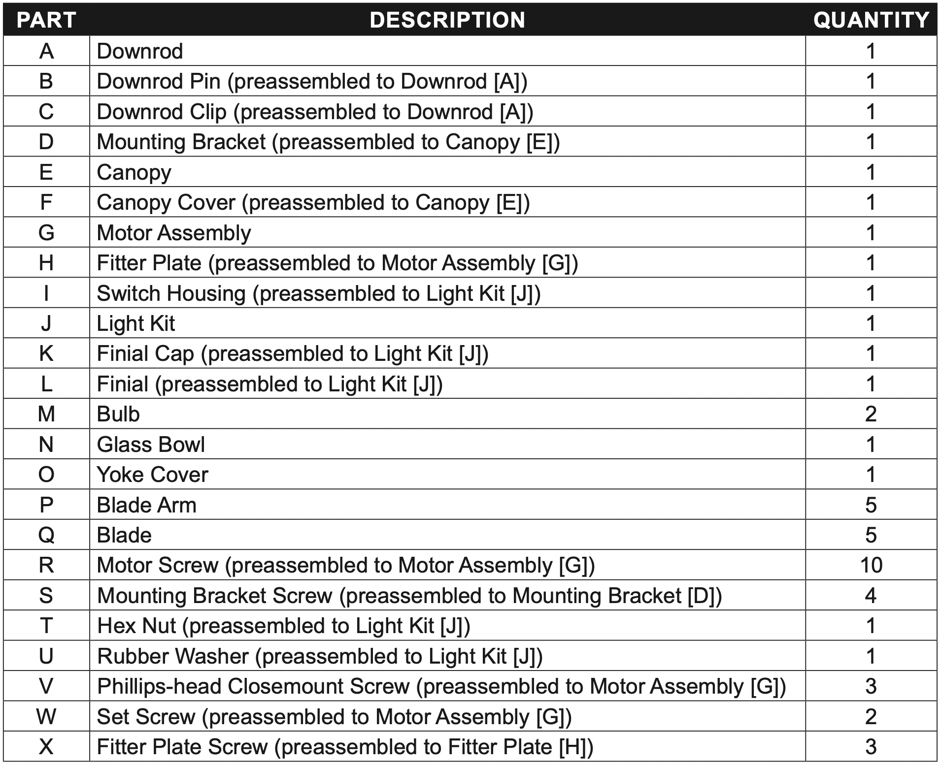
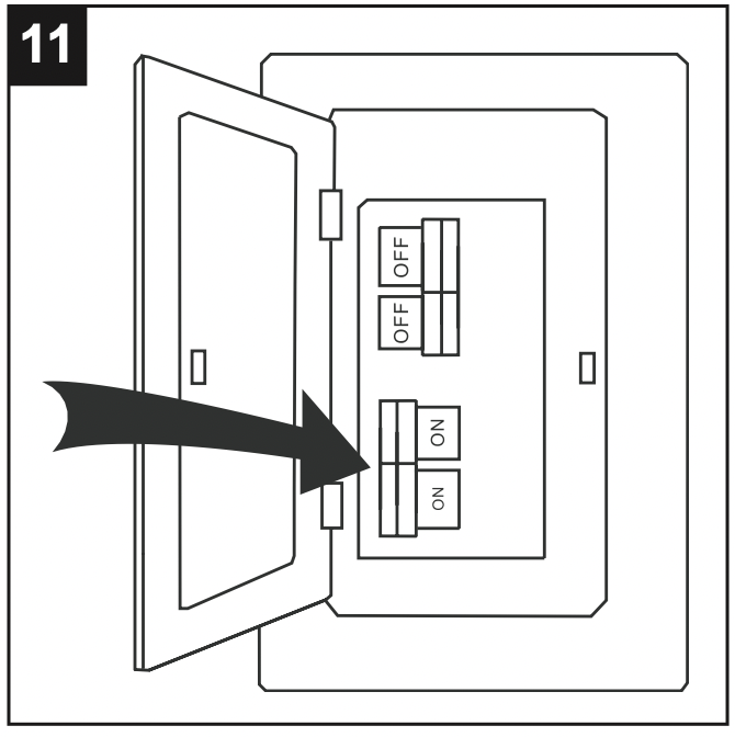
Turn off the circuit breakers and the wall switch to the fan supply line leads. DANGER: Failure to disconnect the power supply prior to installation may result in serious injury or death.
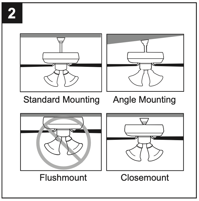
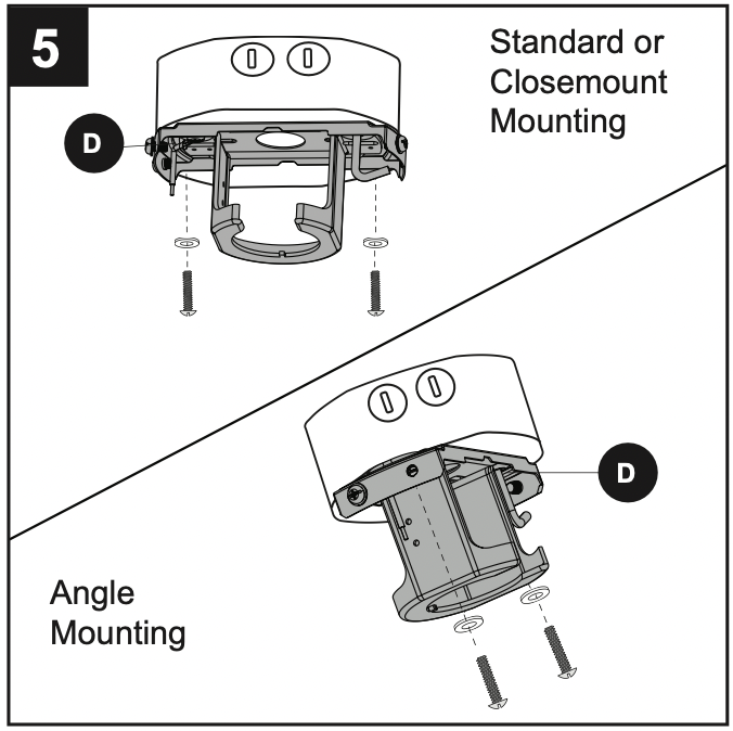
Determine the mounting method to use. Standard mounting is best suited for ceilings 8 ft. or higher. For taller ceilings you may want to use a longer downrod (not included). Angle mounting is best suited for angled or vaulted ceilings. A longer downrod is sometimes necessary to ensure proper blade clearance. Note: If using the angle mount, check to ensure the ceiling angle is not steeper than 16°. Closemount installation is more suitable for ceilings lower than 8 ft. high. Flushmount installation is not available for this item.
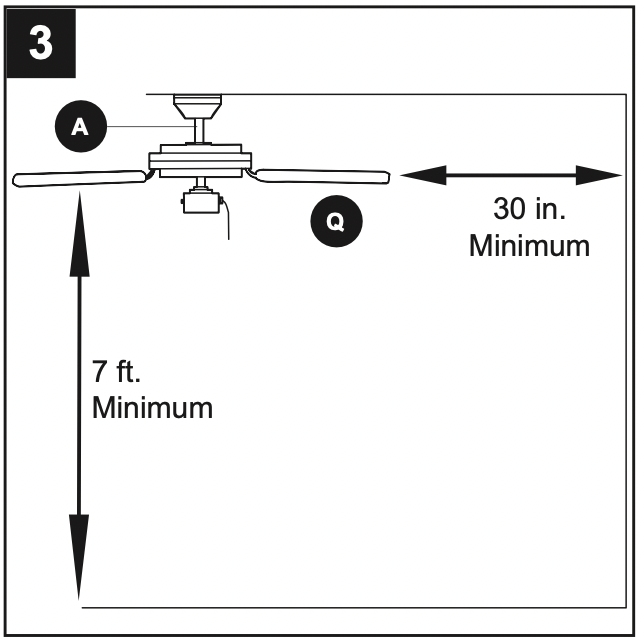
Ensure the blades (Q) will be at least 30 in. from any obstructions. Also check the downrod (A) length to ensure the blades (Q) will be at least 7 ft. above the floor.
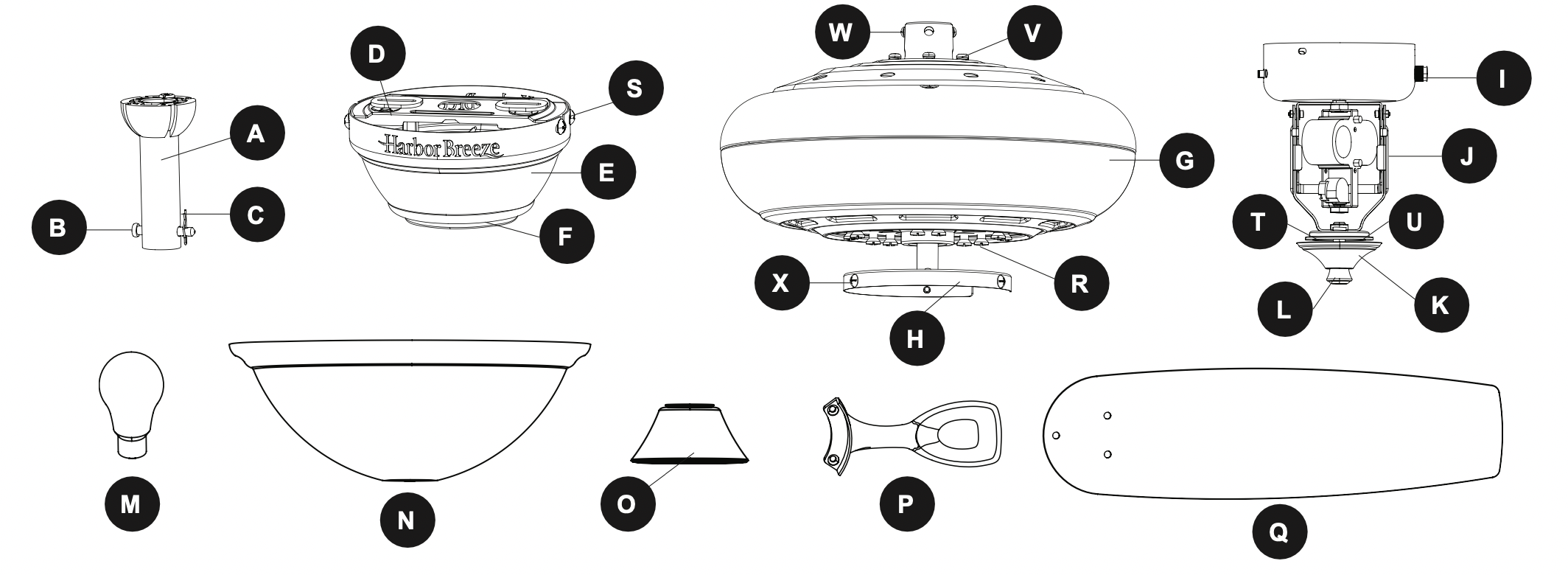
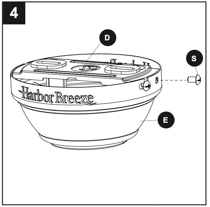
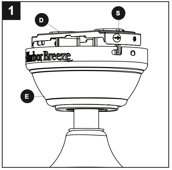
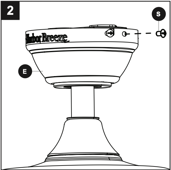
Loosen all four preassembled mounting bracket screws (S), then completely remove the two mounting bracket screws (S) from the round holes of canopy (E). Set aside for later use. Detach mounting bracket (D) from canopy (E).
Attach mounting bracket (D) to outlet box (not included) using screws and washers provided with the outlet box. CAUTION: It is very important to use the proper hardware when installing the mounting bracket (D) as this will support the fan. Important: If using the angle mount, ensure the open end of the mounting bracket (D) is installed facing the higher point of the ceiling.
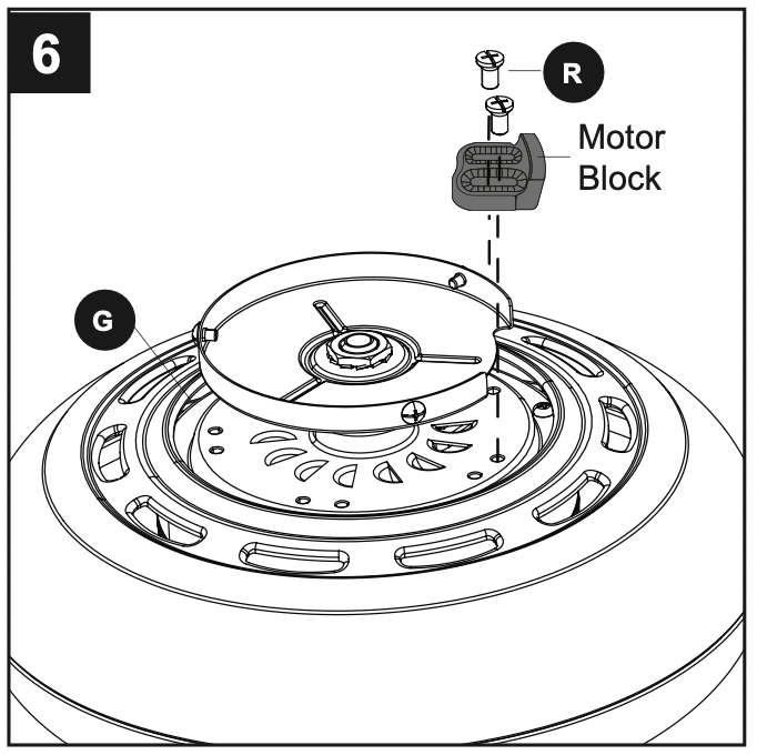
Remove all 10 preassembled motor screws (R) and five preassembled plastic motor blocks from the underside of the motor assembly (G). Discard the motor blocks, but keep the motor screws (R) for later. For Standard or Angle Mounting Instructions, continue to page 9. For Closemount Instructions, proceed to page 11.
STANDARD OR ANGLE MOUNTING INSTRUCTIONS
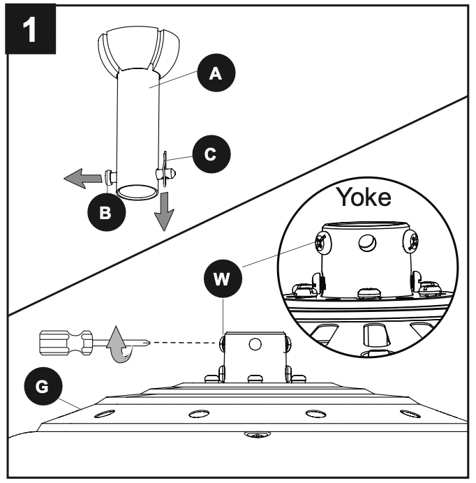
Remove the downrod pin (B) and downrod clip (C) from the downrod (A). Then partially loosen the set screws (W) in the yoke at the top of the motor assembly (G).
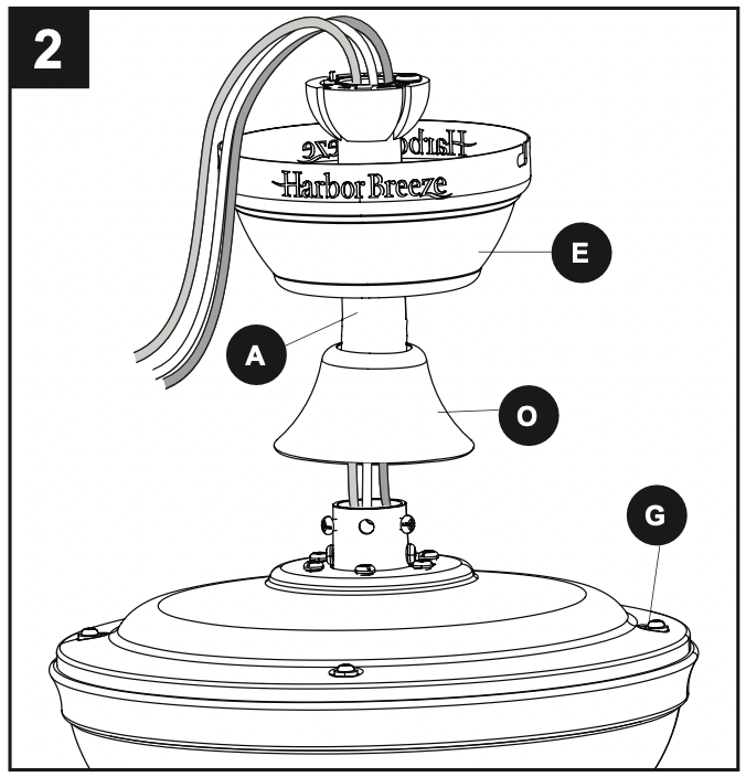
Insert the downrod (A) through the canopy (E) and yoke cover (O). Feed the wires from the motor assembly (G) through the downrod (A).
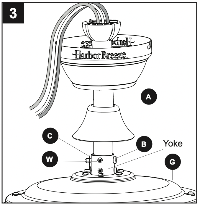
Slide the downrod (A) into the yoke of the motor assembly (G), align the holes, then re-install the downrod clip (C) and downrod pin (B). Secure with set screws (W).
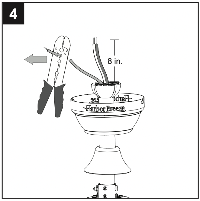
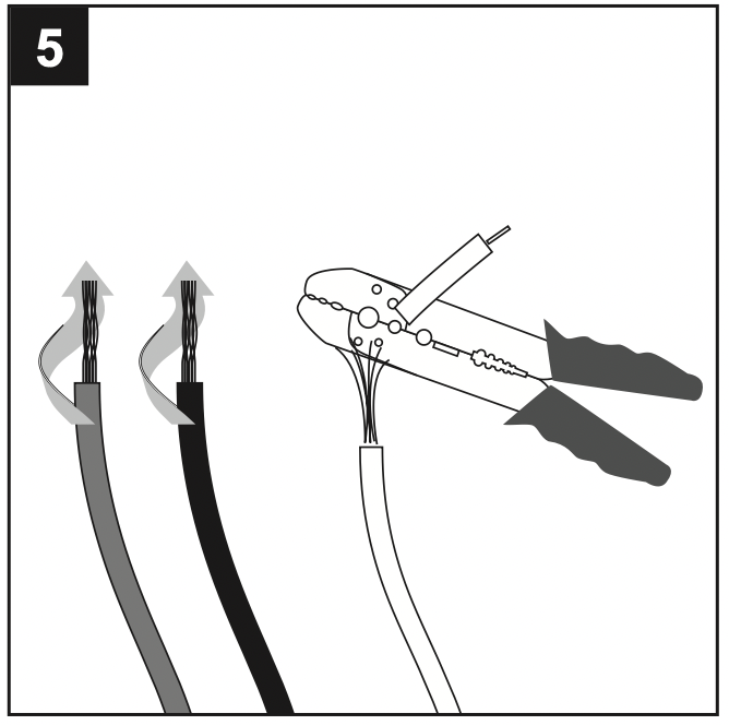
Depending on the length of downrod you use, you may need to cut the lead wires back to simplify the wiring. If you decide to cut back the lead wires, it is suggested you do so in the following manner: Take the lead wires and make sure you have pulled them all the way through the top of the downrod. Measure 8 inches of lead wire, then cut the excess wire off with wire cutters (not included).
Note: If you did not cut back the lead wires in Step 4, Step 5 is not necessary and you may proceed to Step 6. If you decided to cut back the lead wire in Step 4, strip 1/2 in. of insulation from the end of the white wire. Twist the stripped ends of each strand of wire within the insulation with pliers (not included). Repeat this step for black and blue wires.
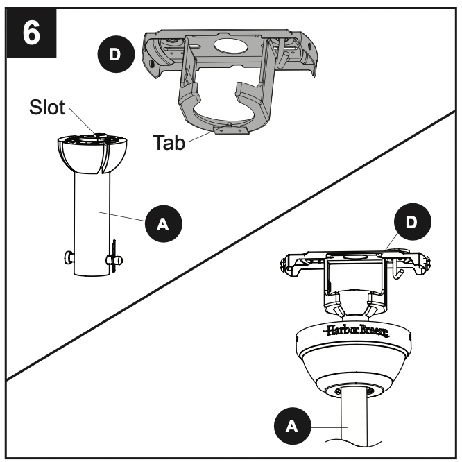
Install the ball end of the downrod (A) into the opening of mounting bracket (D). Align one of the four slots in the ball with the tab in the mounting bracket (D). Note: The downrod (A) should not rotate if installed correctly. DANGER: Failure to align the slot in the downrod (A) with the tab of the mounting bracket (D) may cause the fan to wobble or fall, which could result in serious injury or death.
CLOSEMOUNT INSTRUCTIONS
Helpful Hint: The downrod (A), canopy cover (F) and yoke cover (O) are not used in this type of installation.
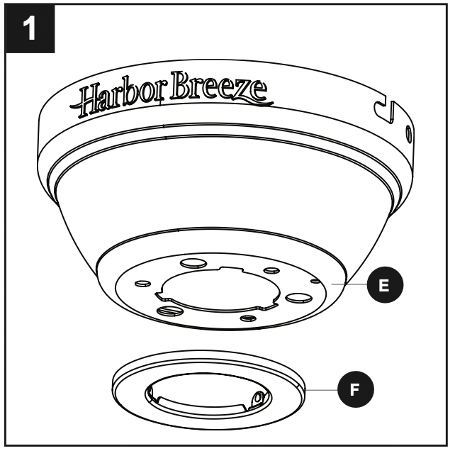
Remove the canopy cover (F) from the bottom of the canopy (E).
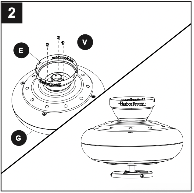
Remove three Phillips-head closemount screws (V) from the top of the motor assembly (G). Align the canopy (E) with the holes in the top of the motor assembly (G), then re-install the Phillips-head closemount screws (V) to secure the canopy (E) to the top of the motor assembly (G).
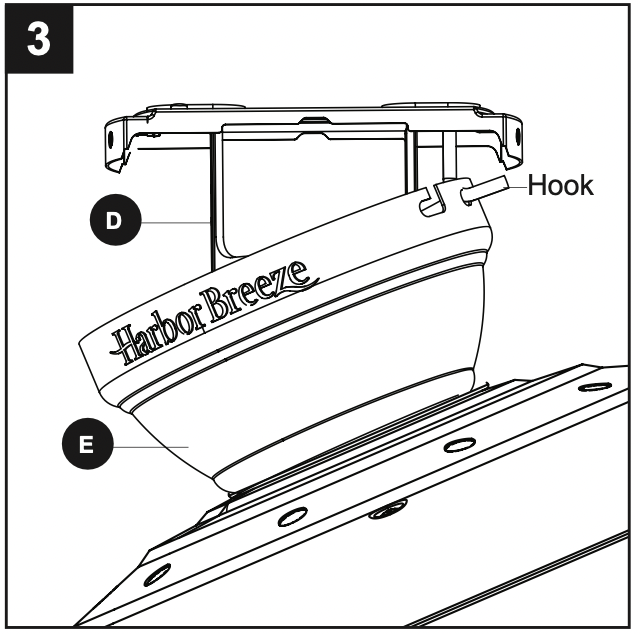
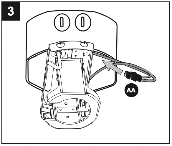
Raise the fan and place the canopy (E) on the hook on the mounting bracket (D), temporarily leaving hands free for the wiring process.
WIRING
WARNING: To reduce the risk of fire, electrical shock or personal injury, wire connectors provided with this fan are designed to accept only one 12-gauge house wire and two lead wires from the fan. If your house wire is larger than 12-gauge and there is more than one house wire to connect to the two fan lead wires, consult an electrician for the proper size wire connectors to use.
CAUTION: Be sure the outlet box is properly grounded or that a ground (green or bare) wire is present.
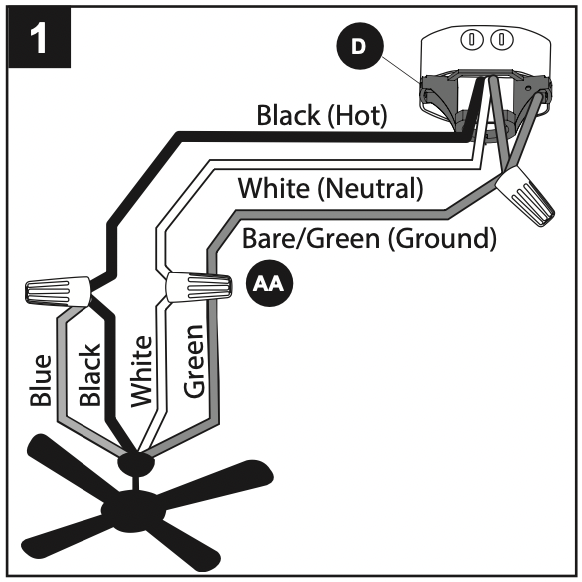
1. Connect household supply and fan wires according to the diagram and these steps:
Connect the Green wire from the downrod (A) and mounting bracket (D) to the Bare/Green supply wire. Note: Closemount installation does not use downrod (A), so there will only be two Green wires to connect.
Connect the White wire from the fan to the White supply wire.
Connect the Black and Blue wires from the fan to the Black supply wire.
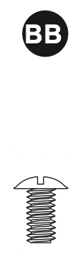
Secure all wiring connections together with wire connectors (AA).
Note: If there is a second hot/power wire coming from the outlet box, connect it to the Blue (light power) fan wire for separate light and fan control.
Note: The Black wire is hot power for the fan. The White wire is common for the fan and light kit. The Blue wire is hot power for light. The Green wire is the ground wire. If household supply wires are different colors than referred to above, it is recommended a professional electrician determines the proper wiring.
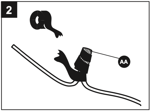
2. Wrap electrical tape (not included) around each individual wire connector (AA) down to the wire.
3. Turn the spliced/taped wires upward and gently push the wires and wire connectors (AA) into the outlet box.
WARNING: Ensure no bare wire or wire strands are visible after making connections. Place the Green and White wire connections on the opposite side of the outlet box from the Black and Blue wire connection(s).
FINAL INSTALLATION
Note: Closemount installation will not use the downrod (A), yoke cover (O) or canopy cover (F).
Align the canopy (E) over the loosened mounting bracket screws (S) preassembled on mounting bracket (D). Place the keyholes of the canopy (E) onto the mounting bracket screws (S) and rotate the canopy (E) clockwise.
Secure the canopy (E) with the mounting bracket screws (S) previously removed (Step 4, page 8). Tighten all mounting bracket screws (S) securely.
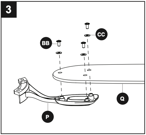
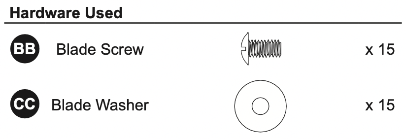
Partially insert the blade screws (BB) along with the blade washers (CC) through the blade (Q) and into the blade arm (P). Tighten each blade screw (BB) with a Phillips screwdriver (not included), starting with the one in the middle. Repeat this step for the remaining blades (Q) and blade arms (P).
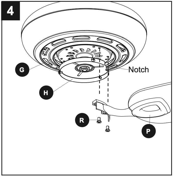
Install the blade arm (P) to the underside of the motor assembly (G) with motor screws (R) previously removed (Step 6, page 8). Tighten with Phillips screwdriver. Repeat for each blade arm (P). Note: The notch in the fitter plate (H) allows screwdriver access to the motor screw holes.
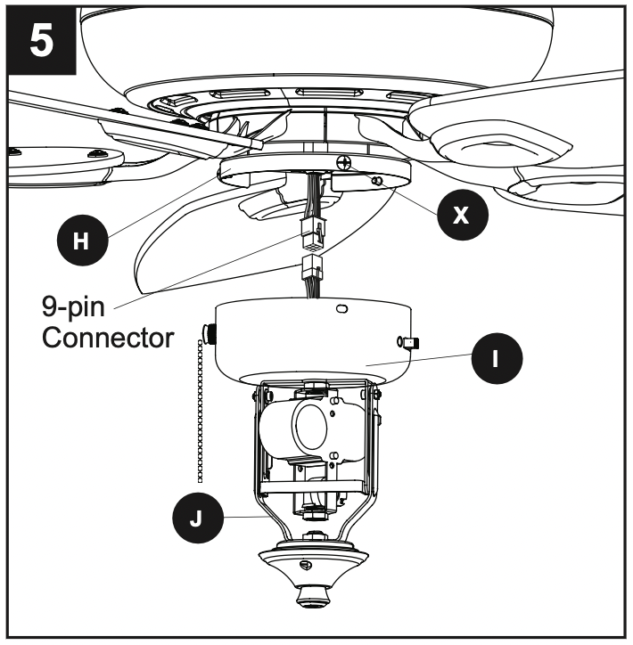
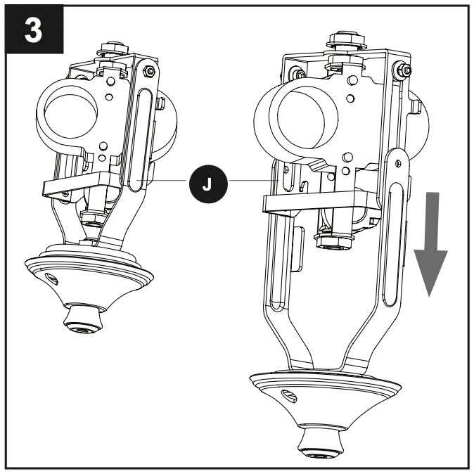
To install the light kit (J), first remove the three fitter plate screws (X) from the fitter plate (H). Then, connect the 9-pin connector from the fan to the 9-pin connector from the switch housing (I). Secure the switch housing (I) along with light kit (J) to the fitter plate (H) using the previously removed fitter plate screws (X).
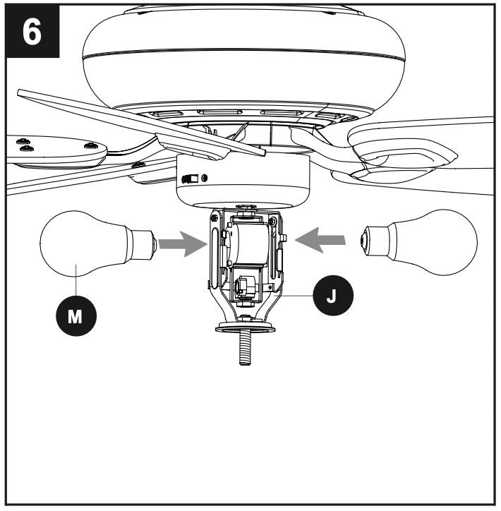
Install the bulbs (M) into the sockets on the light kit (J). IMPORTANT: Make sure to allow the bulbs (M) and light kit (J) to cool before replacing the bulbs.
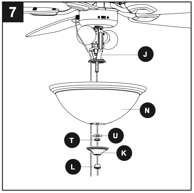
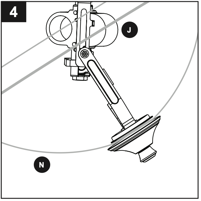
Remove the preassembled finial (L), finial cap (K), hex nut (T) and rubber washer (U) from the light kit (J). Lift the glass bowl (N) onto the threaded rod at the bottom of the light kit (J). Feed the pull chain coming from the grommet in the light kit (J) through the off-center hole in the glass bowl (N). Feed the pull chain coming from the center of the light kit (J) through the center hole in the glass bowl (N). Secure glass bowl (N) with rubber washer (U) and hex nut (T). Then attach finial cap (K) and finial (L).
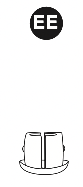
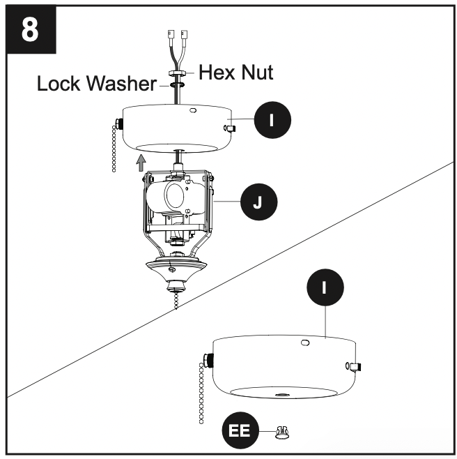
To install the fan without the light kit (J), remove the preassembled hex nut and lock washer from the threaded rod on the inside of the switch housing (I). Remove light kit (J) from the switch housing (I) and discard, then install the plug button (EE) into the center hole of the switch housing (I).
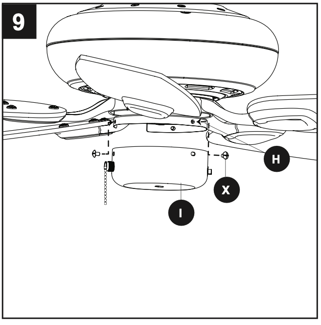
Remove the three fitter plate screws (X) from the fitter plate (H). Then, attach the switch housing (I) to the fitter plate (H) using the fitter plate screws (X).
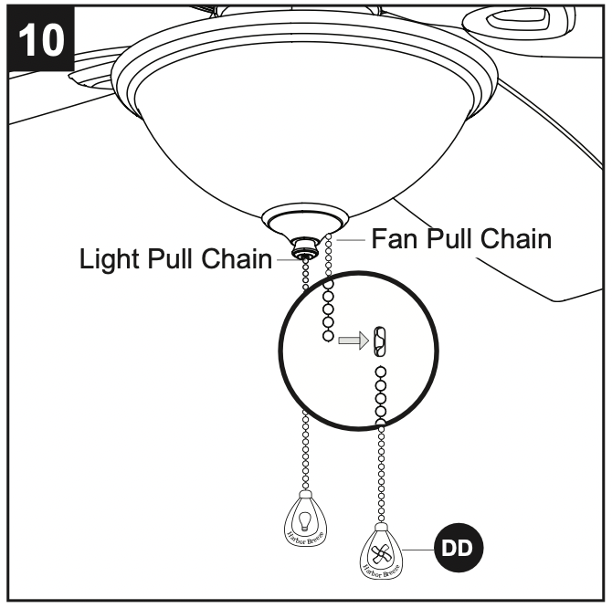
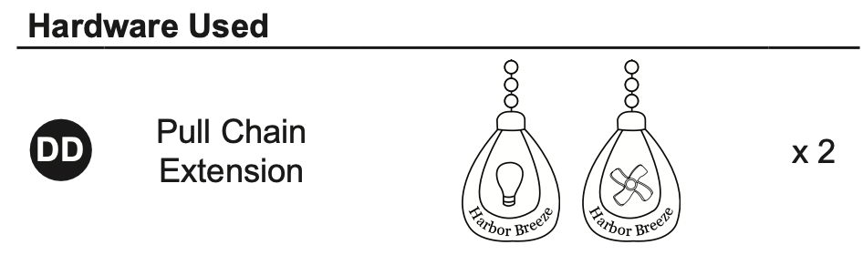
Attach the pull chain extensions (DD) or custom pull chain extensions (not included) to the fan and light pull chains (if applicable).
Turn on power supply to the fan.
OPERATING INSTRUCTIONS
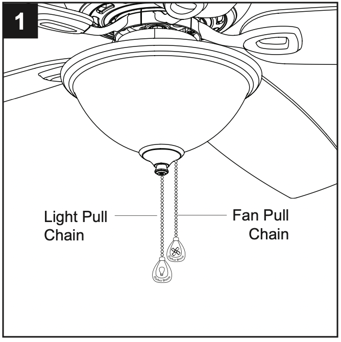
The fan pull chain has four positions to control fan speed. One pull is HIGH, two is MEDIUM, three is LOW and four turns the fan OFF. The light pull chain has two positions to control the light, ON and OFF.
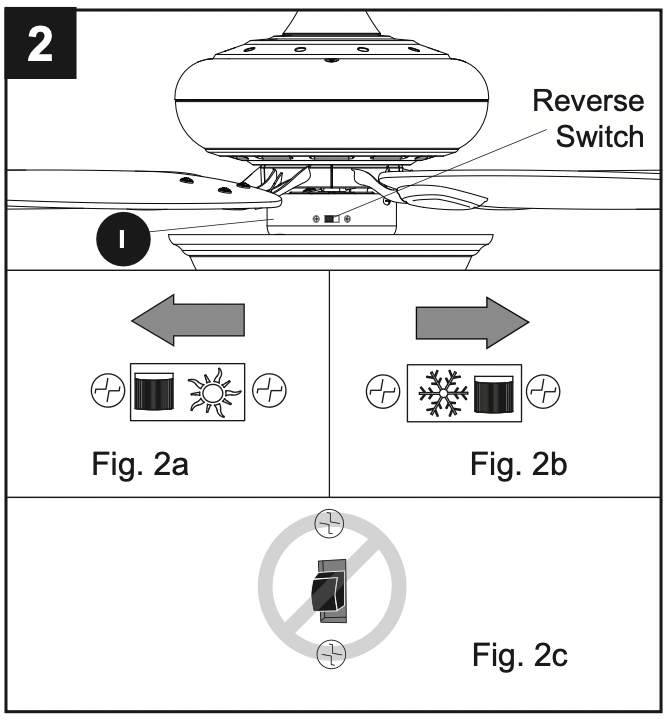
Use the fan reverse switch, located on the switch housing (I), to optimize your fan for seasonal performance. Using a ceiling fan will allow you to raise your thermostat setting in summer and lower your thermostat setting in winter without feeling a difference in your comfort. Note: Wait for the fan to stop before moving the reverse switch. 2a. In warmer weather, push the reverse switch left to display a sun icon, which will result in downward airflow creating a wind chill effect. 2b. In cooler weather, push the reverse switch right to display a snowflake icon, which will result in upward airflow that can help move stagnant, hot air off the ceiling area. Important: The reverse switch must be set either completely left or right in order for the fan to function correctly. If the reverse switch is set in the middle position, the fan will not operate (Fig. 2c).
To change the bulbs or clean the fixture, lower the lower part of the light kit assembly by carefully pushing up on the glass bowl (N). Once it is pushed competely up, tilt the glass bowl (N) and gently lower. Note: The lower arms of the light kit fitter (J) will extend downward approximately 2.5 in., but will not allow the fixture to fall.
Once maintenance has been performed, simply lift the glass bowl (N) up to its original position. The light kit fitter (J) is secure once it clicks into place.
CARE AND MAINTENANCE
At least twice each year, lower the canopy to check the downrod assembly, and then tighten all screws on the fan. Clean the motor assembly with only a soft brush or lint-free cloth to avoid scratching the finish. Clean the blades with a lint-free cloth.
Bulb Replacement: Use 60-watt max. E26-base LED bulbs or CFL equivalents. Halogen bulbs are not recommended for this item.
Important: Shut off the main power supply before you begin any maintenance task. Do not use water or a damp cloth to clean the fan.
TROUBLESHOOTING
PROBLEM
POSSIBLE CAUSE
CORRECTIVE ACTION
The fan does not move.
The reverse switch is notengaged.
The wall switch is turned off.
The power is off or the fuse (breaker) is blown.
There is a faulty wire connection.
Firmly push the reverse switch completely left or right.
Make sure the wall switch is turned on.
Turn the power on or check the fuse (breaker).
Turn the power off and check all connections at the ceiling outlet box.
The fan is noisy.
The blades are loose.
There is a cracked blade.
The wall control is not compatible with the fan.
The outlet box is not secure.
The mounting bracket is not secure.
Check and tighten all screws that hold the fan blades tothe blade arms and the motor.
Replace the cracked blade.
Do not use a full range dimmer switch to control the fan speed.
Ensure the outlet box is secured to the building structure.
Ensure the mounting bracket is secured to the outlet box and that the screws are tight.
There is excessive wobbling.
The bladesand/or blade armsare loose.
The blades are unbalanced.
The fan mounting is not secure.
The fan is too close to the vaulted ceiling.
The set screws on the motor assembly yoke is loose.
Check and tighten all screws that hold the fan blades to the blade arms and the blade arms to the motor.
Switch one blade with a blade from the opposite side. Or balance the fan using a blade balancing kit (sold separately).
Turn off the power. Loosen the canopy and verify that the mounting bracket is secure to the electrical outlet box. The bracket must be flush without movement against the outlet box.
Use a longer downrod (sold separately) or move the fan to another location.
Lift up the yoke cover and tighten the set screws on the yoke until secure.
The fan operates correctly, but the lights are not working.
The bulbs are not installed correctly.
The light kit wire plugs are not connected properly.
There is a faulty wire connection.
Re-install the bulb(s).
Ensure the 9-pin connectors in the light kit are connected properly.
Turn the power off and check all connections at the ceiling outlet box.
#1 Can the light be removed? And if so, does this fan come with a cover plate to cover the hole?
Yes. The switch housing cap is currently attached to the light kit. Once you remove the light kit (instructions are included in owner's manual), you will use the plug button in the hardware bag to fill the hole in the switch housing cap.
#2 Can I mount on a angled ceiling with a 36" down rod
Yes. You may need a angle ceiling adapter depending on the slope of your ceiling
#3 Anyone have a terrible smell in the beginning been running a couple hours but also smelt when I took it out of box.
I apologize for the smell coming from your fan. Please run your fan on high for 36 hours. The heat from the motor will cure coating on the motor and the smell will dissipate. There's no safety issue, but I apologize for the inconvenience.
#4 what type of light switch does this model have?
The light is turned off and on with a pull chain. If the outlet box where your fan is wired has two hot wires (two wall switches), then you can control the fan and the light separately using the wall switches.
#5 Can I flush mount this fan? The rod it came with extends it too low.
Yes, you can mount the Coastal Creek without the downrod.