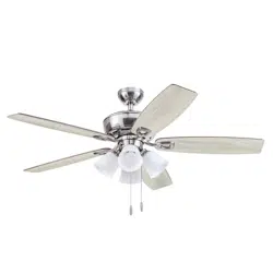
User Manual Ceiling Fan
Package Contents
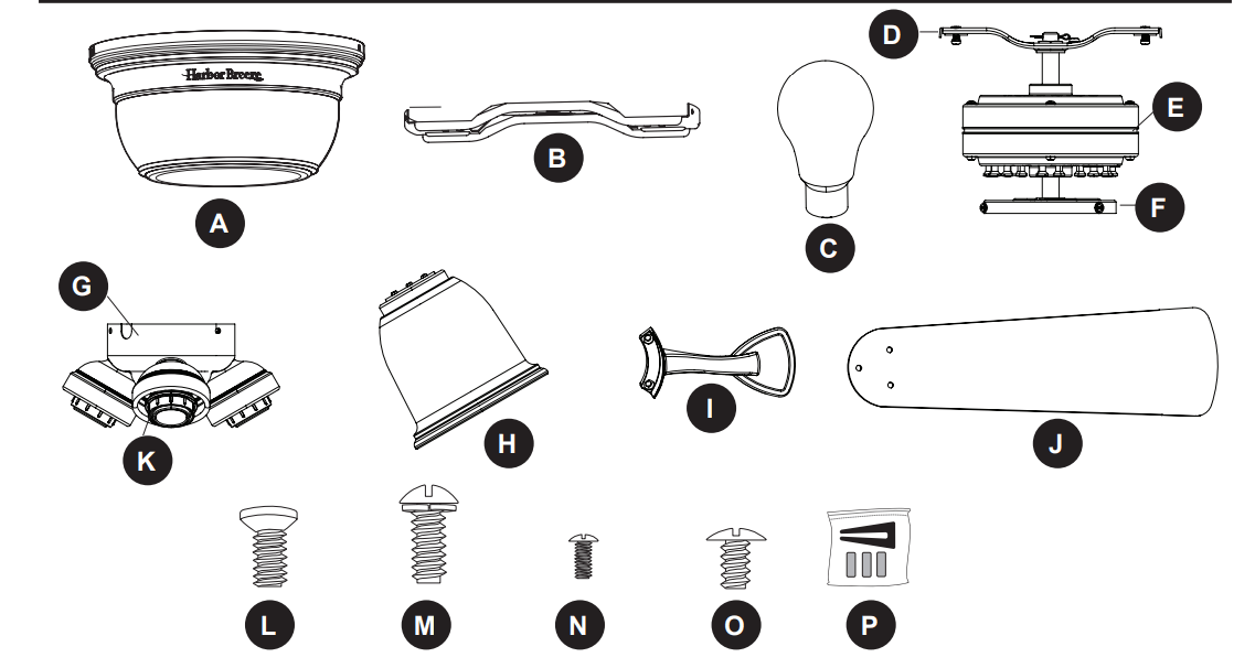
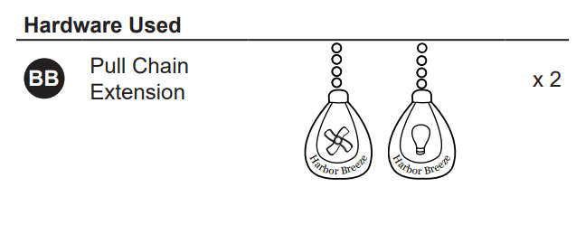
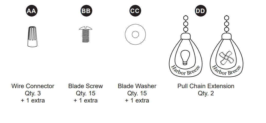
HARDWARE CONTENTS (shown actual size)
INITIAL INSTALLATION
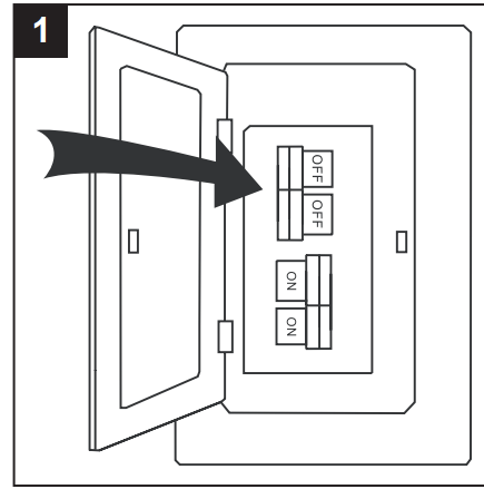
1. Turn off the circuit breakers and the wall switch to the fan supply line leads.
- DANGER: Failure to disconnect the power supply prior to installation may result in serious injury or death.
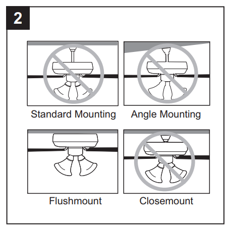
2. This fan is intended for Flushmount installation.
- Standard Mounting, Angle Mounting, and Closemount installations are not available.
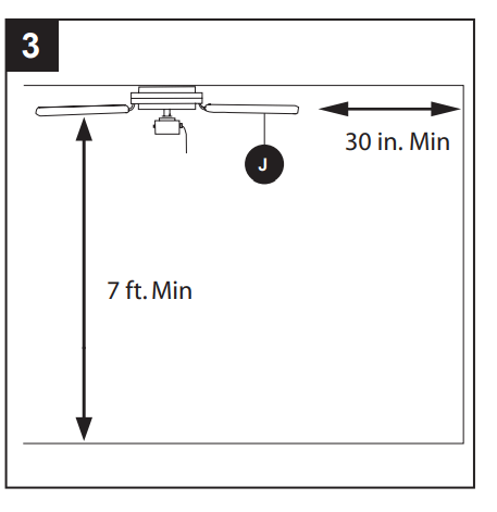
3. Ensure the blades (J) will be at least 30 in. from any obstructions and will be at least 7 ft. above the floor.
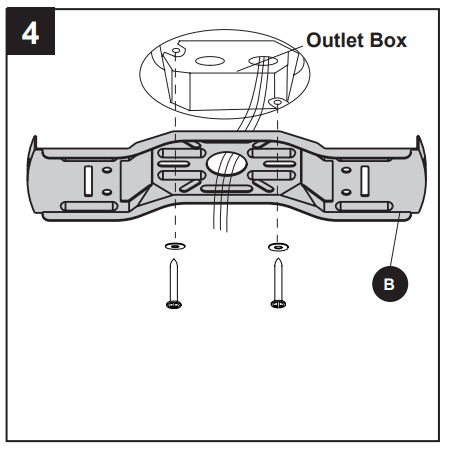
4. Secure the upper mounting bracket (B) to the outlet box (not included) using screws and washers provided with the outlet box.
- CAUTION: It is very important that you use the proper hardware when installing the upper mounting bracket (B) as it will support the fan
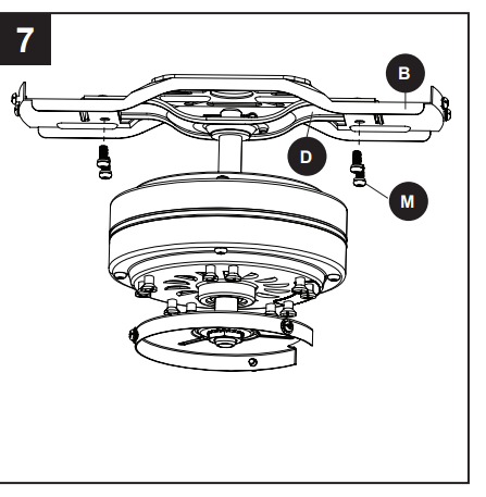
5. Remove the lower bracket screws (M) from underneath the lower mounting bracket (D).
- Note: Make sure to keep loose hardware separate to avoid confusion during installation.
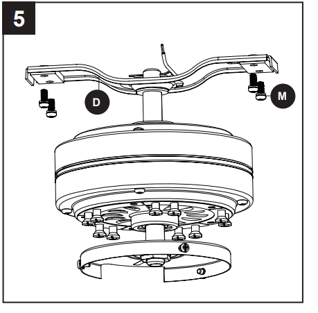
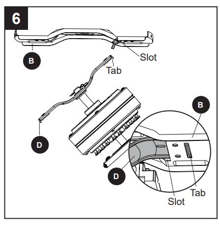
6. Place one tab of the lower mounting bracket (D) into a slot in the upper mounting bracket (B). Then slide the second tab of the lower mounting bracket (D) into the second slot on the upper mounting bracket (B) until all four holes are in alignment.
7. Re-install the previously removed lower bracket screws (M) to secure the lower mounting bracket (D) and the upper mounting bracket (B).
WIRING
WARNING: To reduce the risk of fire, electrical shock or personal injury, wire connectors provided with this fan are designed to accept only one 12-gauge house wire and two lead wires from the fan. If your house wire is larger than 12 gauges and/or there is more than one house wire to connect to the two fan lead wires, consult an electrician for the proper size wire connectors to use.
CAUTION: Be sure the outlet box is properly grounded or that a Ground (Green or Bare) wire is present.
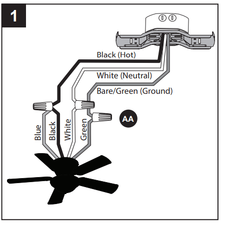
1. Connect household supply and fan wires according to the diagram and these steps:
- Connect the Green wire from fan to the Bare/Green supply wire.
- Connect the White wire from the fan to the White supply wire.
- Connect the Black and Blue wires from the fan to the Black supply wire.
- Secure all wiring connections together with wire connectors (AA).
- Note: If there is a second hot/power wire coming from the outlet box, connect it to the blue (light power) fan wire for separate light and fan control.
- Note: The Black wire is hot power for the fan. The White wire is common for the fan and light kit. The Blue wire is hot power for light. The Green wire is the ground wire. If household supply wires are different colors than referred to above, it is recommended a professional electrician determines the proper wiring.
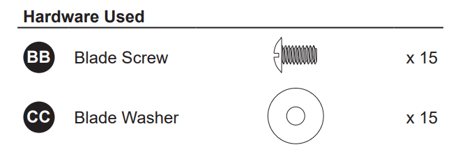
Hardware Used

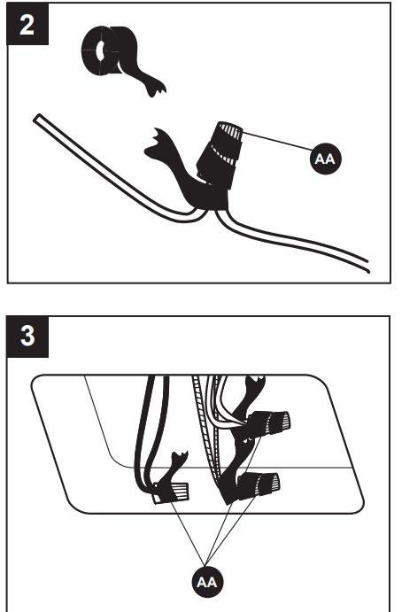
2. Wrap electrical tape (not included) around each individual wire connector (AA) down to the wire.
3. Turn the spliced/taped wires upward and gently push the wires and wire connectors (AA) into the outlet box.
- WARNING: Ensure no bare wire or wire strands are visible after making connections. Place the Green and White wire connections on the opposite side of the outlet box from the Black and Blue wire connections.
FINAL INSTALLATION
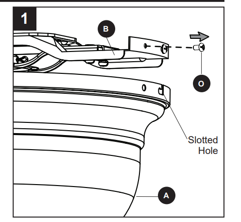
- Temporarily lift the motor housing (A) to the upper mounting bracket (B) to determine which two motor housing screws (O) in the sides of the upper mounting bracket (B) align with the slotted holes in the top edge of the motor housing (A). Partially loosen the two motor housing screws (O) that align with the slotted holes. Remove the other two motor housing screws (O) from the upper mounting bracket (B).
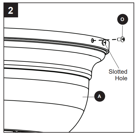
- Slide the motor housing (A) over the motor (E), aligning the slotted holes in the motor housing (A) with the loosened motor housing screws (O) in the upper mounting bracket (B). Twist the motor housing (A) clockwise to lock. Then re-insert the two previously removed motor housing screws (O) and securely tighten all screws.
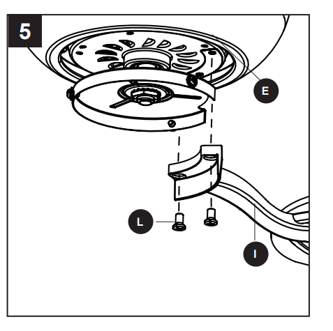
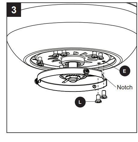
- Remove the 10 motor screws (L) from the motor (E) and save for later use.
- Note: The notch in the fitter plate allows a Phillips screwdriver (not included) access to motor screws (L).
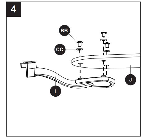
- Partially insert the blade screws (BB) along with the blade washers (CC) through the blade (J) and into the blade arm (I). Tighten each blade screw (BB) with a Phillips screwdriver, starting with the one in the middle. Repeat this step for the remaining blades (J) and blade arms (I).
- Install the blade arm (I) to the underside of the motor (E) with motor screws (L) previously removed (Step 3, page 10). Tighten with Phillips screwdriver. Repeat for each blade arm (I).
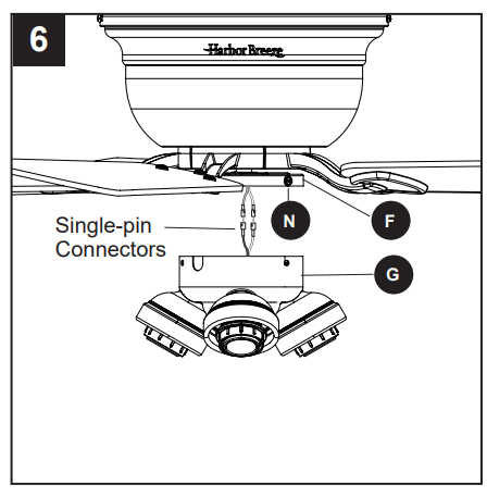
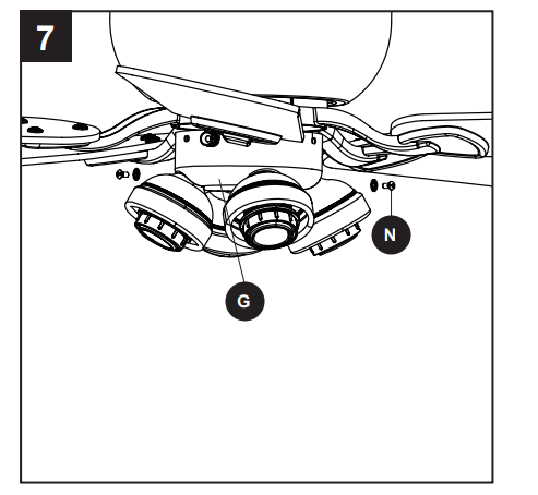
- Remove the fitter plate screws (N) preassembled to the fitter plate (F). Then, connect the single-pin connectors from the fitter plate (F) and the light kit (G) -- blue to black and white to white.
- Secure the light kit (G) to the fitter plate (F) by reinstalling the fitter plate screws (N).
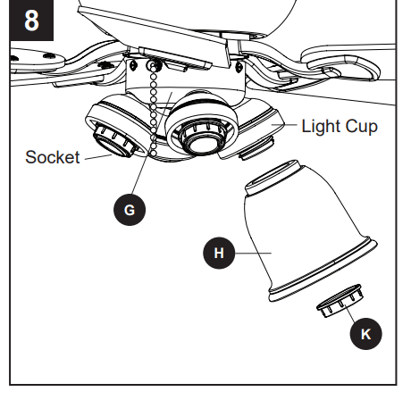
- Unscrew the socket ring (Q) from the socket of the light kit (G). Then lift the glass shade (H) into the light cup. Secure the glass shade (H) by reinstalling the socket ring (K).
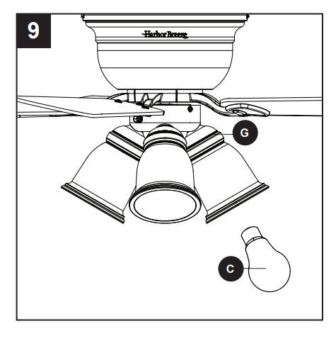
- Install bulbs (C) into the sockets of the light kit (G).
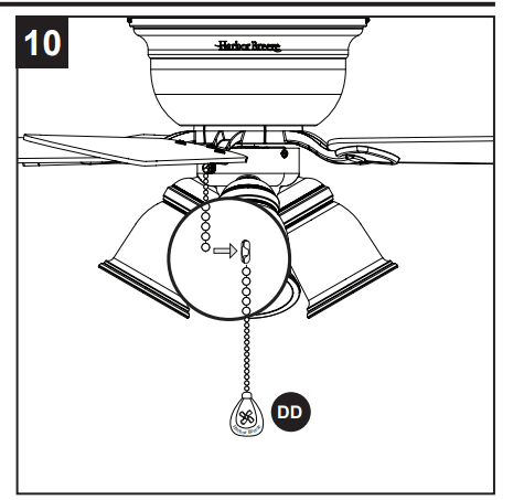
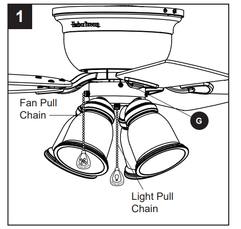
- Attach the pull chain extensions (DD) or custom pull chain extensions (not included) to the fan and light pull chains (if applicable).
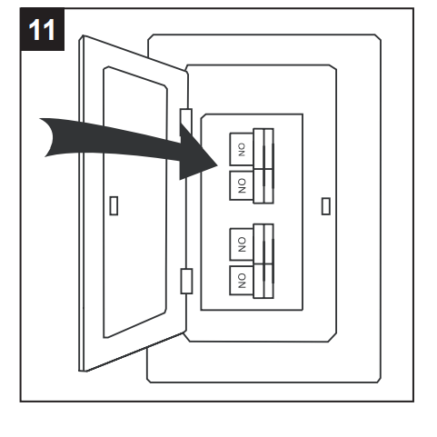
- Turn on power supply to the fan.
- Assembly is complete.
OPERATING INSTRUCTIONS
- The pull chain on the side of the light kit (G) has four positions to control the fan speed. One pull is HIGH, two is MEDIUM, three is LOW, and four turns the fan OFF. The pull chain in the center of the light kit (G) turns the lights ON and OFF.
- Using a ceiling fan will allow you to raise your thermostat setting in summer and lower your thermostat setting in winter without feeling a difference in your comfort. Note: Wait for the fan to stop before moving the reverse switch located on the fitter plate (F).
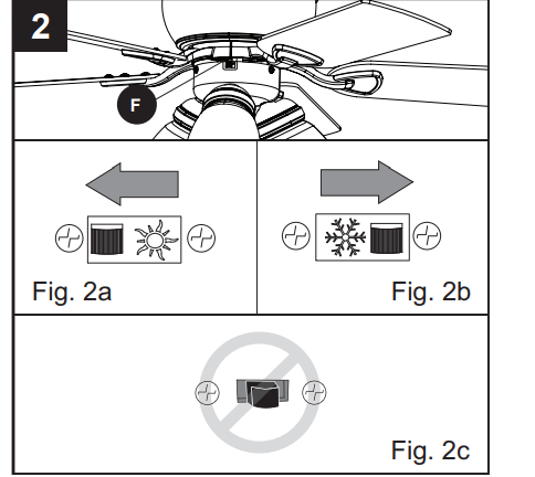
- In warmer weather, push the reverse switch left to display a sun icon, which will result in downward airflow creating a wind chill effect (Fig. 2a).
- In cooler weather, push the reverse switch right to display a snowflake icon, which will result in upward airflow that can help move hot air off the ceiling area (Fig. 2b).
- Important The reverse switch must be set either completely left or right in order for the fan to function correctly. If the reverse switch is set in the middle position, the fan will not operate (Fig. 2c).
CARE AND MAINTENANCE
At least twice each year, tighten all screws on the fan. Clean the motor housing with only a soft brush or lint-free cloth to avoid scratching the finish. Clean the blades with a lint-free cloth.
Bulb Replacement: Use 60-watt max. E26-base LED, CFL or incandescent bulbs. Halogen bulbs are not recommended for this item.
Important Shut off the main power supply before you begin any maintenance tasks. Do not use water or a damp cloth to clean the ceiling fan
TROUBLESHOOTING
- The fan does not move.
- The power is off or the fuse is blown.
- Turn the power on or check the fuse.
- There is a faulty wire connection.
- Turn the power off. Loosen the canopy and check all connections.
- The plugs are not connected properly.
- Check that the connectors from the light kit and fan are connected properly.
- The reverse switch is not completely engaged.
- Push the reverse switch completely to the left or right.
- There is excessive wobbling.
- The blades and/or blade are loose.
- Check and tighten all screws that hold the fan blades to the blade arms and the blade arms to the motor.
- The blades are unbalanced.
- Switch one blade with a blade from the opposite side. Or balance the fan using the blade balancing kit (P).
- The fan mounting is not secure.
- Turn off the power. Loosen the motor housing and verify the upper mounting bracket is secure to the electrical outlet box. The bracket must be flush without movement against the outlet box.
- The fan operates correctly, but the lights are not working.
- The bulbs are not installed correctly.
- The light kit wire plugs are not connected properly.
- . Ensure the single-pin connectors in the light kit are connected properly
- There is a faulty wire connection.
- Turn the power off and check all connections at the ceiling outlet box.
- The fan is noisy.
- The blades are loose.
- Check and tighten all screws that hold the fan blades to the blade arms and the motor.
- There is a cracked blade.
- Replace the cracked blade.
- The outlet box is not secure.
- Ensure the outlet box is secured to the building structure.
- The mounting bracket is not secure.
- Ensure the mounting bracket is secured to the outlet box and that the screws are tight.
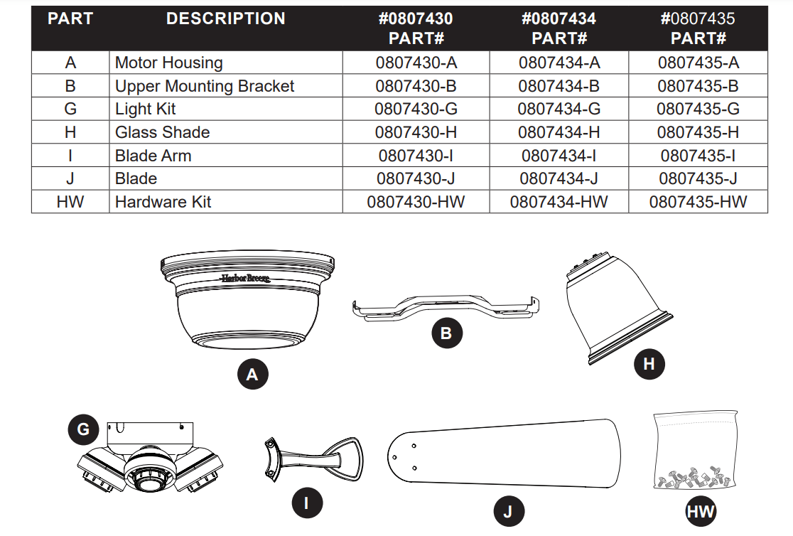
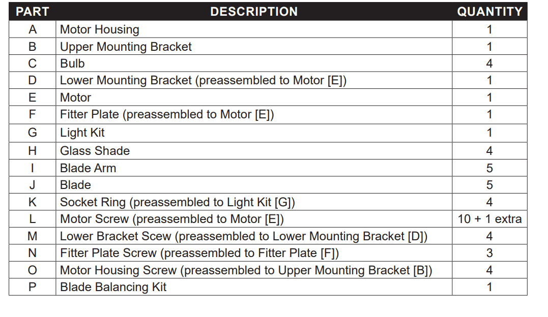
REPLACEMENT PARTS LIST
For replacement parts, call the customer service department at 1-800-643-0067, 8 a.m. - 6 p.m., EST, Monday - Thursday, 8 a.m. - 5 p.m., EST, Friday.