USER MANUAL SAIL STREAM CEILING FAN
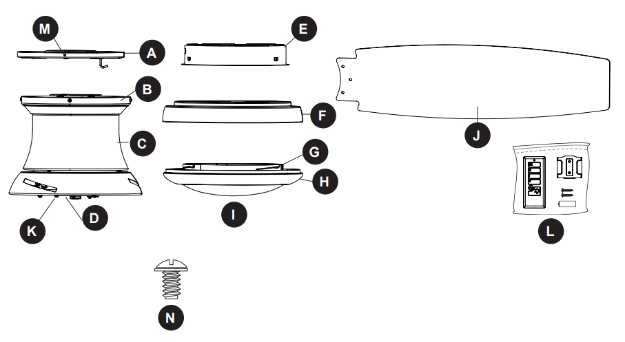
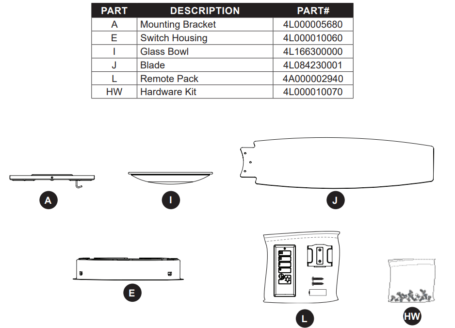
PACKAGE CONTENTS
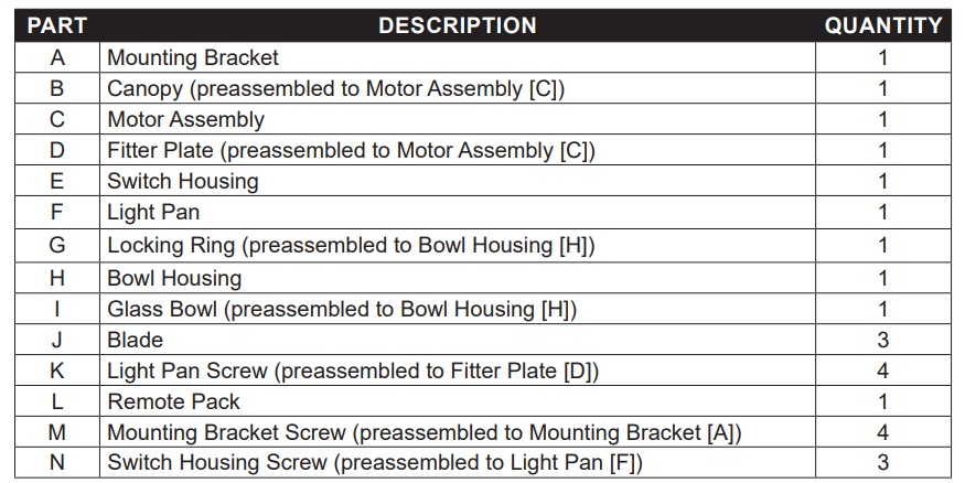
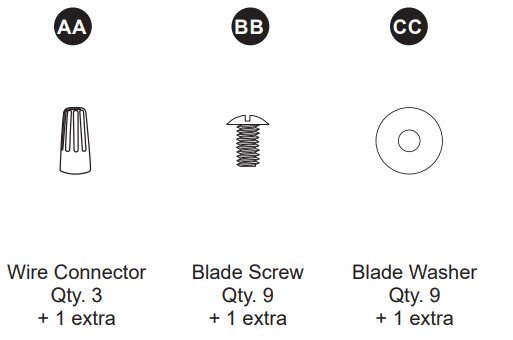
HARDWARE CONTENTS
PREPARATION
Before beginning the assembly of this product, ensure that all parts are present. Compare all parts with the package contents list and hardware contents list. If any part is missing or damaged, do not attempt to assemble the product.
Estimated Assembly Time: 120 minutes
Tools Required for Assembly (not included): Electrical Tape, Phillips Screwdriver, Pliers, Safety Glasses, Step Ladder, Wire Cutters and Wire Strippers
Helpful Tools (not included): AC Tester Light, Tape Measure and Wiring Handbook
INITIAL INSTALLATION
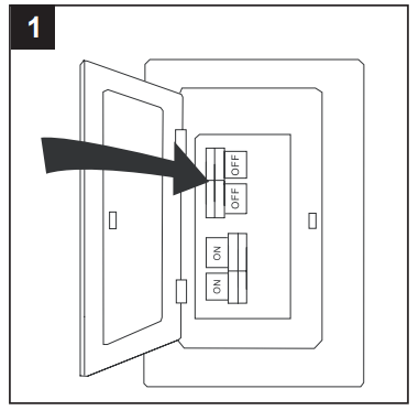
- Turn off the circuit breakers and the wall switch to the fan supply line leads.
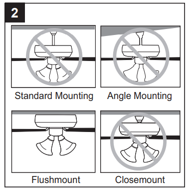
- This fan is intended for Flushmount Installation. Standard Mounting, Angle Mounting, and Closemount installations are not available.
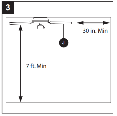
- Ensure the blades (J) will be at least 30 in. from any obstructions and will be at least 7 ft. above the floor.
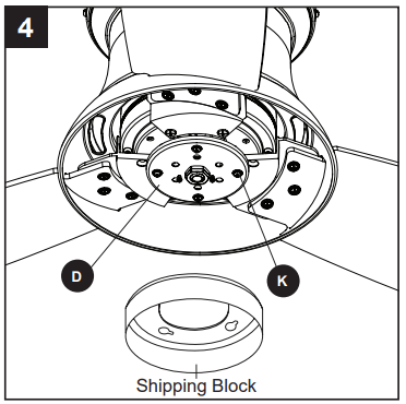
- Loosen the four light pan screws (K) preassembled to the fitter plate (D). Then, turn the orange shipping block counterclockwise and remove. Discard the shipping block.
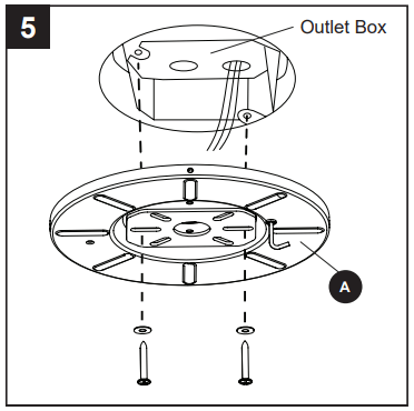
- Feed the supply wires from the outlet box through the center hole in the mounting bracket (A). Then, secure the mounting bracket (A) to the outlet box (not included) using screws and washers provided with the outlet box. CAUTION: It is very important you use the proper hardware when installing the mounting bracket (A) as it will support the fan.
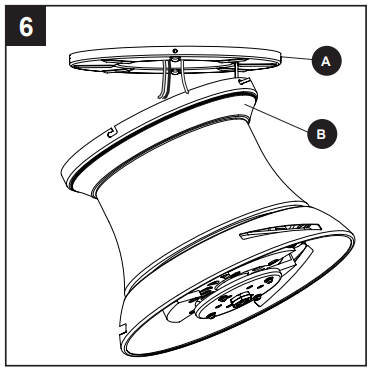
- Raise the fan and place the canopy (B) on the hook on the mounting bracket (A), temporarily leaving hands free for the wiring process.
WIRING
WARNING: To reduce the risk of fire, electrical shock or personal injury, wire connectors provided with this fan are designed to accept only one 12-gauge house wire and two lead wires from the fan. If your house wire is larger than 12-gauge and/or there is more than one house wire to connect to the two fan lead wires, consult an electrician for the proper size wire connectors to use.
CAUTION: Be sure the outlet box is properly grounded or that a ground (green or bare) wire is present.
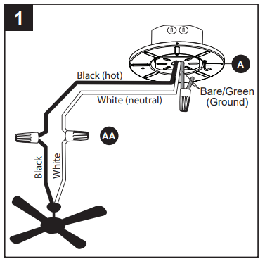
1. Connect supply and fan wires according to the diagram and these steps:
- Connect the Green wire from the mounting bracket (A) to the Bare/Green (ground) supply wire.
- Connect the White wire from the fan to the White (neutral) supply wire.
- Connect the Black wire from the fan to the Black (hot) supply wire. Secure all wiring connections together with wire connectors (AA).
Note: The Black wire is hot power for the fan. The White wire is neutral for the fan and light kit. The Green wire is the ground wire. If supply wires are different colors than referred to above, a professional electrician should determine the proper wiring.
Hardware Used
 Wire Connector
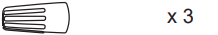
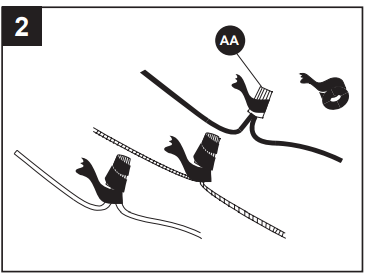
2. Wrap electrical tape (not included) around each individual wire connector (AA) down to the wire.
3. Turn the spliced/taped wires upward and gently push the wires and wire connectors (AA) into the outlet box.
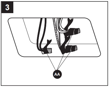
 WARNING: Ensure no wire strands are visible after making connections. Place the Green and White wire connections on the opposite side of the outlet box from the Black.
FINAL INSTALLATION
1. Loosen all four mounting bracket screws (M), then completely remove two mounting bracket screws (M) from opposite sides of the mounting bracket (A). Slide the canopy (B) over the mounting bracket (A), aligning the slotted holes in the canopy (B) with the pre-loosened mounting bracket screws (M) in the mounting bracket (A). Twist the canopy (B) clockwise to lock. Then re-insert the mounting bracket screws (M) and securely tighten all screws. 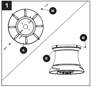
2. Insert blade (J) through slot in the side of the motor assembly (C), ensuring the “THIS SIDE UP” label faces the ceiling. Align the holes of one blade (J) with three blade screw holes in underside of the motor assembly (C). Secure blade (J) with three blade screws (BB) and blade washers (CC). Repeat for the remaining blades (J). 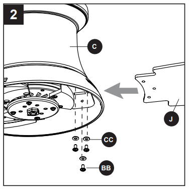
3. Remove one of the light pan screws (K) from the fitter plate (D). Then, insert the wires from the center of the fitter plate (D) through the hole in the light pan (F). Align the light pan (F) over the previously loosened light pan screws (K), then place the keyholes of the light pan (F) clockwise. Secure the light pan (F) with the previously removed light pan screw (K). Tighten all four light pan screws (K). 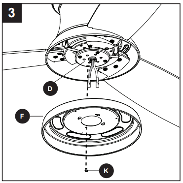
Hardware Used
 Blade Screw
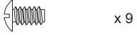
 Blade Washer
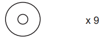
4. Remove one of the switch housing screws (N) from the light pan (F), and loosen (do not remove) the other two screws. Connect the single-pin connector from the center of the fitter plate (D) to the single-pin connector from the switch housing (E) -- blue to black and white to white. 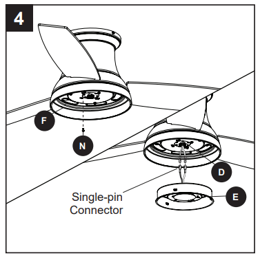
5. Align the switch housing (E) over the loosened switch housing screws (N) preassembled on the switch housing (E), then place the keyholes of the switch housing (E) onto the switch housing screws (N) and rotate the switch housing (E) clockwise. Secure the switch housing (E) with the previously removed switch housing screw (N). Tighten all three switch housing screws (N). 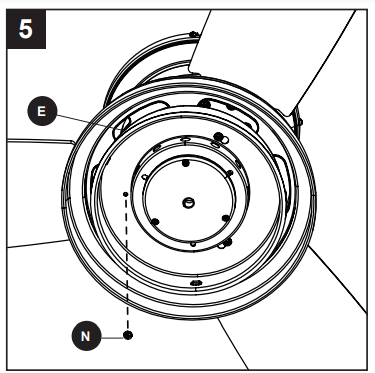
6. Align the notches in the switch housing (E) with the grooves in the locking ring (G) preassembled to bowl housing (H). Then, twist the locking ring (G) tightly in a clockwise direction until it is secure. Turn on the circuit breakers and the wall switch to the fan supply lead lines. 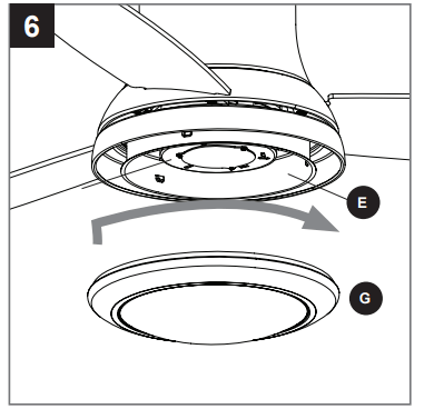
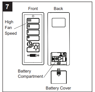
7. Remove the battery cover from the back of the remote found in remote pack (L). Insert the battery from remote pack (L) into the remote; ensure polarity of battery matches the polarity indicated in the battery compartment -- positive (+) to positive (+) and negative (-) to negative (-). Replace the battery cover and press the high fan speed button on the remote to ensure the remote turns on the fan.
Note: If remote does not turn on fan, see TROUBLESHOOTING
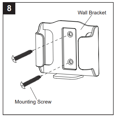
8. If desired, the wall bracket in remote pack (L) can be installed to a wall using the provided mounting screws. Store the remote on the wall bracket when not in use.
OPERATING INSTRUCTIONS
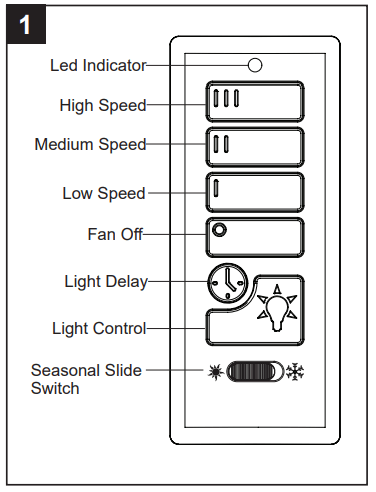
1. To operate the fan using the remote from remote pack (L), press and release the following buttons:
III - High speed
II - Medium speed
I - Low speed
Fan Off - Turns power to fan of
Light Delay - Tap the light delay button, which will turn off the light after one minute. Tap the light control button to exit light delay mode.
Light Control - Tap the light control button to turn the light off and on. Press and hold light control button to dim or brighten the lights.
Seasonal Slide Switch - In warmer weather, push the seasonal slide switch left toward sun icon, which will result in downward airflow creating a wind chill effect.
In cooler weather, push the seasonal slide switch right toward the snowflake icon, which will result in upward airflow that can help move hot air off the ceiling.
Important: Wait for the fan to stop before moving the seasonal slide switch. The seasonal slide switch must be set either completely left or right in order for the fan to function correctly. If the switch is set in the middle position, the fan will not operate.
Low Battery Indicator - LED Indicator will flash for one minute as a reminder to replace the 12-volt battery.
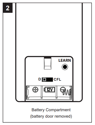
2. Remove battery door from back of the remote from remote pack (L) to access the following:
D/CFL Switch - set to “D” at the factory. The switch should remain in the “D” position.
LEARN - Syncs remote to receiver (see troubleshooting for instructions).
CARE AND MAINTENANCE
- At least twice each year, tighten all screws on the fan. Clean the motor housing with only a soft brush or lint-free cloth to avoid scratching the finish. Clean the blades with a lint-free cloth.
- Battery Replacement: Use A23 12-volt battery. Exhausted batteries should be removed from the remote.
Important Shut off the main power supply before you begin any maintenance tasks. Do not use water or a damp cloth to clean the ceiling fan.
TROUBLESHOOTING
The fan does not move.
- The power is off or the fuse is blown.
- Turn the power on or check the fuse.
- There is a faulty wire connection.
- Turn the power off. Loosen the canopy and check all connections.
- The plugs are not connected properly.
- Check that the connectors from the light kit and fan are connected properly.
- The reverse switch is not completely engaged.
- Push the seasonal slide switch completely to the left or right.
There is excessive wobbling.
- The blades and/or blade arms are loose.
- Check and tighten all screws that hold the fan blades to the blade arms and the blade arms to the motor
- The blades are unbalanced.
- Switch one blade with a blade from the opposite side. Or balance the fan using a blade balancing kit (sold separately).
- The fan mounting is not secure
- Turn off the power. Loosen the motor housing and verify the upper mounting bracket is secure to the electrical outlet box. The bracket must be flush without movement against the outlet box.
The fan operates correctly, but the lights are not working.
- The light kit wire plugs are not connected properly.
- Ensure that the male and female plugs in the light kit fitter are connected properly.
- There is a faulty wire connection
- Turn the power off and check all connections at the ceiling outlet box.
The fan is noisy
- The blades are loose.
- Check and tighten all screws that hold the fan blades to the blade arms and the motor.
- There is a cracked blade.
- Replace the cracked blade.
- The outlet box is not secure.
- Ensure the ceiling outlet box is secured to the building structure.
- The mounting bracket is not secure.
- Ensure the mounting bracket is secured to the outlet box and that the screws are tight.
Remote control does not work.
- Power surge may have cleared memory and remote needs to be re-synced to the receiver.
- After installation is complete, switch the power off and back on again. Within 30 seconds, press and hold the “LEARN” button, located in the battery compartment, for 5 seconds. Fan will turn on at low speed and light off. This confirms that the SMART SYNC is active.
- Battery in remote control needs to be replaced.
- Insert new 12V battery in battery compartment of the remote control
- Interface from another remote.
- If there are several fans in close proximity, turn power off to other fans and re-sync the remote
LIFETIME LIMITED WARRANTY
- The manufacturer warrants this fan to be free from defects in workmanship and materials present at time of shipment from the factory for a lifetime from the date of purchase by the original purchaser. The retailer also warrants that all other fan parts, excluding any glass or plastic blades, to be free from defects in workmanship and material at the time of shipment from the factory for a period of one year after the date of purchase by the original purchaser. The manufacturer agrees to correct such defects without charge or at its option replace the ceiling fan with a comparable or superior model.
- To obtain warranty service, present a copy of the receipt as proof of purchase. All costs of removing and reinstalling the product are your responsibility. Any damage to any part such as by accident or misuse or improper installation or by affixing any accessories, is not covered by this warranty. The manufacturer assumes no responsibility whatsoever for fan installation during the limited lifetime warranty. Any service performed by an unauthorized person will render the warranty invalid.
- Due to varying climate conditions, this warranty does not cover any changes in brass finish, including rusting, pitting, corroding, tarnishing or peeling. Brass finishes of this type give their longest useful life when protected from varying weather conditions. Any glass provided with this fan is not covered by the warranty.
- Any replacement of defective parts from the ceiling fan must be reported within the first year from the date of purchase. For the balance of the warranty, call our customer service department for return authorization and shipping instructions so that we may repair or replace the ceiling fan. Any fan or parts returned improperly is the sole responsibility of the purchaser. There is no other expressed warranty. The manufacturer disclaims any and all warranties. The duration of any implied warranty which cannot be disclaimed is limited to the time period as specified in the expressed warranty. The manufacturer shall not be liable for incidental, consequential, or special damages arising out of or in connection with product use or performance except as may otherwise be accorded by law. This warranty gives specific legal rights, and you may also have other rights which vary from state to state.
- This warranty supersedes all prior warranties.
Note A small amount of “wobble” is normal and should not be considered a defect.
REPLACEMENT PARTS LIST
For replacement parts, call the customer service department at 1-800-643-0067, 8 a.m. - 6 p.m., EST, Monday - Thursday, 8 a.m. - 5 p.m., EST, Friday.
Please read and understand this entire manual before attempting to assemble, operate or install the product.
- Before you begin installing the fan, disconnect the power by removing fuses or turning off the circuit breakers.
- Make sure all electrical connections comply with local codes, ordinances, the National Electrical Code and ANSI/NFPA 70-199. Hire a qualified electrician or consult a do-it-yourself wiring handbook if you are unfamiliar with installing electrical wiring.
- Make sure the installation site you choose allows a minimum clearance of 7 ft. from the blades to the floor and at least 30 in. from the end of the blades to any obstruction.
- The net weight of this fan is: 19.49 lbs.
 DANGER: When using an existing outlet box, make sure the outlet box is securely attached to the building structure and can support the full weight of the fan. Failure to do this can result in serious injury or death. The stability of the outlet box is essential in minimizing wobble and noise in the fan after installation is complete.
WARNING: To avoid personal injury, the use of gloves may be necessary while handling fan parts with sharp edges.
WARNING: Using a full-range dimmer switch to control fan speed will cause a loud humming noise from the fan. To reduce the risk of fire or electric shock, do NOT use a full-range dimmer switch to control the fan speed.
WARNING: To reduce the risk of fire, electric shock or personal injury, mount the fan to an outlet box marked “ACCEPTABLE FOR FAN SUPPORT” and use the mounting screws provided with the outlet box. Most outlet boxes commonly used for the support of lighting fixtures are not acceptable for fan support and may need to be replaced. Consult a qualified electrician if in doubt. Secure the outlet box directly to the building structure. The outlet box and its support must be able to support the moving weight of the fan (at least 35 lbs.).
WARNING: To reduce the risk of fire, electrical shock or personal injury, wire connectors provided with this fan are designed to accept only one 12-gauge house wire and two lead wires from the fan. If your house wire is larger than 12-gauge and there is more than one house wire to connect to the two fan lead wires, consult an electrician for the proper size wire connectors to use.
WARNING: To reduce the risk of fire, electric shock or personal injury, do not bend the blade arms when installing them, balancing the blades or cleaning the fan. Do not insert objects between the rotating fan blades.
WARNING: To reduce the risk of personal injury, use only parts provided with this fan. The use of parts OTHER than those provided with this fan will void the warranty.
CAUTION: Read all instructions and safety information before installing your new fan. Review the accompanying assembly diagrams.
CAUTION: Be sure the outlet box is properly grounded or that a ground (green or bare) wire is present.
CAUTION: Carefully check all screws, bolts and nuts on the fan motor assembly to ensure they are secured.
CAUTION: This device complies with part 15 of FCC Rules. Operation is subject to the following two conditions : 1) This device may cause harmful interference, and 2) this device must accept any interference received, including interference that may cause undesired operation.
This equipment has been tested and found to comply with the limits for a Class B digital device, pursuant to Part 15 of the FCC Rules. These limits are designed to provide reasonable protection against harmful interference in a residential installation. This equipment generates, uses and can radiate radio frequency energy and, if not installed and used in accordance with the instructions, may cause harmful interference to radio communications. However, there is no guarantee that interference will not occur in a particular installation. If this equipment does cause harmful interference to radio or television reception, which can be determined by turning the equipment off and on, the user is encouraged to try to correct the interference by one or more of the following measures:
- Reorient or relocate the receiving antenna.
- Increase the separation between the equipment and receiver.
- Connect the equipment into and outlet on a circuit different from that to which the receiver is connected.
- Consult the dealer or an experienced radio/TV technician for help.
Please note changes or modifications not expressly approved by the party responsible for compliance could void the user’s authority to operate the equipment.