IMPORTANT REMINDER: You must use the parts provided with this fan for proper installation and safety.
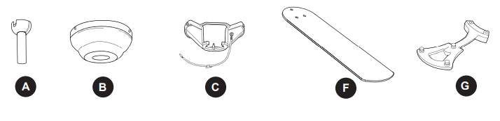
HARDWARE CONTENTS (shown actual size)
PREPARATION
Before beginning assembly of product, make sure all parts are present. Compare parts with package contents list and hardware contents list. If any part is missing or damaged, do not attempt to install, operate or assemble the product.
Estimated Assembly Time: 120 minutes
Tools Required for Assembly (not included): Electrical Tape, Phillips Screwdriver, Pliers, Safety Glasses, Stepladder and Wire Strippers
Helpful Tools (not included): AC Tester Light, Tape Measure, Do-It-Yourself Wiring Handbook and Wire Cutters
INITIAL INSTALLATION
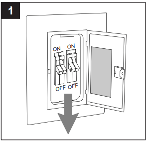
1.Turn off circuit breakers and wall switch to the fan supply line leads.
DANGER: Failure to disconnect power supply prior to installation may result in serious injury or death.
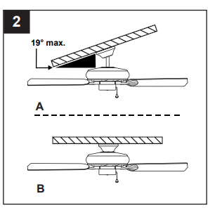
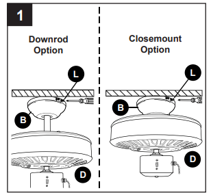
2.Determine mounting method to use.
A. Downrod-style mount (standard or angled ceiling)
B. Closemount-style (standard ceiling only)
IMPORTANT: If using the angle mount, check to make sure the ceiling angle is not steeper than 19°.
*Helpful Hint: Downrod-style mounting is best suited for ceilings 8 ft. or higher. For taller ceilings you may want to use a longer downrod (not included). Angle-style mounting is best suited for angled or vaulted ceilings. A longer downrod is sometimes necessary to ensure proper blade clearance.
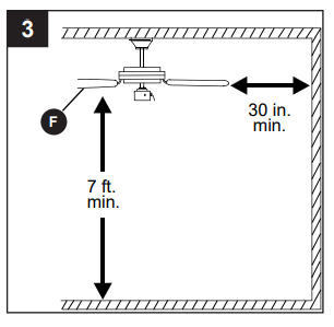
3.Check to make sure blades (F) are at least 30 in. from any obstruction and at least 7 ft. above the floor.
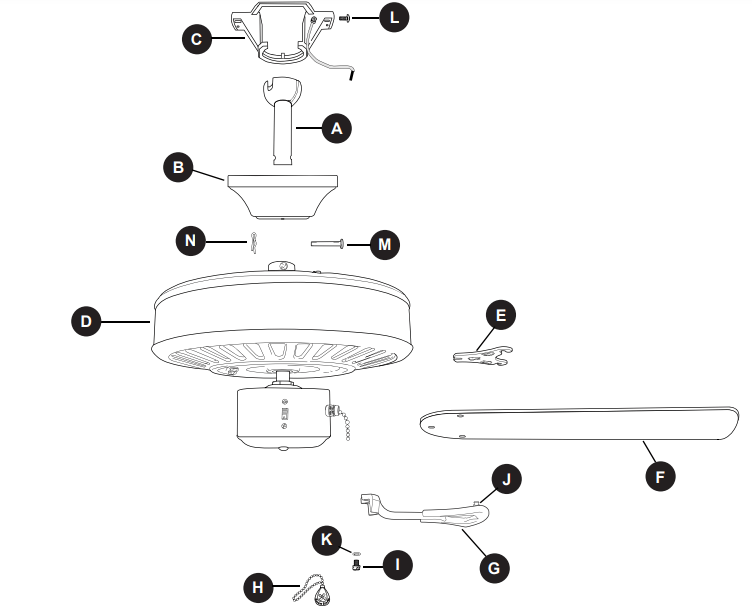
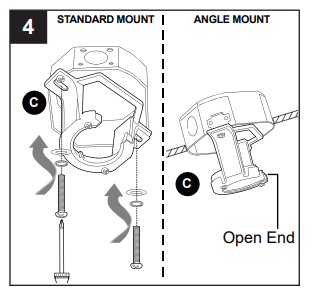
4. Secure mounting bracket (C) to outlet box (not included) using screws, spring washers and flat washers provided with the outlet box.
*NOTE: It is very important you use the proper hardware when installing the mounting bracket (C) as this will support the fan.
IMPORTANT: If using the angle mount, make sure open end of mounting bracket (C) is installed facing the higher point of the ceiling, and ensure the ceiling angle is not steeper than 19°.
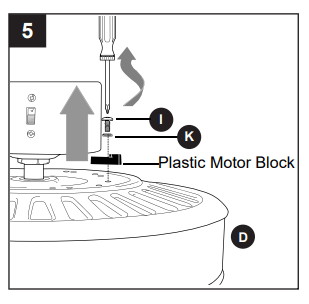
5. Remove motor screws (I) and lock washers (K) from underside of motor housing (D). [If there are plastic motor blocks installed with the motor screws (I) and lock washers (K), discard the plastic motor blocks.]
For DOWNROD-STYLE FAN MOUNTING, proceed to step 1 below. For CLOSEMOUNT-STYLE FAN MOUNTING, skip to page 9.
DOWNROD-STYLE FAN MOUNTING
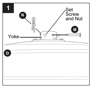
1. Remove pin (M) and clip (N) from yoke at top of motor housing (D) and partially loosen preassembled set screws and nuts.
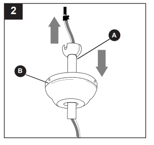
2. Insert downrod (A) through canopy (B). Thread wires from motor housing (D) up through downrod (A).
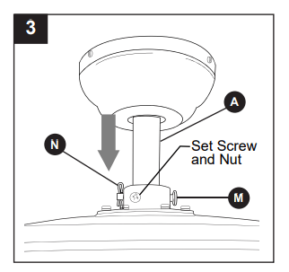
3. Slip downrod (A) into yoke, align holes and re-install pin (M) and clip (N). Tighten set screws in yoke and then tighten nuts on the set screws.
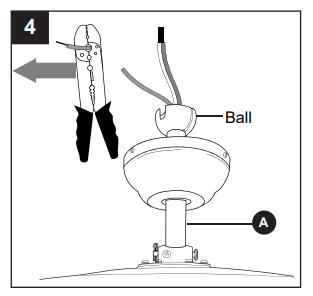
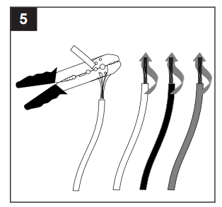
4. Depending on the length of downrod you use, you may need to cut the lead wires back to simplify the wiring. If you decide to cut back the lead wires, it is suggested you do so in the following manner:
Take the lead wires and make sure you have pulled them all the way through the top of the downrod. Start at the TOP of the ball on the downrod and measure 8 in. of lead wire, and then cut the excess wire off with wire cutters (not included).
NOTE: If you do not cut back the lead wires, Steps 4 and 5 are not necessary and you may proceed to Step 6 instead.
5. If you decided to cut back the lead wires in Step 4, strip 1/2 in. of insulation from end of white wire. Twist stripped ends of each strand of wire within the insulation with pliers (not included). Repeat Step 5 for black, blue (if applicable) and green wires.
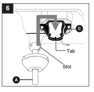
6. Install ball end of downrod (A) into opening of mounting bracket (C). Align slot in ball with tab in mounting bracket (C).
DANGER: Failure to align slot in ball with tab may cause the fan to wobble or fall, which could result in serious injury or death.
Continue to WIRING.
CLOSEMOUNT-STYLE FAN MOUNTING
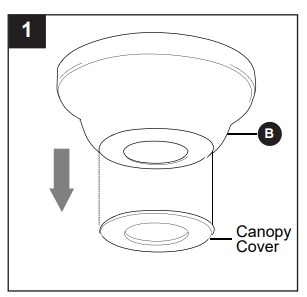
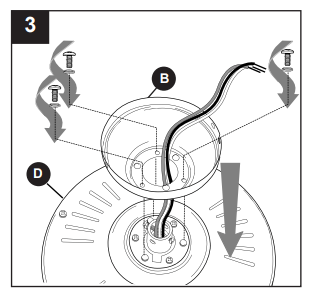
1. Remove canopy cover from bottom of canopy (B). [NOTE: It may be necessary to use the handle end of a screwdriver (not included) to remove the canopy cover by tapping on the canopy cover from the inside of the canopy (B).]
NOTE: Closemount-style mounting is more suitable for ceilings lower than 8 ft. high. The downrod (A), canopy cover, pin and clip are not used in this type of installation.
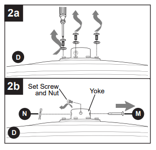
2a. Remove every other screw and lock washer from top of motor housing (D).
2b. Remove pin (M), clip (N) and preassembled set screws and nuts from yoke on motor housing (D). They are not needed for this installation type.
3. Pull wires up through hole in the middle of the canopy (B) and attach canopy (B) to motor housing (D) using the three screws and three lock washers previously removed.
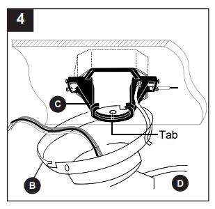
4. Temporarily hang fan on the tab on the mounting bracket (C) using one of the non-slotted holes in the canopy (B).
WIRING
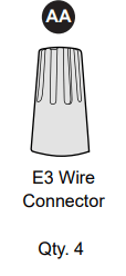
WARNING: To reduce the risk of fire, electrical shock, or personal injury, wire connectors provided with this fan are designed to accept only one 12-gauge house wire and two lead wires from the fan. If your house wire is larger than 12-gauge or there is more than one house wire to connect to the corresponding fan lead wires, consult an electrician for the proper size wire connectors to use.
CAUTION: Be sure outlet box is properly grounded and that a ground (green or bare) wire is present.
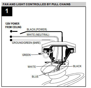
WARNING: If house wires are different colors than referred to in the following steps, stop immediately. A professional electrician is recommended to determine wiring. For each wire connection below, use one of the wire connectors (AA) provided, making sure to screw wire connector (AA) on in a clockwise direction. Connect BLACK and BLUE wire from fan to BLACK wire from ceiling. Connect WHITE wire from fan to WHITE wire from ceiling. Connect GREEN wire from fan (on downrod (A) and mounting bracket (C)) to BARE/GREEN wire from ceiling.
NOTE: This fan is remote control adaptable (remote control not included). Please refer to instructions provided with the remote control before proceeding with these wiring instructions.
1. For each wire connection below, use one of the wire connectors (AA) provided, making sure to screw wire connector (AA) on in a clockwise direction. Connect BLACK and BLUE wire from fan to BLACK wire from ceiling.
Connect WHITE wire from fan to WHITE wire from ceiling. Connect GREEN wire from fan (on downrod (A) and mounting bracket (C)) to BARE/GREEN wire from ceiling.
NOTE: BLACK wire is hot power for fan. BLUE wire is hot power for light kit. WHITE wire is common for fan and light kit. BARE/GREEN wire is ground.
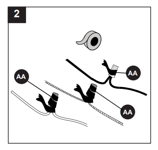
2. Wrap electrical tape (not included) around each individual wire connector (AA) down to the wire.
WARNING: Make sure no bare wire or wire strands are visible after making connections. Place GREEN and WHITE connections on opposite side of box from the BLACK and BLUE (if applicable) connections. Turn spliced/taped wires upward and gently push wires and wire connectors (AA) into outlet box.
Hardware Used
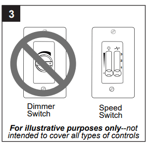
3. IMPORTANT: Using a full range dimmer switch (not included) to control fan speed will cause a loud humming noise from fan. To reduce the risk of fire or electrical shock, do NOT use a full range dimmer switch to control fan speed.
FINAL INSTALLATION
1. Temporarily lift canopy (B) to mounting bracket (C) to determine which two canopy mounting screws (L) in mounting bracket (C) align with slotted holes in canopy (B) and partially loosen these two canopy mounting screws (L). Remove the other two canopy mounting screws (L). Now, lift canopy (B) to mounting bracket (C) again, aligning slotted holes in canopy (B) with loosened canopy mounting screws (L) in mounting bracket (C). Twist canopy (B) clockwise to lock. Re-insert the two canopy mounting screws (L) that were just removed and tighten all canopy mounting screws (L) securely.
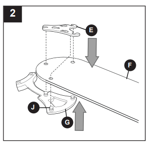
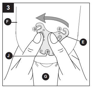
2. Align the three blade screws (J), pre-installed on one blade arm (G), with the three holes in one blade (F). Press up on the blade arm (G) firmly so the blade screws (J) come through the holes in the blade (F). Be careful not to use so much force that the blade arm (G) bends.
3. Note label on plastic locking mechanism (E) indicating THIS SIDE UP. Place the plastic locking mechanism (E) on the opposite side of the blade (F) as the blade arm (G), with the narrower end of the plastic locking mechanism (E) toward the end of the blade (F) and against the blade screw (J).
Rotate plastic locking mechanism (E) counterclockwise to lock plastic locking mechanism (E) into place.
Repeat Steps 2 and 3 for each blade arm (G) and blade (F).
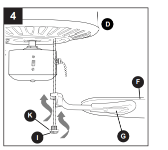
4. Locate motor screws (I) and lock washers (K) previously removed (Step 5, page 7). Insert two motor screws (I) along with lock washers (K) through one blade arm (G) to attach blade arm (G) to motor. Tighten motor screws (I) securely. Repeat with remaining blade arms (G), making sure to completely secure each blade arm (G) before proceeding with the next.
NOTE: If you purchased a compatible light kit, refer to the instructions provided with the light kit to complete your installation.
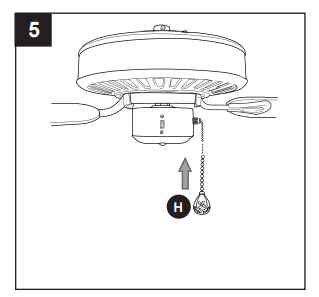
5. Attach pull chain extension (H) or a custom pull chain extension (not included) to the fan pull chain.
OPERATING INSTRUCTIONS
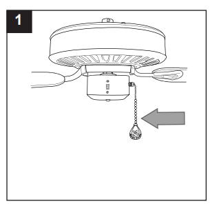
1. The pull chain has four positions to control fan speed. One pull is HIGH, two is MEDIUM, three is LOW and four turns the fan OFF.
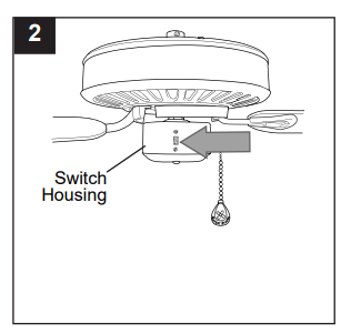
2. Use the fan reverse switch, located on the switch housing, to optimize your fan for seasonal performance. A ceiling fan will allow you to raise your thermostat setting in summer and lower your thermostat setting in winter without feeling a difference in your comfort.
NOTE: Wait for fan to stop before moving the reverse switch.
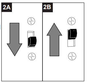
2A. In warmer weather, setting the reverse switch in the DOWN position will result in downward airflow creating a wind chill effect.
2B. In cooler weather, setting the reverse switch in the UP position will result in upward airflow that can help move stagnant, hot air off the ceiling area.
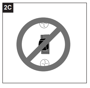
2C. IMPORTANT: Reverse switch must be set either completely UP or completely DOWN for fan to function. If the reverse switch is set in the middle position, fan will not operate.
CARE AND MAINTENANCE
At least twice each year, lower canopy (B) to check downrod (A) assembly, and then tighten all screws on the fan. Clean motor housing (D) with only a soft brush or lint-free cloth to avoid scratching the finish. Clean blades (F) with a lint-free cloth. You may occasionally apply a light coat of furniture polish to wood blades for added protection.
IMPORTANT: Shut off main power supply before beginning any maintenance. Do not use water or a damp cloth to clean the ceiling fan.
TROUBLESHOOTING
WARNING: Before beginning work, shut off the power supply to avoid electrical shock.
PROBLEM
POSSIBLE CAUSE
CORRECTIVE ACTION
Fan does not move.
1. Reverse switch not engaged.
2. Power is off or fuse is blown.
3. Faulty wire connection.
1. Push switch firmly either up or down.
2. Turn power on or check fuse.
3. Turn power off. Loosen canopy and check all connections.
Noisy operation
1. Blades are loose.
2. Cracked blade.
3. Full range dimmer switch.
4. Fan is new.
1. Check to be sure plastic locking mechanisms are secure.
2. Replace blade.
3. Replace with an approved speed control device.
4. Allow fan a “break in” period of a few days, especially when running the fan at Medium and High speeds.
Excessive wobbling
1. Blades are loose.
2. Blade arms incorrectly attached.
3. Unbalanced blades.
4. Fan not securely mounted.
5. Fan too close to vaulted ceiling.
6. Set screw(s) on motor housing yoke is (are) not tightened properly.
7. Set screw on hanging ball is not tightened properly.
1. Check to be sure plastic locking mechanisms are secure.
2. Re-install blade arms.
3. Switch one blade with a blade from the opposite side.
4. Turn power off. Carefully loosen canopy and verify that mounting bracket is secure.
5. Use a longer downrod or move fan to another location.
6. Tighten yoke set screw(s) securely.
7. Carefully loosen and lower canopy and verify that set screw on hanging ball is tightened securely.
NOTE: A small amount of "wobble" is normal and should not be considered a defect.
LIMITED LIFETIME WARRANTY
The distributor warrants this fan to be free from defects in workmanship and materials present at time of shipment from the factory for Lifetime limited from the date of purchase. This warranty applies only to the original purchaser. The distributor agrees to correct any defect at no charge or, at our option, replace the ceiling fan with a comparable or superior model.
To obtain warranty service, present a copy of your sales receipt as proof of purchase. All cost of removal and reinstallation are the express responsibility of the purchaser. Any damage to the ceiling fan by accident, misuse or improper installation, or by using parts not produced by the manufacturer of this fan or affixing accessories not produced by the manufacturer of this fan, are the purchaser's own responsibility. The distributor assumes no responsibility whatsoever for fan installation during the limited lifetime warranty. Any service performed by an unauthorized person will render the warranty invalid.
Due to varying climatic conditions, this warranty does not cover changes in brass finish, rusting, pitting, tarnishing, corroding or peeling. Brass finish fans maintain their beauty when protected from varying weather conditions. Any glass provided with this fan is not covered by the warranty.
Any replacement of defective parts for the ceiling fan must be reported within the first year from the date of purchase. For the balance of the warranty, call our customer service department (at 1-800-643-0067) for return authorization and shipping instructions so that we may repair or replace the ceiling fan. Any fan or parts returned improperly packaged is/are the sole responsibility of the purchaser. There is no further express warranty. The distributor disclaims any and all implied warranties. The duration of any implied warranty which cannot be disclaimed is limited to the limited lifetime period as specified in our warranty. The distributor shall not be liable for incidental, consequential or special damages arising at or in connection with product use or performance except as may otherwise be accorded by law. This warranty gives you specific legal rights and you may also have other rights which vary from state to state. This warranty supersedes all prior warranties.
REPLACEMENT PARTS LIST
For replacement parts, call our customer service department at 1-800-643-0067, 8 a.m. - 6 p.m., EST, Monday - Thursday, 8 a.m. - 5 p.m., EST, Friday