WARNING: To reduce the risk of fire, electrical shock or personal injury, wire connectors provided with this fan are designed to accept only one 12-gauge house wire and two lead wires from the fan. If your house wire is larger than 12-gauge and there is more than one house wire to connect to the two fan lead wires, consult an electrician for the proper size wire connectors to use.
CAUTION: Be sure the outlet box is properly grounded or that a ground (green or bare) wire is present
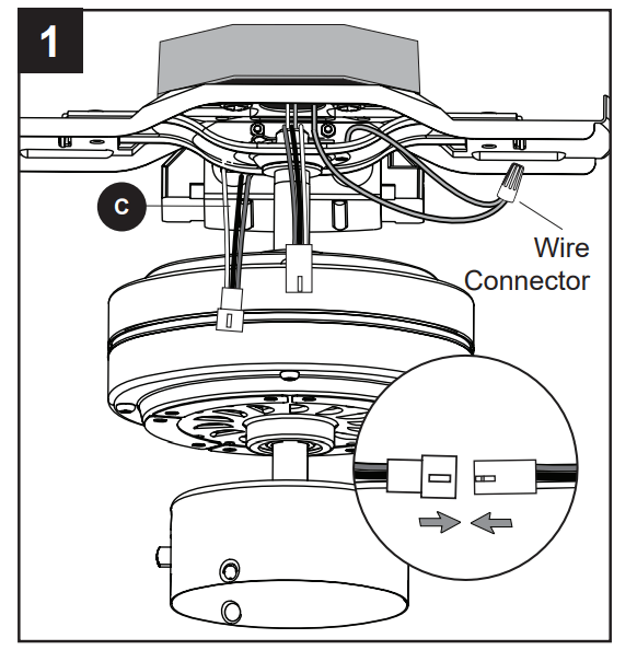
Connect the remaining wires from the receiver (C), fan and house supply according to the diagram and these steps:
Connect the green wire from the fan to the bare/ green (ground) house supply wire using a wire connector from remote pack (O).
Connect the wire harness from the receiver (C) to the wire harness from the fan.
Note: The green wire is the ground. If house wires are different colors than referred to above, it is recommended a professional electrician determines the proper wiring
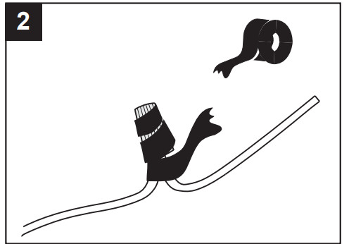
2. Wrap electrical tape around each individual wire connector from remote pack (O), down to the wire.
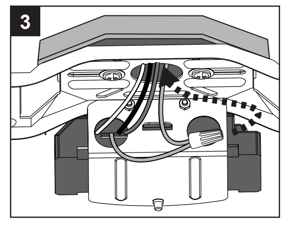
3. Turn the spliced/taped wires upward and gently push the wires and wire connectors into the outlet box. Then insert the connected wire harnesses in the space between the upper mounting bracket and the lower mounting bracket.
WARNING: Ensure no bare wire or wire strands are visible after making connections. Place the green and white wire connections on the opposite side of the outlet box from the black.
FINAL INSTALLATION
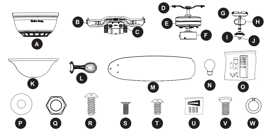
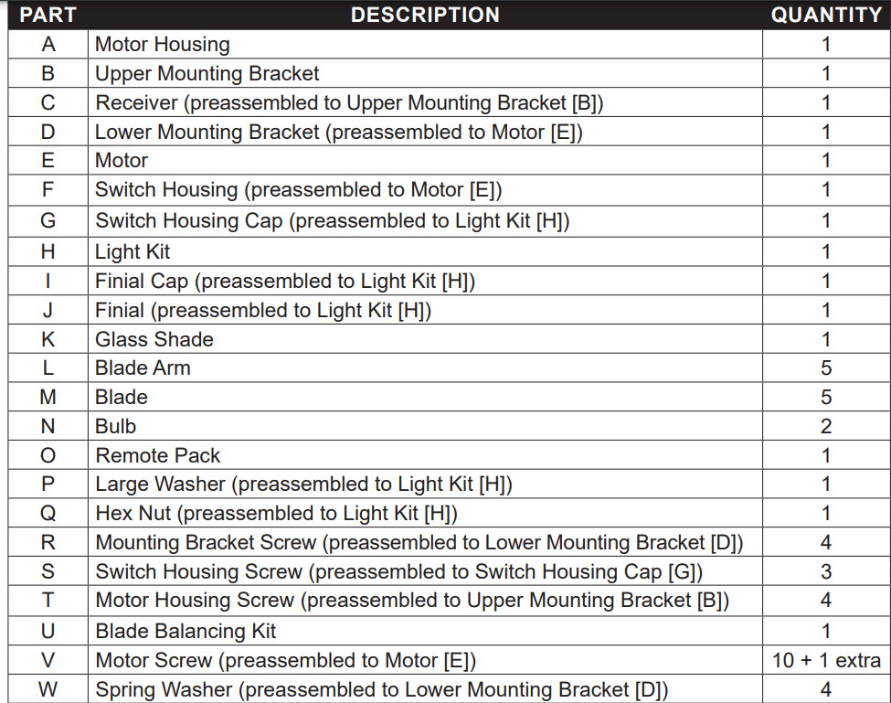
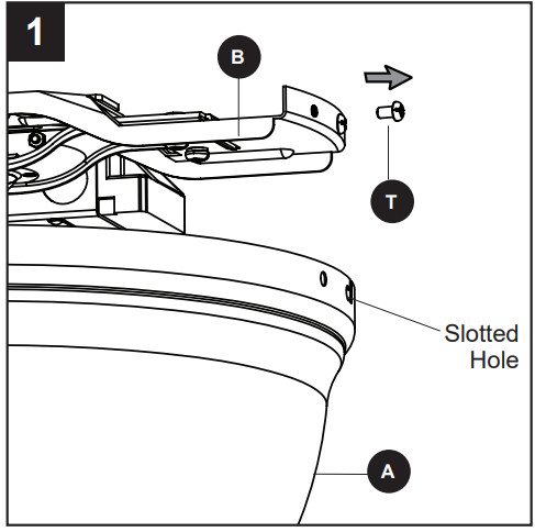
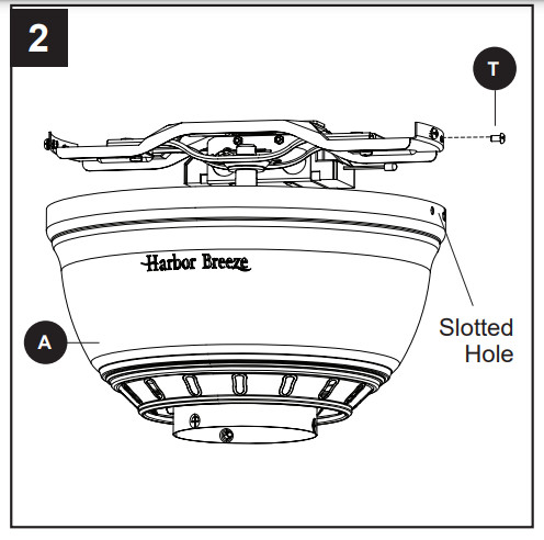
1. Temporarily lift the motor housing (A) to the upper mounting bracket (B) to determine which two motor housing screws (T) in the sides of the upper mounting bracket (B) align with the slotted holes in the top edge of the motor housing (A). Partially loosen the two motor housing screws (T) that align with the slotted holes. Remove the other two motor housing screws (T) from the upper mounting bracket (B)
2. Slide the motor housing (A) over the motor (E), aligning the slotted holes in the motor housing (A) with the loosened motor housing screws (T) in the upper mounting bracket (B). Twist the motor housing (A) to lock. Then re-insert the two previously removed motor housing screws (T) and securely tighten all screws.
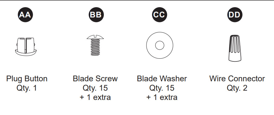
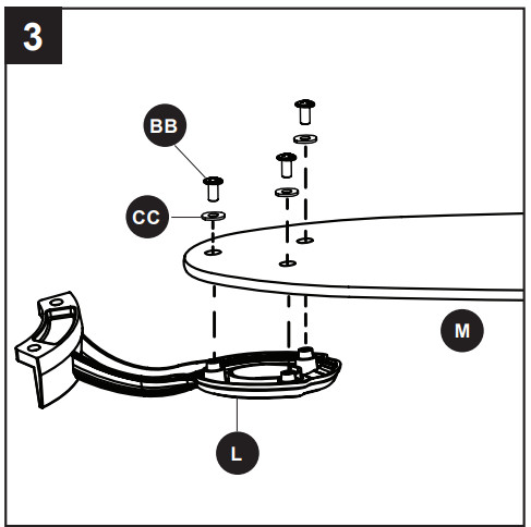
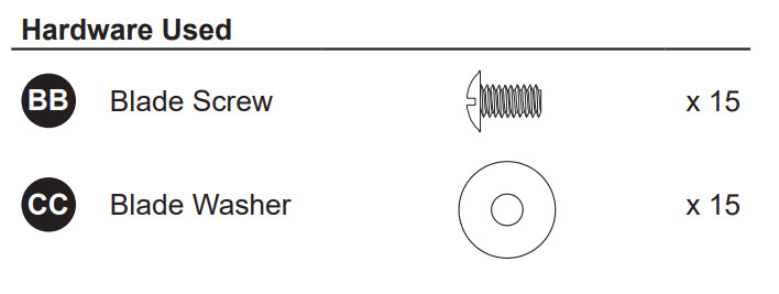
3. Partially insert the blade screws (BB) along with the blade washers (CC) through the blade (M) and into the blade arm (L). Tighten each blade screw (BB) with a Phillips screwdriver (not included), starting with the one in the middle. Repeat this step for the remaining blades (M) and blade arms (L).
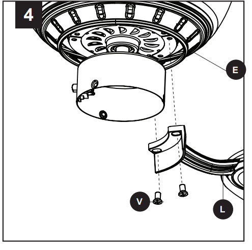
4. Install the blade arm (L) to the underside of the motor (E) with motor screws (V) previously removed (Step 7, page 9). Tighten with Phillips screwdriver. Repeat for each blade arm (L).
Note If you wish to install the fan without the light kit, proceed to Step 10.
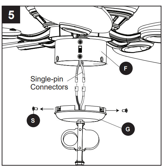
5. To install the light kit, first remove the switch housing screws (S) preassembled to the switch housing cap (G). Then, connect the single-pin connectors from the switch housing (F) and switch housing cap (G) -- blue to black and white to white.
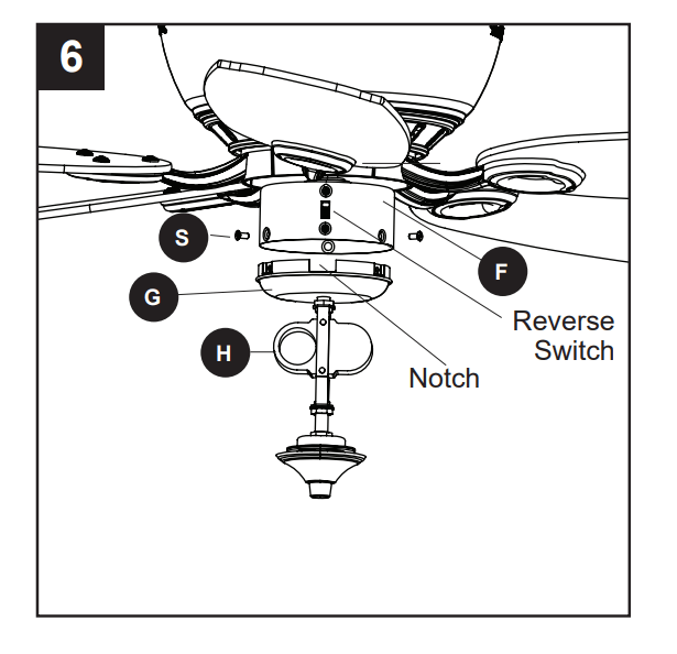
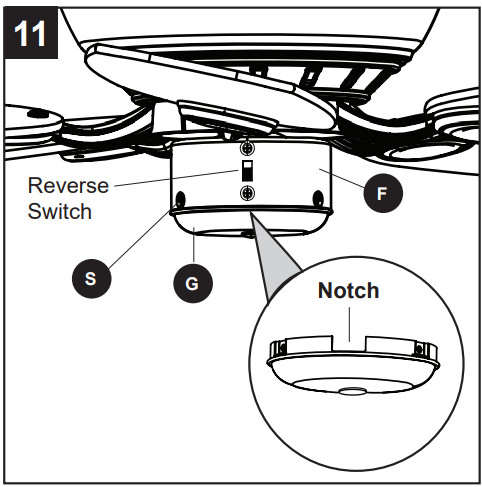
6. Align the notch in the switch housing cap (G) with the reverse switch located on switch housing (F). Then assemble the switch housing cap (G) with light kit (H) to the switch housing (F) using the previously removed switch housing screws (S).
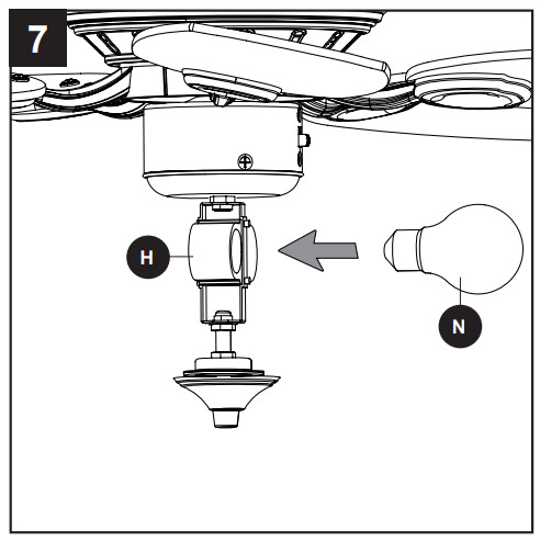
7. Install bulbs (N) into the sockets on the light kit (H).
Important Make sure you allow the bulbs (N) and light kit (H) to cool before you replace the bulbs.
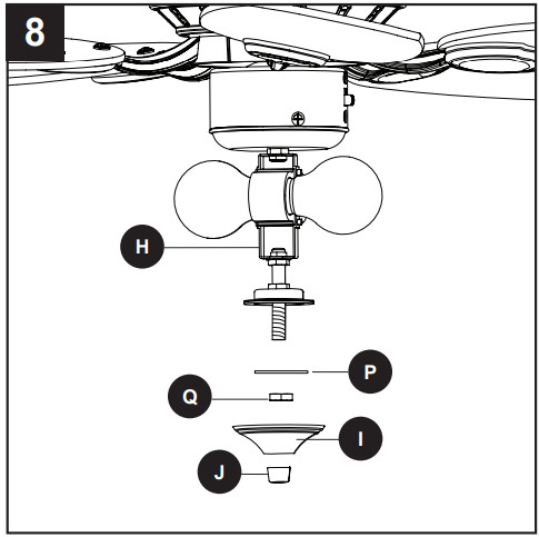
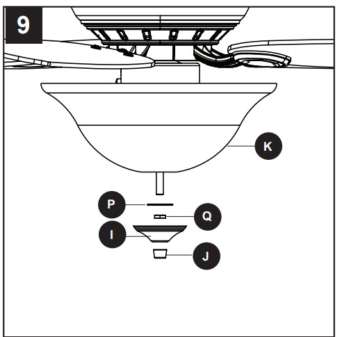
8. Remove the preassembled large washer (P), hex nut (Q), finial cap (I) and finial (J) from the light kit (H)
9. Lift the glass shade (K) onto the threaded rod at the bottom of the light kit (H). Re-install large washer (P) and secure with hex nut (Q). Lift the finial cap (I) onto the threaded rod and then screw the finial (J) onto the threaded rod to secure.
Proceed to Step 12.
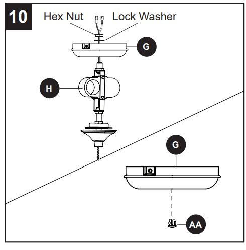
10. To install the fan without the light kit (H), remove the hex nut and lock washer from the rod on the inside of the switch housing cap (G). Remove light kit (H) from the switch housing cap (G) and discard, then install the plug button (AA) into the center hole of the switch housing cap (G).
11. Remove the three switch housing screws (S) from the switch housing cap (G) and install the switch housing cap (G) onto the switch housing (F). Align the notch in the switch housing cap (G) with the reverse switch located on switch housing (F), then re-install the three switch housing screws (S).
12. Turn on the power supply.
Assembly is complete.
OPERATING INSTRUCTIONS
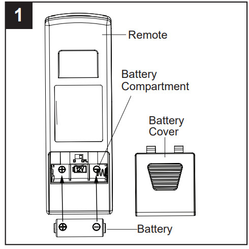
1. Remove the battery cover from the back of the remote found in remote pack (O). Insert the battery from remote pack (O) into the remote; ensure polarity of battery matches the polarity indicated in the battery compartment -- positive (+) to positive (+) and negative (-) to negative (-). Replace the battery cover and press the fan power button on the remote to ensure the LED indicator illuminates and the remote turns on the fan.
Note: If remote doesn’t turn on the fan, see TROUBLESHOOTING (page 17).
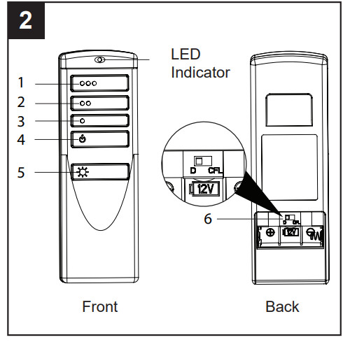
2. To operate the fan using the remote, press and release the following buttons:
1 - High fan speed
2 - Medium fan speed
3 - Low fan speed
4 - Fan Power - Turns the fan off.
Light Delay Off mode - Press and hold the fan power button (4) for five seconds, which will turn off light after one minute. The LED indicator on the remote will flash four times to confirm mode setting
5 - Light Control:
Incandescent Bulbs - Press light control to turn lights off and on. Press and hold light control to dim or brighten the lights. CFL Bulbs -Turns the lights on and off. Note: The dimmer function does not work with CFL bulbs.
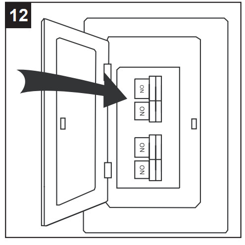
6 - D/CFL Switch: Switch should be set to “D” to correspond with the included LED, which will enable the dimming function. Flip to “CFL” if you change to corresponding bulbs.
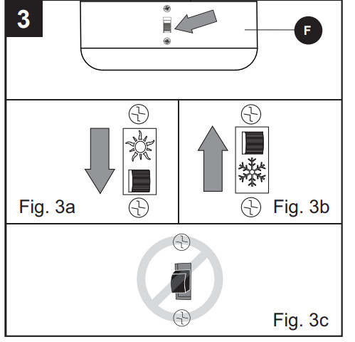
3. Using a ceiling fan will allow you to raise your thermostat setting in summer and lower your thermostat setting in winter without feeling a difference in your comfort. Note: Wait for the fan to stop before moving the reverse switch located on switch housing (F). In warmer weather, push the reverse switch to the down to display a sun icon, which will result in downward airflow creating a wind chill effect (Fig. 3a).
In cooler weather, push the reverse switch to the up to display a snowflake icon, which will result in upward airflow that can help move hot air off the ceiling area (Fig. 3b).
Important The reverse switch must be set either completely up or down in order for the fan to function correctly. If the reverse switch is set in the middle position, the fan will not operate (Fig. 3c)
CARE AND MAINTENANCE
At least twice each year, tighten all screws on the fan. Clean the motor housing with only a soft brush or lint-free cloth to avoid scratching the finish. Bulb Replacement: Use 60-watt max. E26-base LED, CFL or incandescent bulbs. Halogen bulbs are not recommended for this item. Battery Replacement for Remote: Use A23 12-volt battery.
Important Shut off the main power supply before you begin any maintenance tasks. Do not use water or a damp cloth to clean the ceiling fan.
TROUBLESHOOTING
PROBLEM
POSSIBLE CAUSE
CORRECTIVE ACTION
The fan does not move.
The power is off or the fuse is blown.
There is a faulty wire connection.
The plugs are not connected properly.
The reverse switch is not completely engaged.
Turn the power on or check the fuse.
Turn the power off. Loosen the canopy and check all connections.
Check that the connectors from the light kit and fan are connected properly.
Push the reverse switch completely to the left or right.
There is excessive wobbling.
The blades and/or blade arms are loose.
The blades are unbalanced.
The fan mounting is not secure.
Check and tighten all screws that hold the fan blades to the blade arms and the blade arms to the motor.
Switch one blade with a blade from the opposite side. Or balance the fan using the blade balancing kit (U).
Turn off the power. Loosen the motor housing and verify the upper mounting bracket is secure to the electrical outlet box. The bracket must be flush without movement against the outlet box.
The fan operates correctly, but the lights are not working.
The bulbs are not installed correctly.
The light kit wire plugs are not connected properly.
There is a faulty wire connection.
Re-install the bulb(s).
Ensure the single-pin connectors in the light kit are connected properly.
Turn the power off and check all connections at the ceiling outlet box.
The fan is noisy.
The blades are loose.
There is a cracked blade.
The outlet box is not secure.
The mounting bracket is not secure.
Check and tighten all screws that hold the fan blades to the blade arms and the motor.
Replace the cracked blade.
Ensure the outlet box is secured to the building structure.
Ensure the mounting bracket is secured to the outlet box and that the screws are tight.
Remote doesn’t work.
LED indicator does not illuminate when remote button is pushed.
The remote control is not synced with the fan’s receiver.
Replace the transmitter battery with a new 12-volt battery.
Turn off the main power, then turn it back on. Within 30 seconds, press and hold the high and low speed buttons on the remote at the same time for 5 seconds. Once complete, the fan will start on the low speed with the light (if applicable) off.