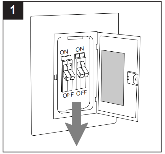
Turn off circuit breakers and wall switch to the fan supply line leads.
DANGER: Failure to disconnect power supply prior to installation may result in serious injury or death.
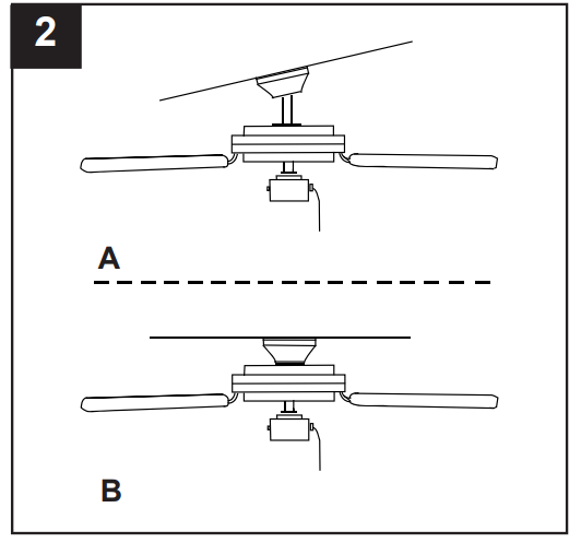
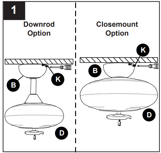
2. Determine mounting method to use.
A. Downrod mount (standard or angled ceiling)
B. Closemount (standard ceiling only)
IMPORTANT: If using the angle mount, check to make sure the ceiling angle is not steeper than 19°.
*Helpful Hint: Downrod-style mounting is best suited for ceilings 8 ft. or higher. For taller ceilings you may want to use a longer downrod (not included). Angle-style mounting is best suited for angled or vaulted ceilings. A longer downrod is sometimes necessary to ensure proper blade clearance.
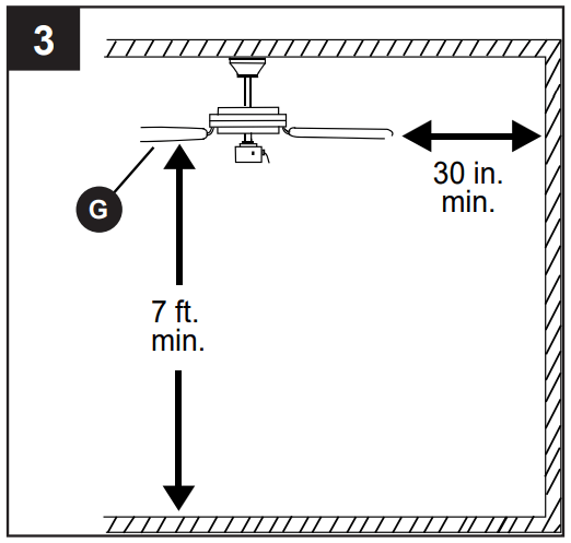
3. Check to make sure blades (G) will be at least 30 inches from any obstruction and at least 7 ft. above the floor.
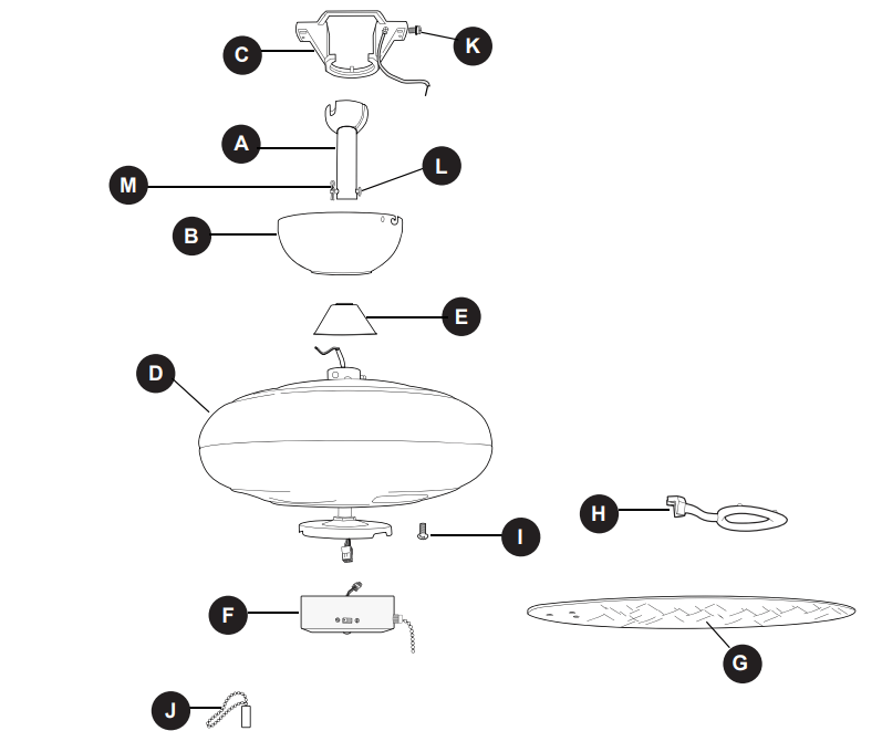
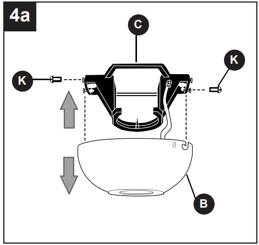
4a. Loosen canopy mounting screws (K) in slotted holes in canopy (B) and remove the other two canopy mounting screws (K) -- save canopy mounting screws (K) for later use. Remove mounting bracket (C) from canopy (B).
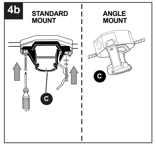
4b. Secure mounting bracket (C) to outlet box (not included) using screws, spring washers and flat washers provided with the outlet box.
*NOTE: It is very important you use the proper hardware when installing the mounting bracket (C) as this will support the fan.
IMPORTANT: If using angle mount, make sure open end of mounting bracket (C) is installed facing the higher point of the ceiling.
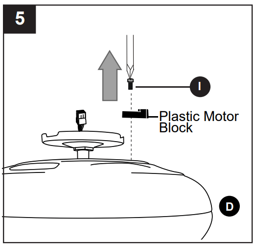
5. Remove motor screws (I) from underside of motor and save for blade arm (H) attachment later on. If there are plastic motor blocks installed with the motor screws (J), discard the plastic motor blocks.
For DOWNROD-STYLE FAN MOUNTING, proceed to step 1 on the next page.
For CLOSEMOUNT-STYLE FAN MOUNTING, skip to page 9.
DOWNROD-STYLE FAN MOUNTING
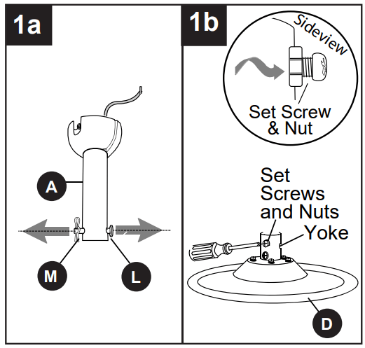
1a. Remove pin (L) and clip (M) from downrod (A).
1b. Partially loosen preassembled set screws and nuts in yoke at top of motor housing (D)
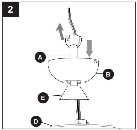
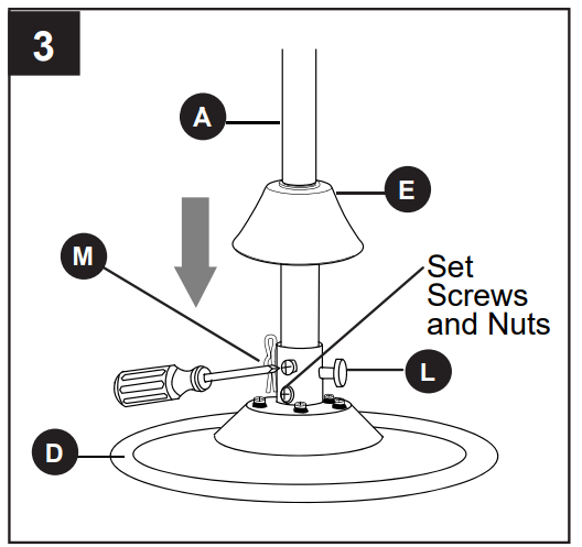
2. Insert downrod (A) through canopy (B) and yoke cover (E). Thread wires from motor housing (D) up through downrod (A).
3. 2. Insert downrod (A) through canopy (B) and yoke cover (E). Thread wires from motor housing (D) up through downrod (A). Slip downrod (A) into yoke, align holes and re-install pin (L) and clip (M). Tighten set screws and then tighten nuts on the set screws. Slide yoke cover (E) down until it rests on top of motor housing (D).
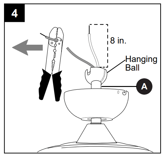
4. Depending on the length of downrod you use, you may need to cut the lead wires back to simplify the wiring. If you decide to cut back the lead wires, it is suggested you do so in the following manner:
Take the lead wires and make sure you have pulled them all the way through the top of the downrod (A). Start at the TOP of the hanging ball on the downrod (A) and measure 8 in. of lead wire, then cut the excess wire off with wire cutters (not included).
NOTE: If you do not cut back the lead wires, Steps 4 and 5 are not necessary and you may proceed to Step 6 instead.
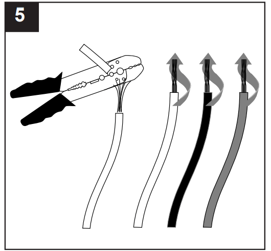
5. If you decided to cut back the lead wires in Step 4, strip 1/2 in. of insulation from end of each wire -- white, black, green and blue (if applicable). Twist stripped ends of each strand of wire within the insulation with pliers (not included).
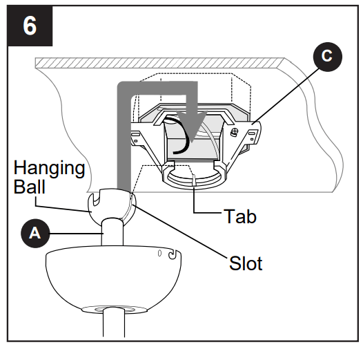
6. Install hanging ball of downrod (A) into opening of mounting bracket (C). Align one of the slots in hanging ball with tab in mounting bracket (C).
CLOSEMOUNT-STYLE FAN MOUNTING
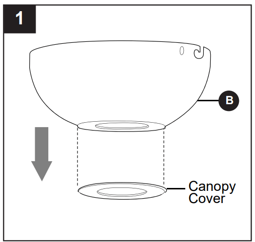
Remove canopy cover from bottom of canopy (B).
NOTE: It may be necessary to use the handle end of a screwdriver (not included) to remove the canopy cover by tapping on the canopy cover from the inside of the canopy (B).
NOTE: Downrod (A), yoke cover (E) and canopy cover are not used in this type of installation.
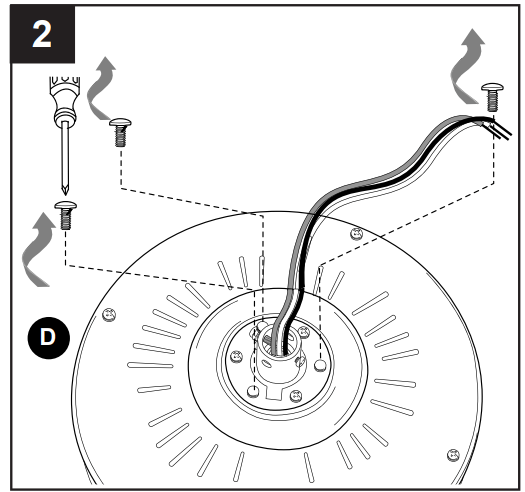
2. Remove every other preassembled screw from top of motor housing (D).
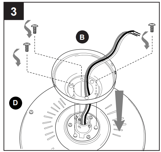
3. Pull wires up through hole in the middle of the canopy (B) and attach canopy (B) to motor housing (D) using the three screws previously removed.
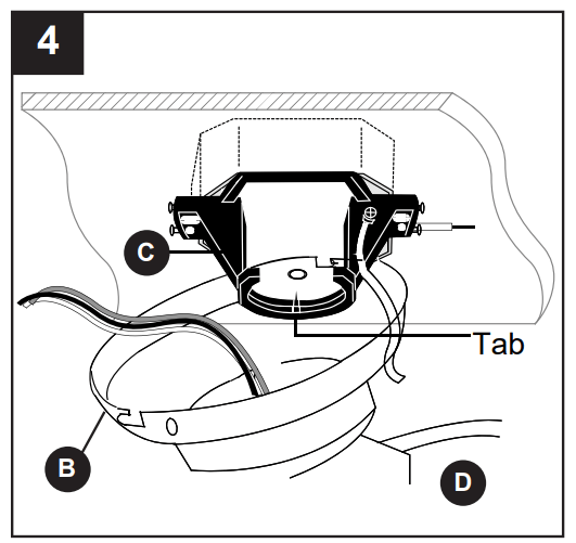
4. Temporarily hang fan on the tab on the mounting bracket (C) using one of the non-slotted holes in the canopy (B).
WIRING
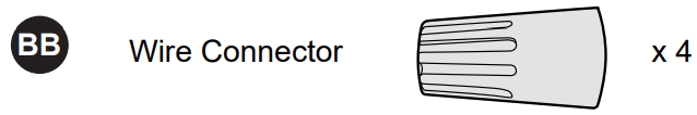
Choose wiring diagram (Fig. 1a, Fig. 1b or Fig. 1c) that fits your situation and make appropriate wiring connections as follows: [IMPORTANT: For each wire connection below, use one of the wire connectors (BB) provided, making sure to screw wire connector (BB) on in a clockwise direction.]
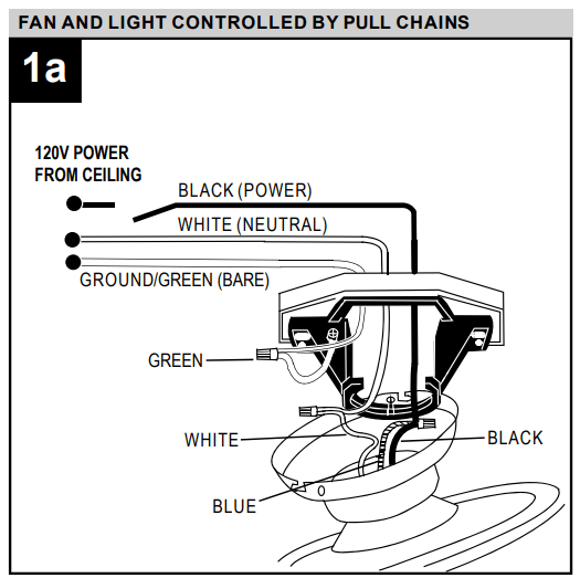
1a. FAN AND LIGHT CONTROLLED BY PULL CHAINS: Connect BLACK and BLUE wire from fan to BLACK wire from ceiling. Connect WHITE wire from fan to WHITE wire from ceiling. Connect all GROUND (GREEN) wires together from fan (on downrod (A) and mounting bracket (C)) to BARE/GREEN wire from ceiling.
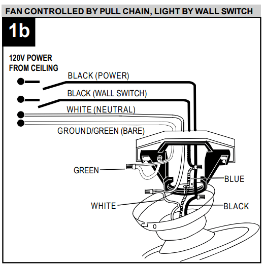
1b. FAN CONTROLLED BY PULL CHAIN, LIGHT BY WALL SWITCH: If you intend to control the fan light with a separate wall switch, connect BLACK wire from fan to BLACK wire from ceiling. Connect BLUE wire from fan to the BLACK wire from the independent wall switch for the light. Connect WHITE wire from fan to WHITE wire from ceiling. Connect all GROUND (GREEN) wires together from fan (on downrod (A) and mounting bracket (C)) to BARE/GREEN wire from ceiling.
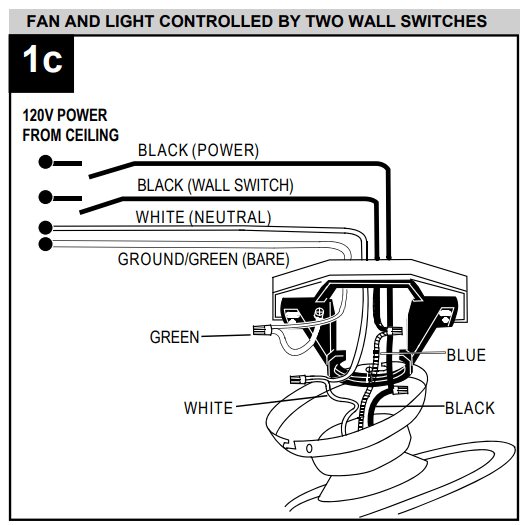
1c. FAN AND LIGHT CONTROLLED BY TWO WALL SWITCHES: If you intend to control the fan and light with separate wall switches, connect BLACK wire from fan to BLACK wire from the independent wall switch for the fan. Connect BLUE wire from fan to the BLACK wire from the other independent wall switch for the light. Connect WHITE wire from fan to WHITE wire from ceiling. Connect all GROUND (GREEN) wires together from fan (on downrod (A) and mounting bracket (C)) to BARE/GREEN wire from ceiling.
NOTE: BLACK wire is hot power for fan. BLUE wire is hot power for light kit. WHITE wire is common for fan and light kit. BARE/GREEN wire is ground.
Hardware Used
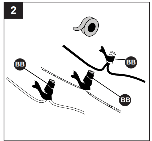
2. Wrap electrical tape (not included) around each individual wire connector (BB) down to the wire.
WARNING: Make sure no bare wire or wire strands are visible after making connections. Place green and white connections on opposite side of box from the black and blue (if applicable) connections.
Turn spliced/taped wires upward and gently push wires and wire connectors (BB) into outlet box.
FINAL INSTALLATION
Lift canopy (B) to mounting bracket (C) and align slotted holes in canopy (B) with canopy mounting screws (K) loosened in Step 4a, page 6. Twist canopy (B) clockwise to lock. Re-insert the two canopy mounting screws (K) previously removed (Step 4a, page 6), then tighten all securely.
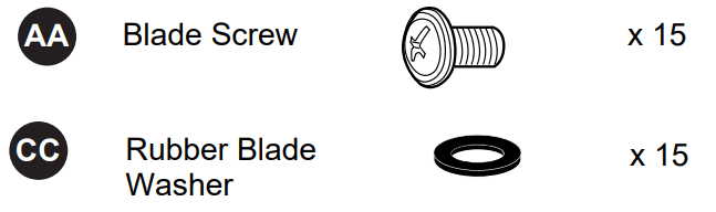
2. Align posts in blade arm (H) with holes on ridged side of blade (G) and then push up on blade arm (H) until posts go through the holes in blade (G). Insert three blade screws (AA), along with three rubber blade washers (CC), to attach blade arm (H) to blade (G). Then, tighten each blade screw (AA) starting with the one in the middle. Repeat with remaining blades (G).
Hardware Used
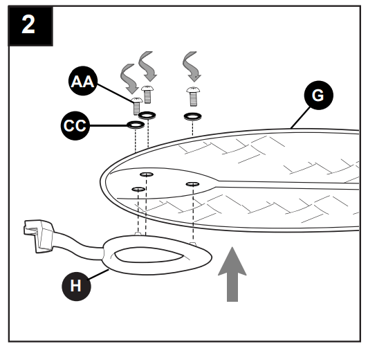
3. Attach blade arms (H) to the bottom of motor housing (D) with motor screws (I) previously removed (Step 5, page 7). Tighten motor screws (I) securely.
Note: Make sure to completely secure each blade arm (H) before proceeding to the next.
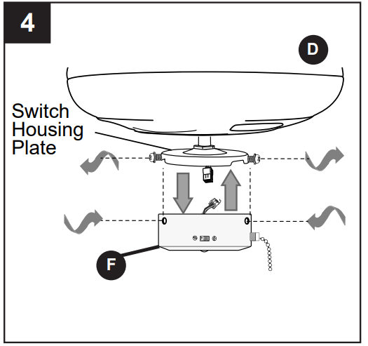
4. Remove three preassembled screws from switch housing plate on the underside of motor housing (D). Connect male plug from motor housing (D) to female plug from switch housing (F), matching up the colors on the male plug with the colors on the female plug for correct fit. Make sure plugs are connected completely. Align holes in switch housing (F) with holes in switch housing plate. Re-insert screws just removed. Tighten all screws securely.
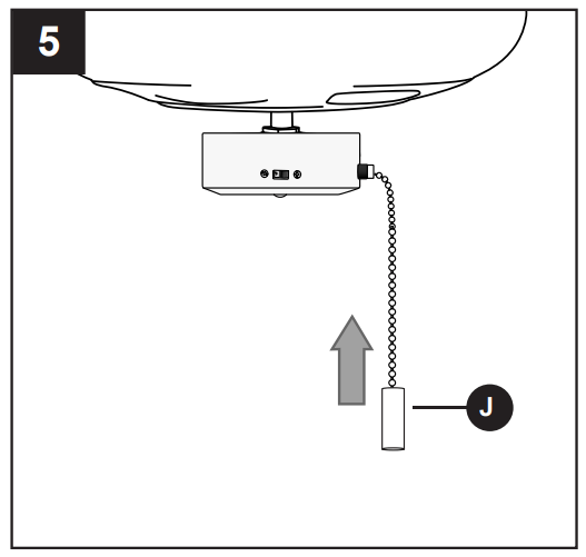
5. Attach pull chain extension (J) or custom pull chain extension (sold separately) to fan pull chain.
OPERATING INSTRUCTIONS
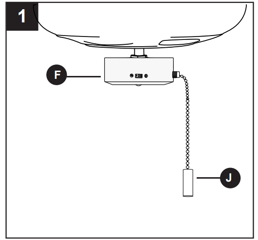
The pull chain located on the switch housing (F) has four positions to control fan speed. One pull is HIGH, two is MEDIUM, three is LOW and four turns the fan OFF.
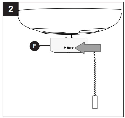
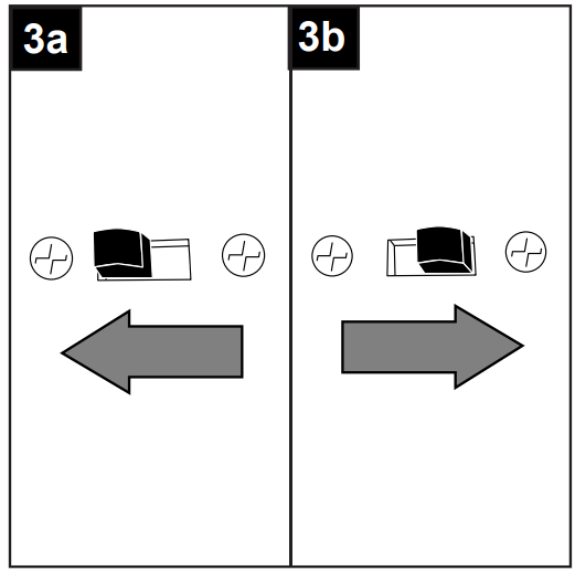
2. Use the fan reverse switch, located on the switch housing (F), to optimize your fan for seasonal performance. A ceiling fan will allow you to raise your thermostat setting in summer and lower your thermostat setting in winter without feeling a difference in your comfort.
NOTE: Wait for fan to stop before moving the reverse switch.
3a. In warmer weather, setting the reverse switch in the LEFT position will result in downward airflow creating a wind chill effect.
3b. In cooler weather, setting the reverse switch in the RIGHT position will result in upward airflow that can help move stagnant, hot air off the ceiling area.
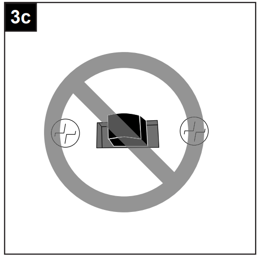
3c. IMPORTANT: Reverse switch must be set either completely LEFT or completely RIGHT for fan to function. If the reverse switch is set in the middle position, fan will not operate
CARE AND MAINTENANCE
At least twice each year, lower canopy (B) to check downrod (A) assembly, and then tighten all screws on fan. Clean motor housing (D) with only a soft brush or lint-free cloth to avoid scratching the finish. Clean blades (G) with a lint-free cloth. You may occasionally apply a light coat of furniture polish to wood blades for added protection.
IMPORTANT: Shut off main power supply before beginning any maintenance. Do not use water or a damp cloth to clean the ceiling fan.
TROUBLESHOOTING
WARNING: Before beginning work, shut off the power supply to avoid electrical shock.
PROBLEM
POSSIBLE CAUSE
CORRECTIVE ACTION
Fan does not move.
1. Reverse switch not engaged.
1. Push switch firmly either up or down.
2. Power is off or fuse is blown.
2. Turn power on or check fuse.
3. Faulty wire connection.
3. Turn power off. Loosen canopy and check all connections.
4. Plugs not connected properly.
4. Check that male and female plugs in switch housing are connected properly according to instructions on page 14.
Noisy operation.
1. Blades are loose.
1. Tighten all blade screws.
2. Cracked blade.
2. Replace blade.
3. Full range dimmer switch.
3. Replace with an approved speed control device.
4. Fan is new.
4. Allow fan a “break in” period of a few days, especially when running the fan at Medium and High speeds.
Excessive wobbling
1. Blades are loose.
1. Tighten all blade screws.
2. Blade arms incorrectly attached.
2. Re-install blade arms.
3. Unbalanced blades.
3. Switch one blade with a blade from the opposite side.
4. Fan not securely mounted.
4. Turn power off. Carefully loosen canopy and verify that mounting bracket is secure.
5. Fan too close to vaulted ceiling.
5. Use a longer downrod or move fan to another location.
6. Set screw(s) on motor housing yoke is (are) not tightened properly.
6. Tighten yoke set screw(s) securely.
7. Set screw on hanging ball is not tightened properly.
7. Carefully loosen and lower canopy and verify that set screw on hanging ball is tightened securely.
NOTE: A small amount of "wobble" is normal and should not be considered a defect.
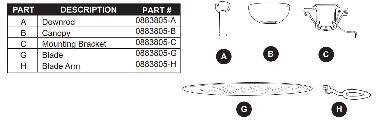
REPLACEMENT PARTS LIST
For replacement parts, call our customer service department at 1-800-643-0067, 8 a.m. - 6 p.m., EST, Monday - Thursday, 8 a.m. - 5 p.m., EST, Friday.