ITEM #0373645
E124404
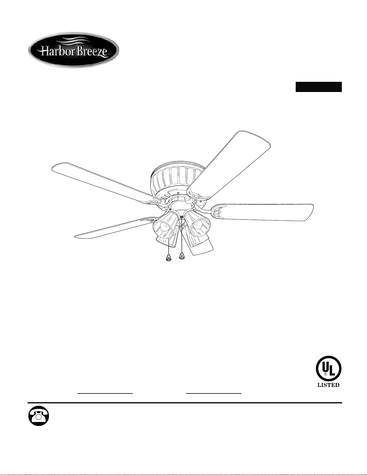
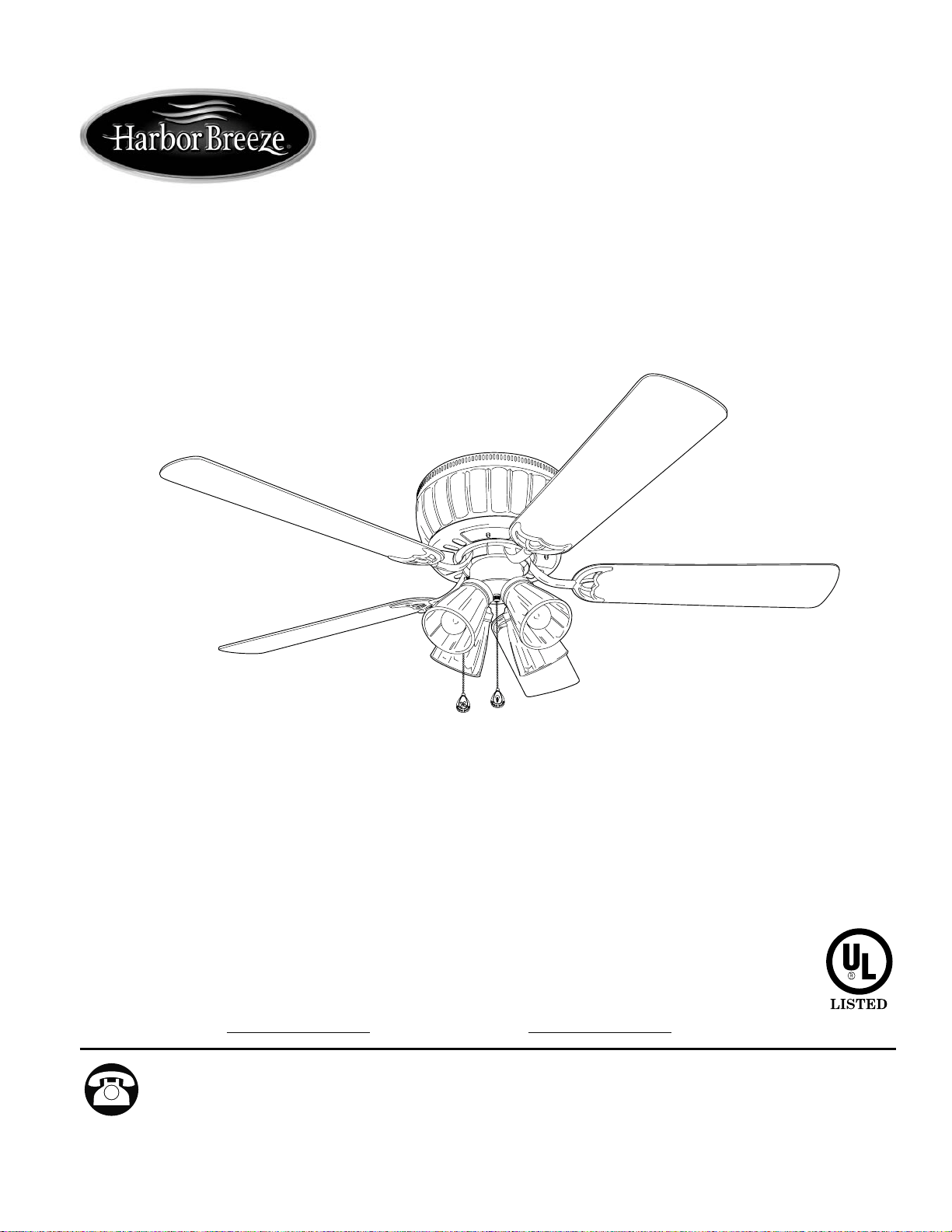
WOLCOTT CEILING FAN
MODEL #WO52BB5C
Questions, problems, missing parts? Before returning to your retailer, call or contact our
customer service department at 1-800-527-1292, 8:30 a.m. - 5:00 p.m., CST, Monday - Friday.
Harbor Breeze® is a registered trademark of
LF, LLC. All Rights Reserved.
Español p. 19
ATTACH YOUR RECEIPT HERE
Serial Number
Purchase Date
1
2
TABLE OF CONTENTS
Safety Information .....................................………………………………………………...…
…..
2 - 3
Package Contents .....……………………………………………………………..….
….
.........
...
4
Hardware Contents ...................................................................................................................
...
5
Preparation ...............….…………………..……………………….…………….………………....5
Initial Installation ............….……………..……………………….……….
…..….
..........................6 - 7
Wiring ...............….…………………..……………………….…………….……………...........7 - 9
Final Installation .....……………………………………………………………..….
….
.....
.
10 - 13
Lighted Housing Bulb Replacement ...........................................................................................14
Operation Instructions ............................................................……………………
……
….
........
14 - 15
Care and Maintenance …
….…
…………………………………………………..….......
.....
..
....
15
Troubleshooting .............………...………………………….……………..………....
…...........
.16
Warranty ……………………………….…………………………………………..…
….
.........
.....
17
Replacement Parts List ...........................................................................................
.........
......
.
........
18
SAFETY INFORMATION
READ AND SAVE THESE INSTRUCTIONS
Please read and understand this entire manual before attempting to assemble, install or operate the
product. If you have any questions regarding the product, please call customer service at
1-800-527-1292, 8:30 a.m. - 5:00 p.m., CST, Monday - Friday.
• Do not discard fan carton or foam inserts. Should this fan need to be returned to the factory for
repairs, it must be shipped in its original packaging to ensure proper protection against damage that
might exceed the initial cause for return.
• Make sure that all electrical connections comply with local codes, ordinances, the National Electrical
Code and ANSI/NFPA 70-1999. Hire a qualified electrician or consult a do-it-yourself wiring handbook,
available at Lowe's, if you are unfamiliar with installing electrical wiring.
• Make sure the installation site you choose allows a minimum clearance of 7 feet from the blades to
the floor and at least 30 in. from the end of the blades to any obstruction.
• After you install the fan, make sure that all connections are secure to prevent the fan from falling.
• The net weight of this fan including the light kit is: 20.5 lbs. (9.3 kg).
3
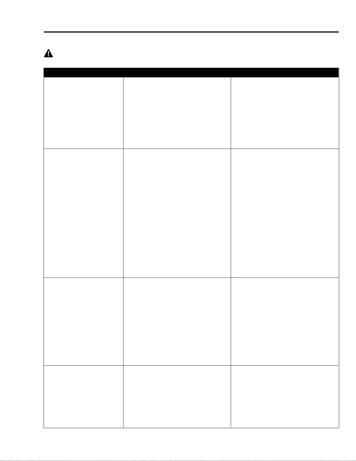
To reduce the risk of fire, electrical shock, or personal injury, mount fan to outlet box
marked "ACCEPTABLE FOR FAN SUPPORT OF 35 LBS (15.9 KG) OR LESS" and use
mounting screws provided with the outlet box. Most outlet boxes commonly used for the
support of lighting fixtures are not acceptable for fan support and may need to be replaced.
Consult a qualified electrician if in doubt.
When mounting fan to a ceiling outlet box, use a METAL octagonal outlet box. Secure the outlet
box directly to the building structure. The outlet box and its support must be able to support the
moving weight of the fan (at least 35 lbs.). Do NOT use a plastic outlet box.
To avoid personal injury, the use of gloves may be necessary while handling fan parts with
sharp edges.
To reduce the risk of fire, electrical shock, or personal injury, wire connectors provided with this
fan are designed to accept only one 12 gauge house wire and two lead wires from the fan. If your
house wire is larger than 12 gauge or there is more than one house wire to connect to the two fan
lead wires, consult an electrician for the proper size wire connectors to use.
To reduce the risk of fire or electrical shock, do not use the fan with any solid state speed
control device or control fan speed with a full range dimmer switch.
To reduce the risk of fire, electrical shock, or personal injury, do not bend the blade arms when
installing them, balancing the blades, or cleaning the fan. Do not insert objects between the
rotating fan blades.
To reduce the risk of personal injury, use only parts provided with this fan. The use of parts
OTHER than those provided with this fan will void the warranty.
WARNINGS
CAUTIONS
Before proceeding, be sure to shut off electricity at main switch or circuit breaker in order to avoid
electrical shock.
Read all instructions and safety information before installing your new fan. Review the
accompanying assembly diagrams.
SAFETY INFORMATION
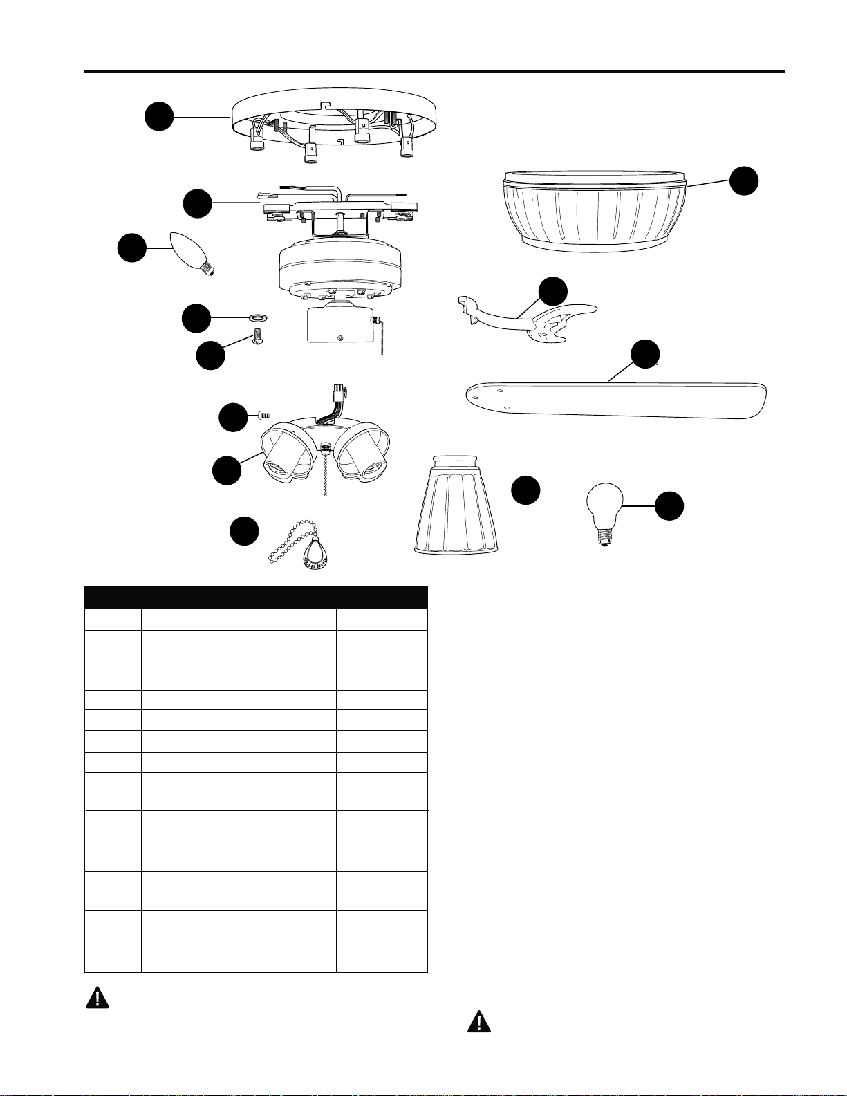
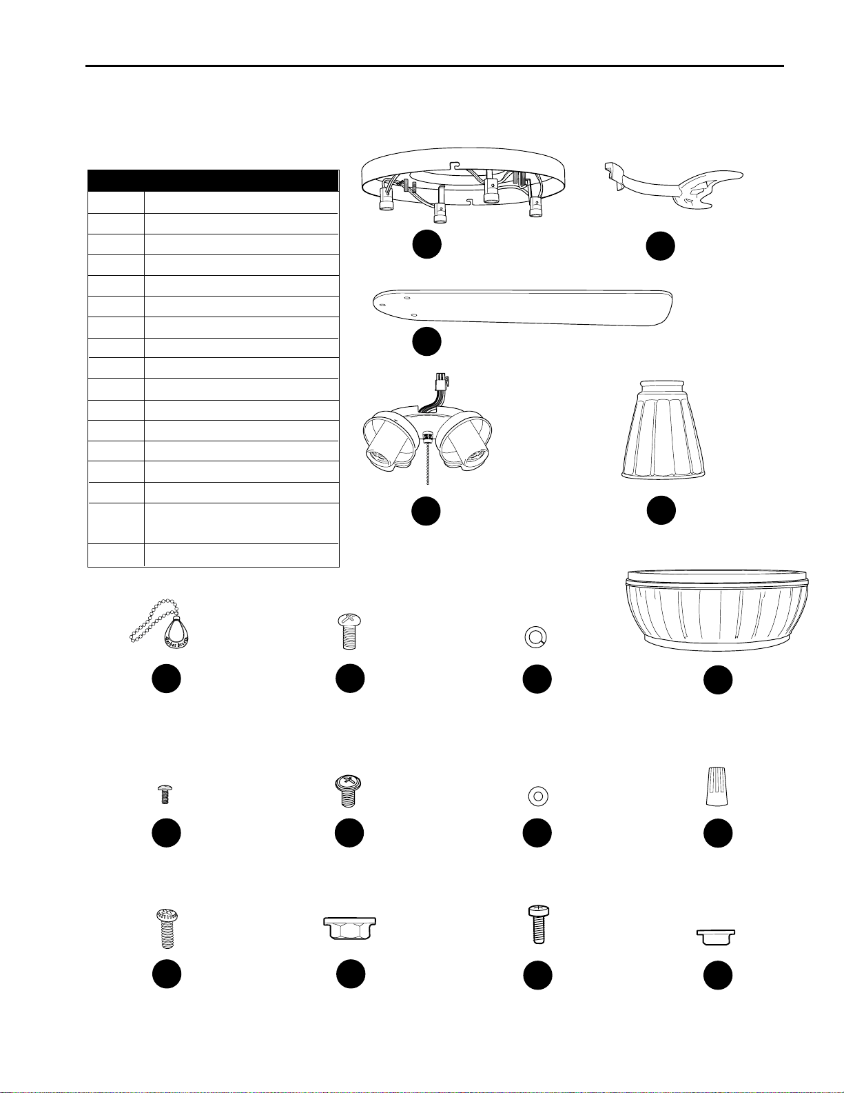
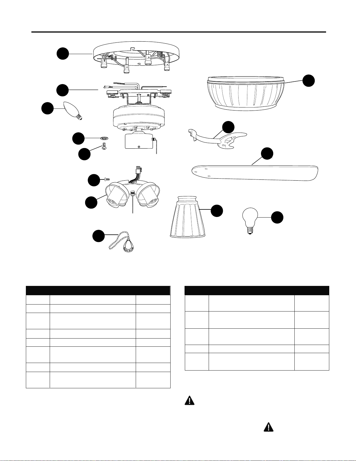
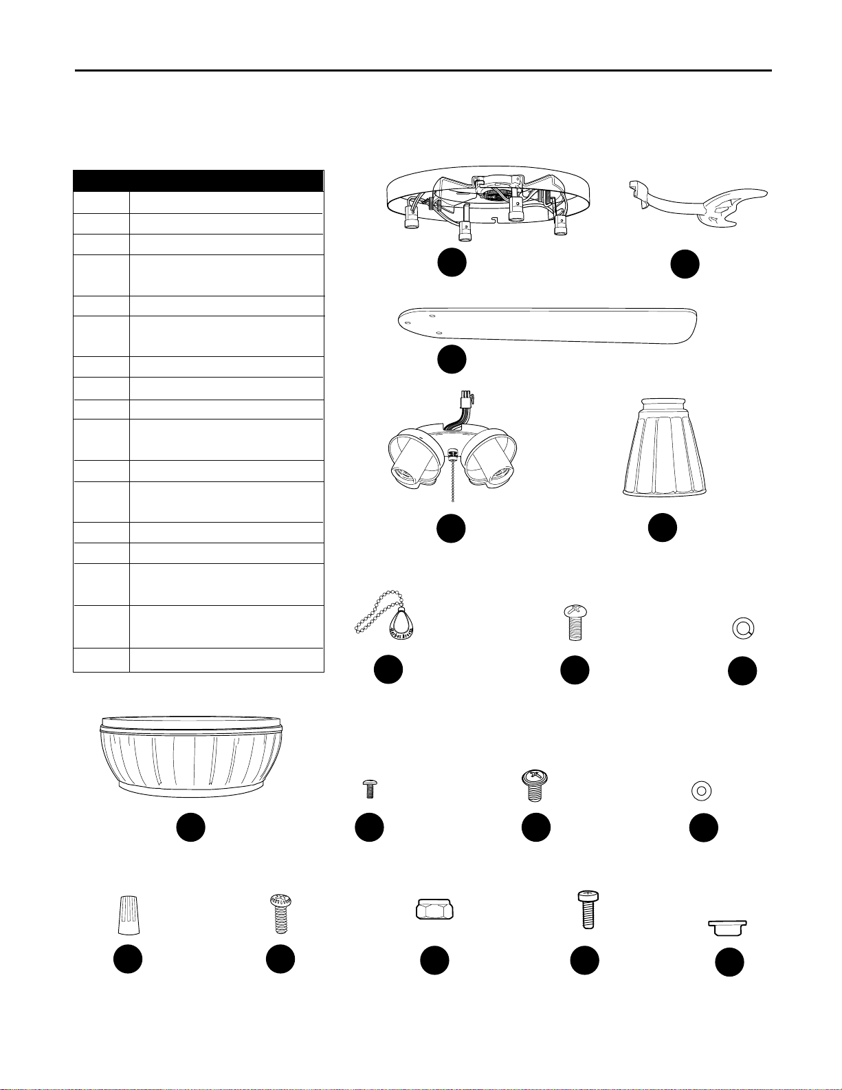
PACKAGE CONTENTS
IMPORTANT REMINDER: You must use the parts
provided with this fan for proper installation and safety.
PART DESCRIPTION QUANTITY
A Mounting Plate
1
B
Motor Assembly 1
C
Candelabra-base 7-watt
4
Bulb
D
Blade Arm 5
E
Blade 5
F Light Kit Fitter 1
G
Glass Shade 4
H
Candelabra-base 60-watt
4
Bulb
I
Pull Chain Extension 2
J Motor Screw 10
(preassembled) + 1 extra
K
Lock Washer 10
(preassembled) + 1 extra
L Motor Housing
1
M Switch Housing Screw
3
(preassembled)
4
A
E
F
C
H
I
G
J
K
B
L
D
M
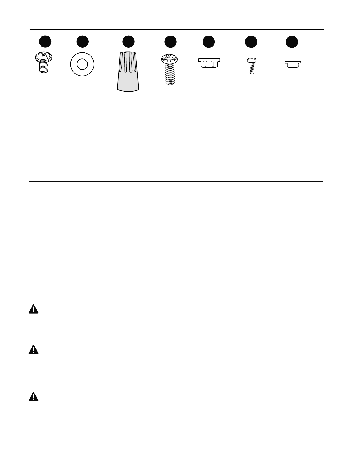
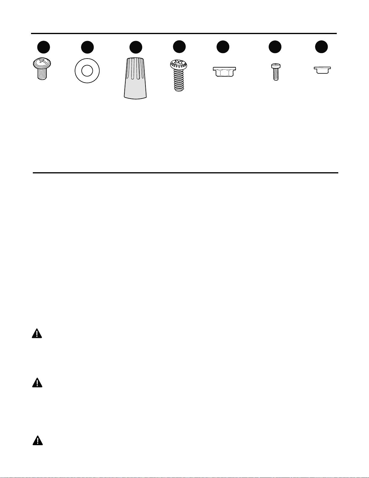
HARDWARE CONTENTS
(shown actual size)
Fiber
Blade
Washer
Qty. 15
+ 1 extra
BB CC
AA
Blade
Screw
Qty. 15
+ 1 extra
E3 Wire
Connector
Qty. 4
Before beginning assembly and installation of product, make sure all parts are present. Compare
parts with package contents list and hardware contents above. If any part is missing or
damaged, do not attempt to assemble, the product. Contact customer service for replacement parts.
Estimated Assembly Time: 120 minutes
Tools Required for Assembly (not included): Electrical Tape, Phillips Screwdriver, Pliers, Safety
Glasses, Stepladder and Wire Strippers
Helpful Tools (not included): AC Tester Light, Tape Measure, Do-It-Yourself Wiring Handbook
(available at Lowe’s) and Wire Cutters
Bulbs Required (included): 4 candelabra-base 7-watt max. bulbs--for lighted housing
4 candelabra-base 60-watt max. bulbs--for light kit
DANGER: When using an existing outlet box, make sure the outlet box is securely attached to
the building structure and can support the full weight of the fan. Failure to do this can result in serious
injury or death. The stability of the outlet box is essential in minimizing wobble and noise in the fan
after installation is complete.
CAUTION: Be sure outlet box is properly grounded and that a ground wire (green or bare) is
present.
After opening top of carton, remove mounting hardware package from foam inserts. Remove motor
from packing and place on carpet or on foam to avoid damage to finish.
CAUTION: Carefully check all screws, bolts and nuts on fan motor assembly to ensure that they
are secured.
PREPARATION
5
DD
Thumb
Screw
Qty. 12
+ 1 extra
EE
Mounting
Plate
Nut
Qty. 4
FF
Motor
Housing
Mounting
Screw
Qty. 4
GG
Bushing
Qty. 4
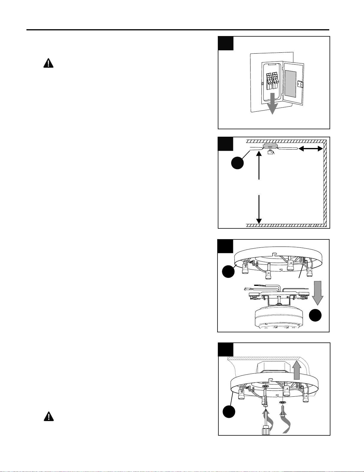
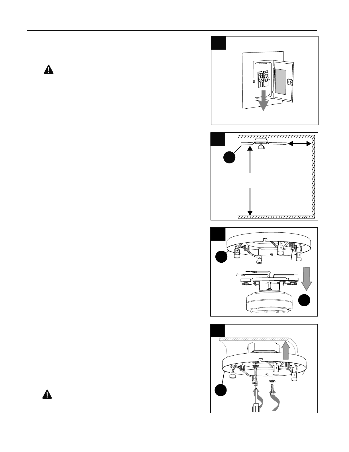
INITIAL INSTALLATION
Check to make sure blades (E) are at least 30 in.
from any obstruction and at least 7 ft. above the
floor. (Fig. 2)
1
ON
OFF
ON
OFF
Turn off circuit breakers and wall switch to the fan
supply line leads. (Fig. 1)
DANGER: Failure to disconnect power
supply prior to installation may result in serious
injury or death.
1.
2.
6
7 ft.
min.
30 in.
min.
2
E
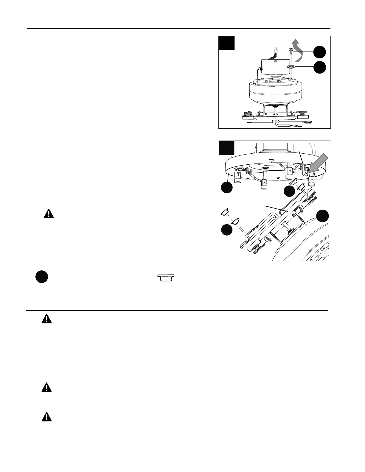
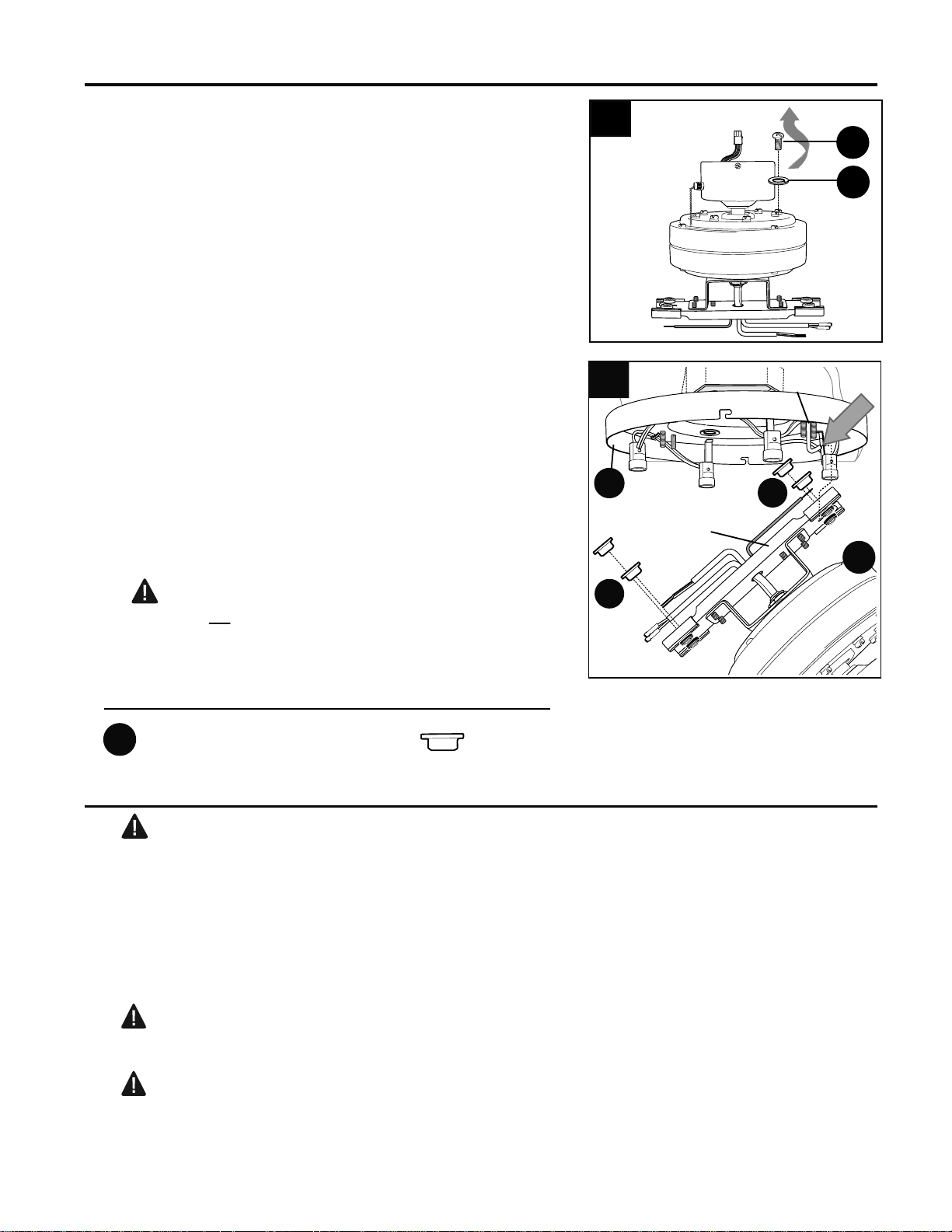
3.
Before proceeding, make sure that motor
assembly (B) and mounting plate (A) do not
remain connected to one another after they have
been removed from the box. If necessary,
disengage motor assembly (B) from “J” hook on
mounting plate (A) so that motor assembly (B) can
be separated from mounting plate (A). (Fig. 3)
3
4.
Secure mounting plate (A) to outlet box using
screws, spring washers, and flat washers
provided with the outlet box. (Fig. 4) Pull wires
from outlet box through center hole in mounting
plate (A).
*Note: It is very important that you use the proper
hardware when installing the mounting plate (A)
as this will support the fan.
CAUTION: Be sure outlet box is properly
grounded or that a ground (green or bare) wire is
present.
A
4
A
B
"J" Hook
7
A
"J" Hook
Bar
B
INITIAL INSTALLATION
6
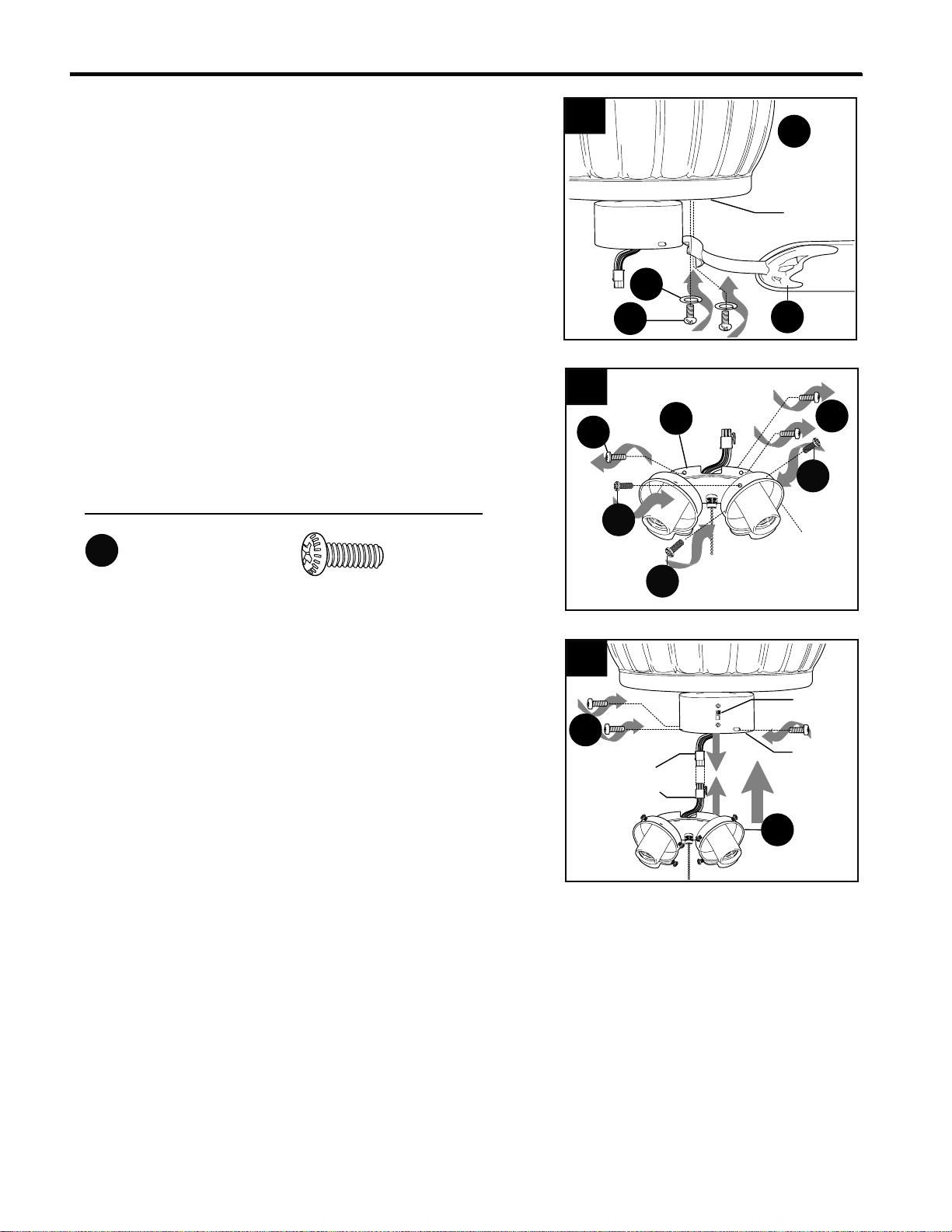
Locate holes that are reinforced with black rubber
in bar at top of motor assembly (B). Insert one
bushing (GG) into each of these holes. (Fig. 6)
Now, using the SLOTTED hole in the bar at the top
of the motor assembly (B), slide the bar over the "J"
hook on the mounting plate (A)--this will support the
fan during wiring. (Fig. 6)
WARNING: To reduce the risk of personal
injury, do not use any of the other holes in the bar
at the top of the motor assembly (B) to hang the
motor assembly (B) on the mounting plate (A).
6.
Caution: Be sure wiring box is properly
grounded and that a ground (green or bare) wire is
present.
WIRING
Warning: If house wires are different colors than
referred to in the following steps, stop immediately. A
professional electrician is recommended to determine
wiring.
WARNING: To reduce the risk of fire, electrical
shock, or personal injury, wire connectors provided
with this fan are designed to accept only one 12
gauge house wire and two lead wires from the fan. If
your house wire is larger than 12 gauge or there is
more than one house wire to connect to the two fan
lead wires, consult an electrician for the proper size
wire connectors to use.
5.
Remove motor screws (J) and lock washers (K)
from underside of motor and save for blade arm
(D) attachment later on. (Fig. 5)
5
K
J
Bushing x4
Hardware Used
GG
GG
GG
8
WIRING
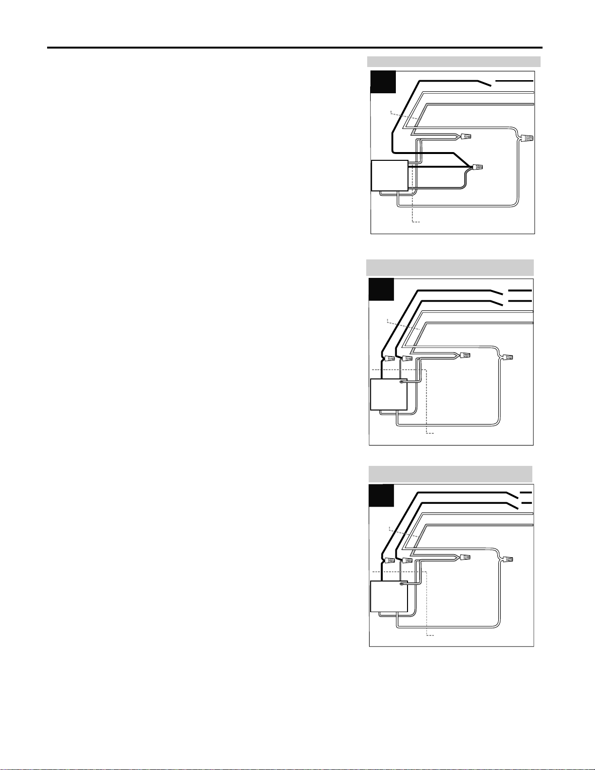
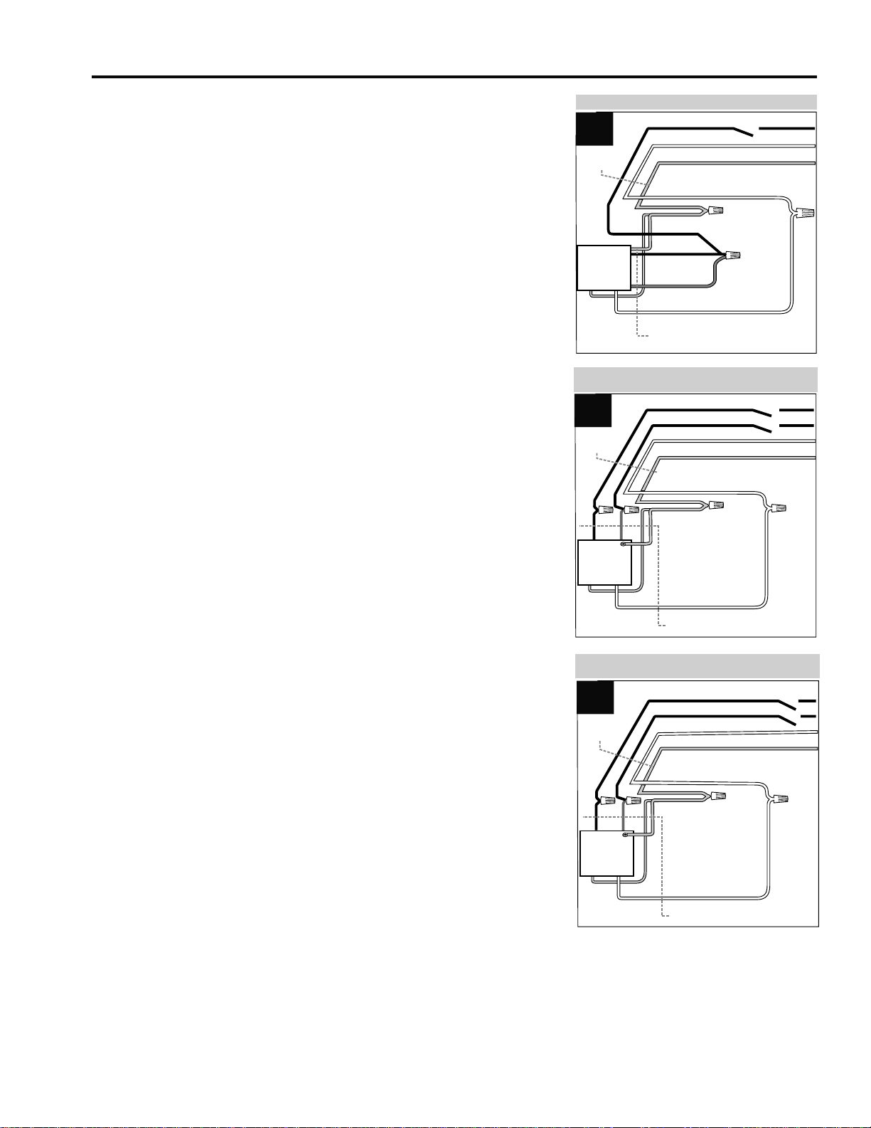
Choose wiring diagram (Fig. 1A, Fig. 1B or Fig. 1C)
that fits your situation and make appropriate wiring
connections as follows: [NOTE: For each wire
connection below, use one of the wire connectors
(CC) provided, making sure to screw wire connector
(CC) on in a clockwise direction.]
1A. FAN AND LIGHT CONTROLLED BY PULL
CHAINS: Connect BLACK and BLUE wire from fan
to BLACK wire from ceiling. Connect WHITE wire
from fan to WHITE wire from ceiling. Connect all
GROUND (GREEN) wires together from fan (on
motor assembly (B) and mounting plate (A)) to
BARE/GREEN wire from ceiling. (Fig. 1A)
1B. FAN CONTROLLED BY PULL CHAIN, LIGHT
BY WALL SWITCH: If you intend to control the fan
light with a separate wall switch, connect BLACK
wire from fan to BLACK wire from ceiling. Connect
BLUE wire from fan to the BLACK wire from the
independent wall switch for the light. Connect
WHITE wire from fan to WHITE wire from ceiling.
Connect all GROUND (GREEN) wires together from
fan (on motor assembly (B) and mounting plate (A))
to BARE/GREEN wire from ceiling. (Fig. 1B)
1C. FAN AND LIGHT CONTROLLED BY TWO
WALL SWITCHES: If you intend to control the fan
and light with separate wall switches, connect
BLACK wire from fan to BLACK wire from the
independent wall switch for the fan. Connect BLUE
wire from fan to the BLACK wire from the other
independent wall switch for the light. Connect
WHITE wire from fan to WHITE wire from ceiling.
Connect all GROUND (GREEN) wires together from
fan (on motor assembly (B) and mounting plate (A))
to BARE/GREEN wire from ceiling. (Fig. 1C)
Note: Black wire is hot power for fan. Blue wire is
hot power for light kit. White wire is common for fan
and light kit. Green or bare wire is ground.
1.
FAN AND LIGHT CONTROLLED BY PULL CHAINS
BLACK
WHITE
GROUND/GREEN (BARE)
WHITE
BLUE
WHITE
FROM FAN
120 V Power
FROM
CEILING
FAN CONTROLLED BY PULL CHAIN, LIGHT BY
WALL SWITCH
WHITE
BLACK
BLACK (WALL SWITCH)
GROUND/GREEN (BARE)
BLACK
BLUE
WHITE
FROM FAN
FAN
120 V Power
FROM
CEILING
WHITE
BLACK (WALL SWITCH)
BLACK (WALL SWITCH FOR LIGHT)
GROUND/GREEN (BARE)
BLACK
BLUE
WHITE
FROM FAN
FAN
120 V Power
FROM
CEILING
FAN AND LIGHT CONTROLLED BY TWO WALL
SWITCHES
FAN
GREEN
GREEN
BLACK
GREEN
WHITE
WHITE
1A
1B
1C
GREEN
GREEN
GREEN
9
WIRING
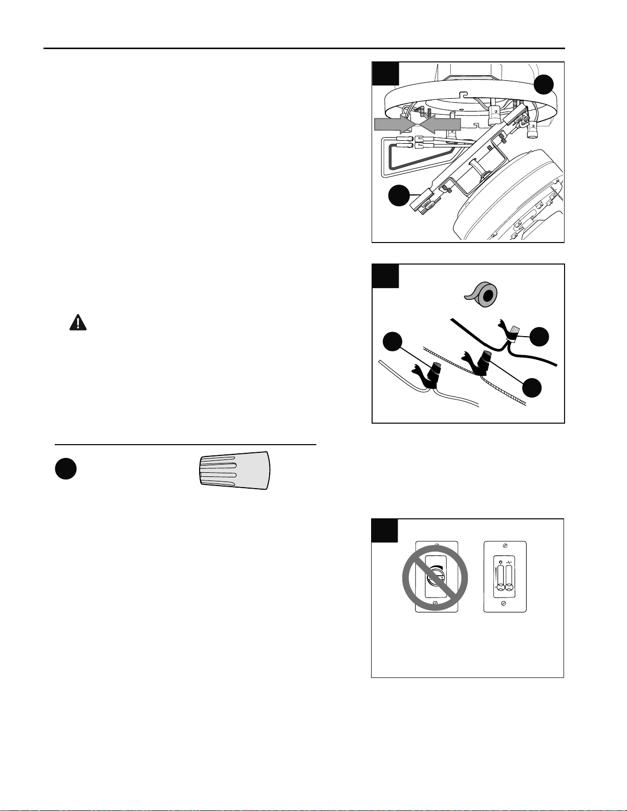
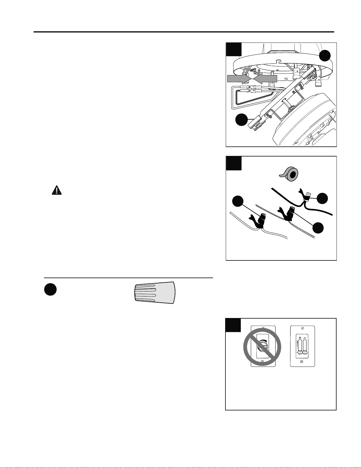
Wrap electrical tape (not included) around each
individual wire connector (CC) down to the wire as
shown in Fig. 3.
WARNING: Make sure no bare wire or wire
strands are visible after making connections. Place
green and white connections on opposite side of box
from the black and blue (if applicable) connections.
Turn spliced/taped wires upward and gently push
wires and wire connectors (CC) into outlet box.
E3 Wire Connector x4
3.
Hardware Used
3
CC
CC
CC
CC
CC
Locate the two WHITE wires labeled "INTERIOR
LIGHT" in the mounting plate (A) and the two molex
connections (one RED wire, one WHITE wire) at the
top of the motor assembly (B) and connect these
wires. (Fig. 2) Make sure that molex connections are
secure.
2.
2
B
A
IMPORTANT: Using a full range dimmer switch to
control fan speed will cause a loud humming noise
from fan. To reduce the risk of fire or electrical shock,
do NOT use a full range dimmer switch to control fan
speed. (Fig. 4)
*PLEASE NOTE: Must have third wire in wall to use
wall control (speed switch) such as the one shown at
right.
4
1
2
3
Dimmer
Switch
Speed
Switch
For illustrative purposes only--not
intended to cover all types of controls
4.

10
FINAL INSTALLATION
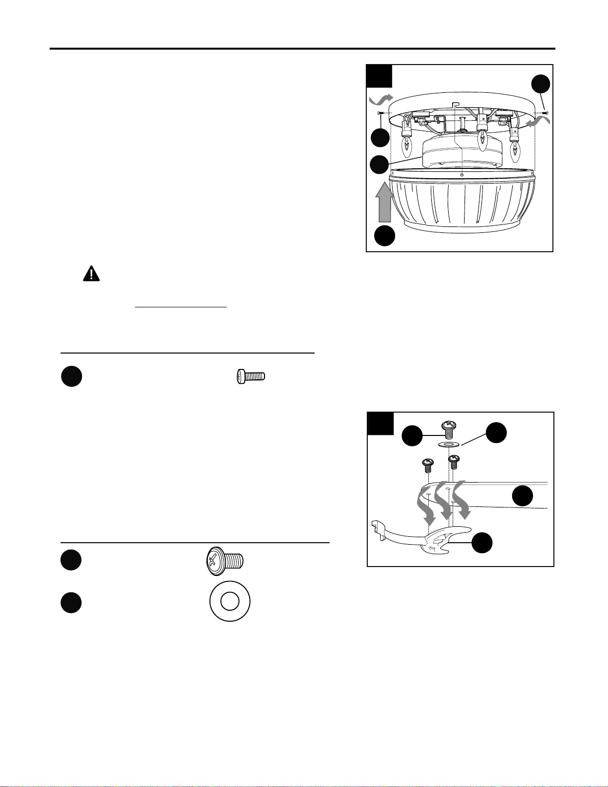
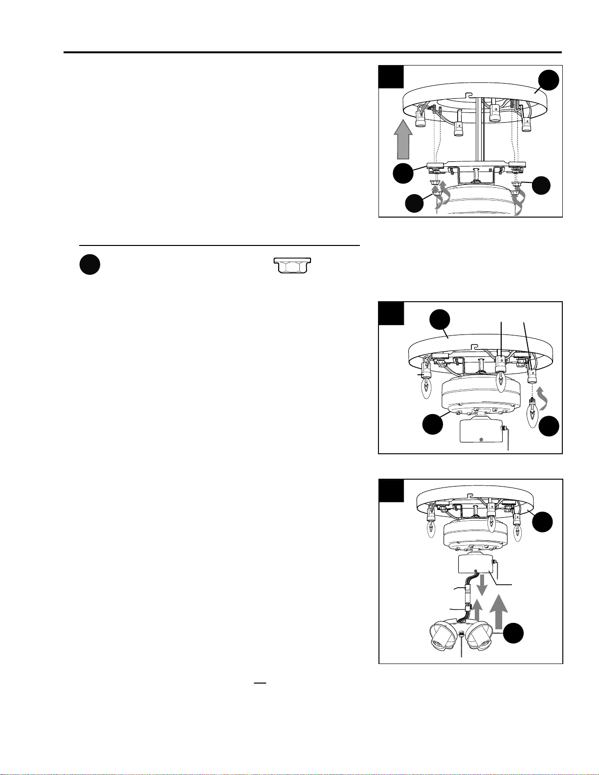
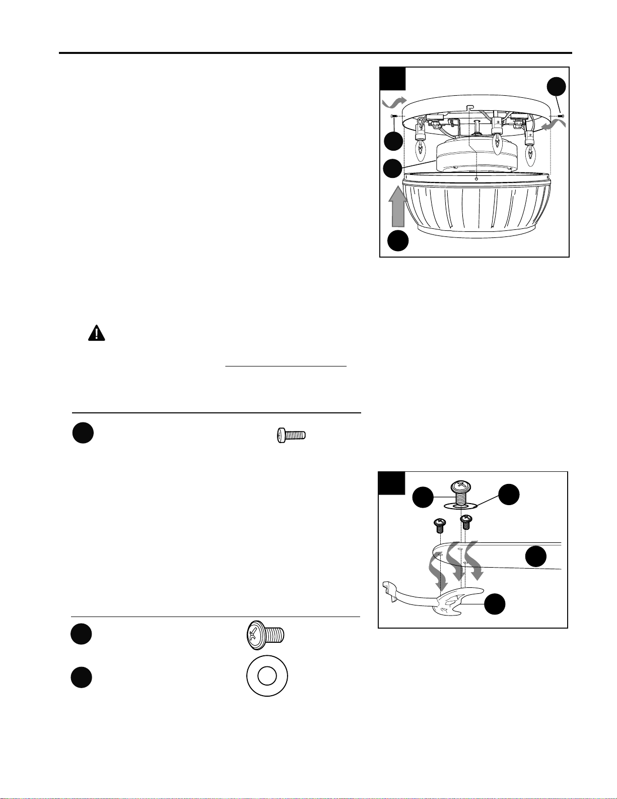
Install the four 7-watt candelabra base bulbs (C)
provided into the sockets on the mounting plate (A).
(Fig. 2)
2.
1.
A
B
1
Locate mounting plate nuts (EE) in one of the
hardware packs.
Remove motor assembly (B) from "J" hook. Align
holes in the bar at the top of the motor assembly (B)
with bolts on underside of mounting plate (A) and
push up until bolts come all the way through the
holes. Secure motor assembly (B) with mounting
plate nuts (EE). (Fig. 1) Make sure to tighten all
mounting plate nuts (EE) completely.
Socket
CC
EE
EE
2
B
C
A
Socket
Mounting Plate Nut x4
Hardware Used
EE
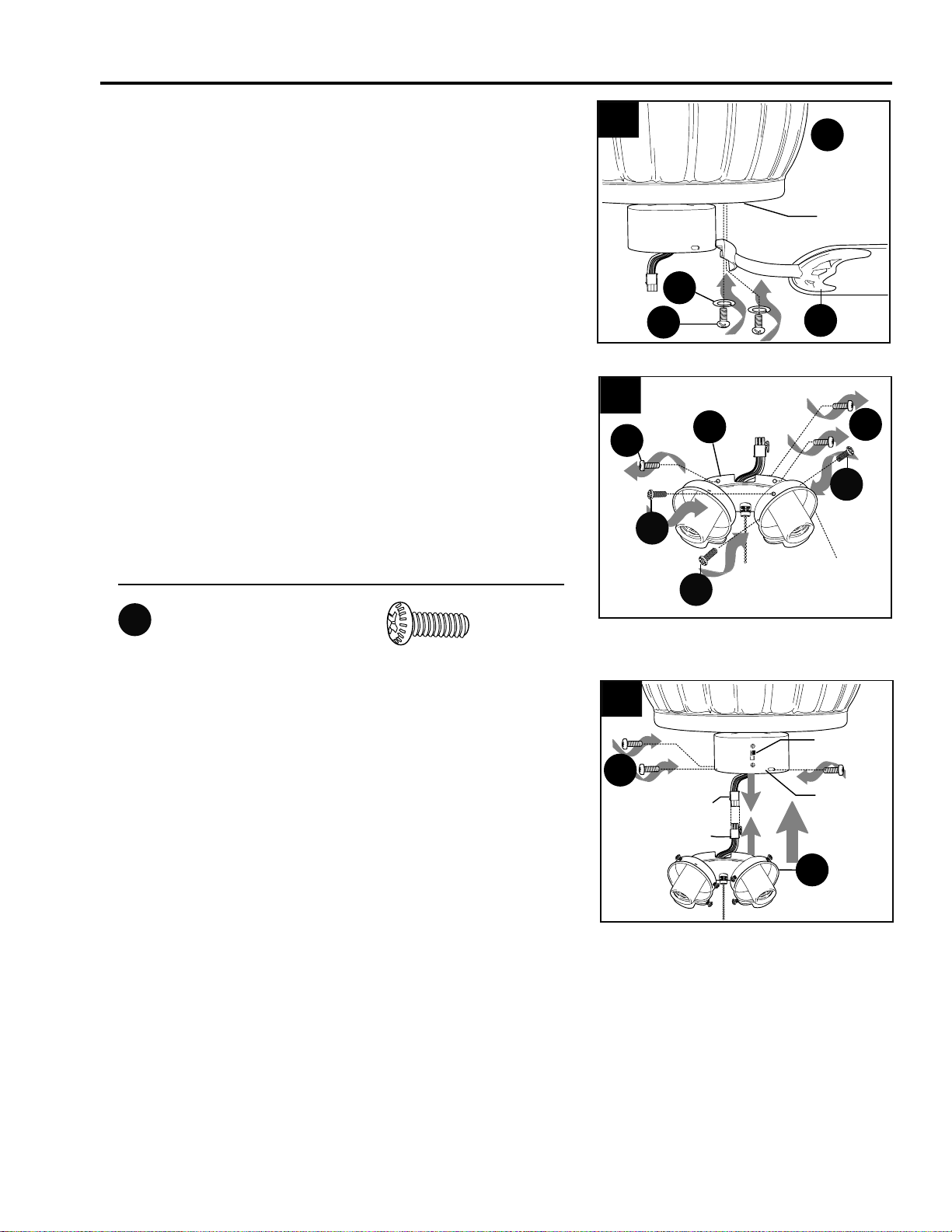
It is advisable to check that the wiring has been
done correctly before proceeding. Connect the
male plug from the switch housing to the female
plug from the light kit fitter (F). Make sure that the
plugs connect tightly. (Fig. 3)
Turn power on and then pull the chain on the light
kit fitter (F). The lights on the mounting plate (A)
should light up. Turn power back off and
disconnect male and female plugs. If mounting
plate (A) lights came on, please continue with
Step 4 on the following page; if mounting plate (A)
lights did not come on, repeat instructions in
“WIRING” section.
3.
3
Switch
Housing
Male Plug
Female Plug
F
A
Locate four motor housing mounting screws (FF) in
hardware pack. Temporarily lift motor housing (L)
to mounting plate (A) to determine which of the
four holes in motor housing (L) align with the two
slotted holes in mounting plate (A). Lower motor
housing (L) and partially insert one motor housing
mounting screw (FF) in each hole in motor housing
(L) that aligned with one of the slotted holes. Slide
motor housing (L) over mounting plate (A), aligning
loosened motor housing mounting screws (FF) in
motor housing (L) with slotted holes in mounting
plate (A). Twist motor housing (L) to lock. Insert the
other two motor housing mounting screws (FF) and
tighten all four motor housing mounting screws
(FF) securely. (Fig. 4)
CAUTION: Do NOT use power tools to
avoid breakage or cracking of the motor housing
(L). Use a HAND screwdriver to tighten screws
instead.
FINAL INSTALLATION
11
4.
4
L
B
FF
FF
B
AA
Blade Screw x15
Fiber Blade Washer x15
BB
Hardware Used
5.
Before proceeding, make sure electricity has
been SHUT OFF.
Partially insert three blade screws (AA), along with
three fiber blade washers (BB), to attach one blade
arm (D) to a blade (E). Then, tighten each blade
screw (AA), starting with the one in the middle.
(Fig. 5) Repeat with remaining blades (E).
E
5
D
AA
BB
Motor Housing Mounting x4
Screw
Hardware Used
FF
12
FINAL INSTALLATION
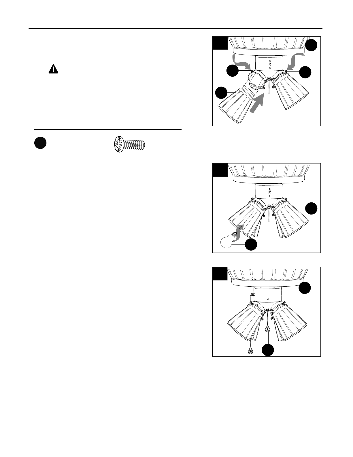
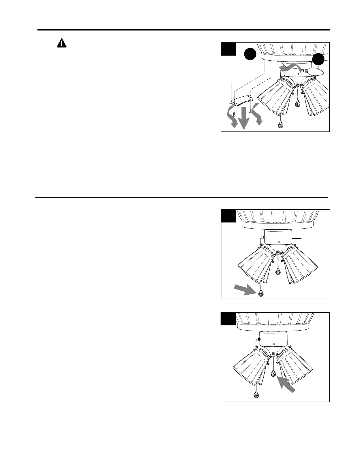
Re-connect male plug from switch housing to
female plug from light kit fitter (F). Make sure that
the plugs connect tightly. (Fig. 8)
Align holes in switch housing with holes in light kit
fitter (F)--the opening in the top edge of the light kit
fitter (F) should align with the reverse switch for a
secure fit. Attach light kit fitter (F) with the three
switch housing screws (M) that were removed in
the previous step. (Fig. 8)
8.
Switch
Housing
Reverse
Switch
Male Plug
Female Plug
8
F
M
Remove three switch housing screws (M) from light
kit fitter (F) and set aside. Then, locate thumb
screws (DD) provided in one of the hardware
packs. Partially insert thumb screws (DD) into
holes in socket covers on light kit fitter (F). (Fig. 7)
7.
Socket
Cover
F
7
DD
DD
DD
M
M
Thumb Screw x12
Hardware Used
DD
Locate motor screws (J) and lock washers (K) that
were removed in Step 5 on page 7.
Insert two motor screws (J), along with lock
washers (K), through one blade arm (D) to attach
blade arm (D) to motor. Tighten motor screws (J)
securely. (Fig. 6) Repeat with remaining blade
arms (D), making sure to completely secure each
blade arm (D) before proceeding with the next.
6.
K
J
D
6
L
Motor
FINAL INSTALLATION
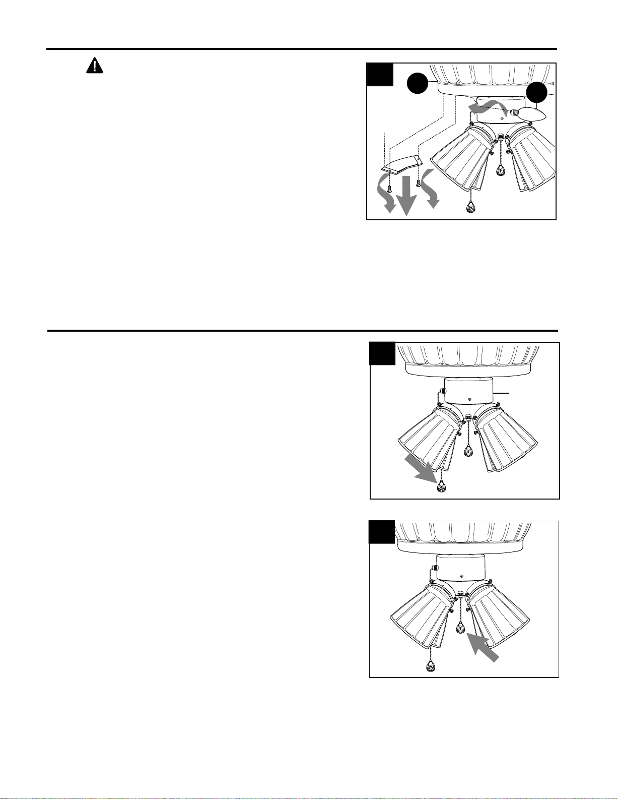
Install glass shades (G) by tightening thumb
screws (DD) that were installed in Step 7 on the
previous page. (Fig. 9)
CAUTION: Do NOT use power tools to tighten
thumb screws in order to avoid breakage of glass.
Tighten thumb screws (DD) HAND-tight ONLY.
Note: Do not overtighten thumb screws (DD) as
glass may crack or break.
9.
13
9
G
DD
DD
L
Hardware Used
The pull chain extensions (I) supplied in one of the
hardware packs or custom pull chains extensions
(sold separately) may be attached to fan and light
pull chains. (Fig. 11)
11.
I
11
Install four candelabra-base 60-watt max. bulbs (H)
included. (Fig. 10)
IMPORTANT: When you need to replace bulbs,
please allow the bulbs and glass shades to cool
down before touching them.
10.
10
G
H
L
Thumb Screw x12
DD
14
Locate four access covers in the bottom of the
motor housing (L). Determine which access cover(s)
will need to be removed to access burned out
bulb(s) (C). Remove two screws from each access
cover that will need to be removed. Remove each
burned out bulb (C) and replace with a
candelabra-base 7-watt max. bulb. (Fig. 1)
LIGHTED HOUSING BULB REPLACEMENT
CAUTION: Allow motor housing (L) and bulbs
(C) to cool before trying to access bulbs (C) in
lighted housing.
Replace access cover(s) with screws that were
removed.
1
Access
Cover
C
1.
L
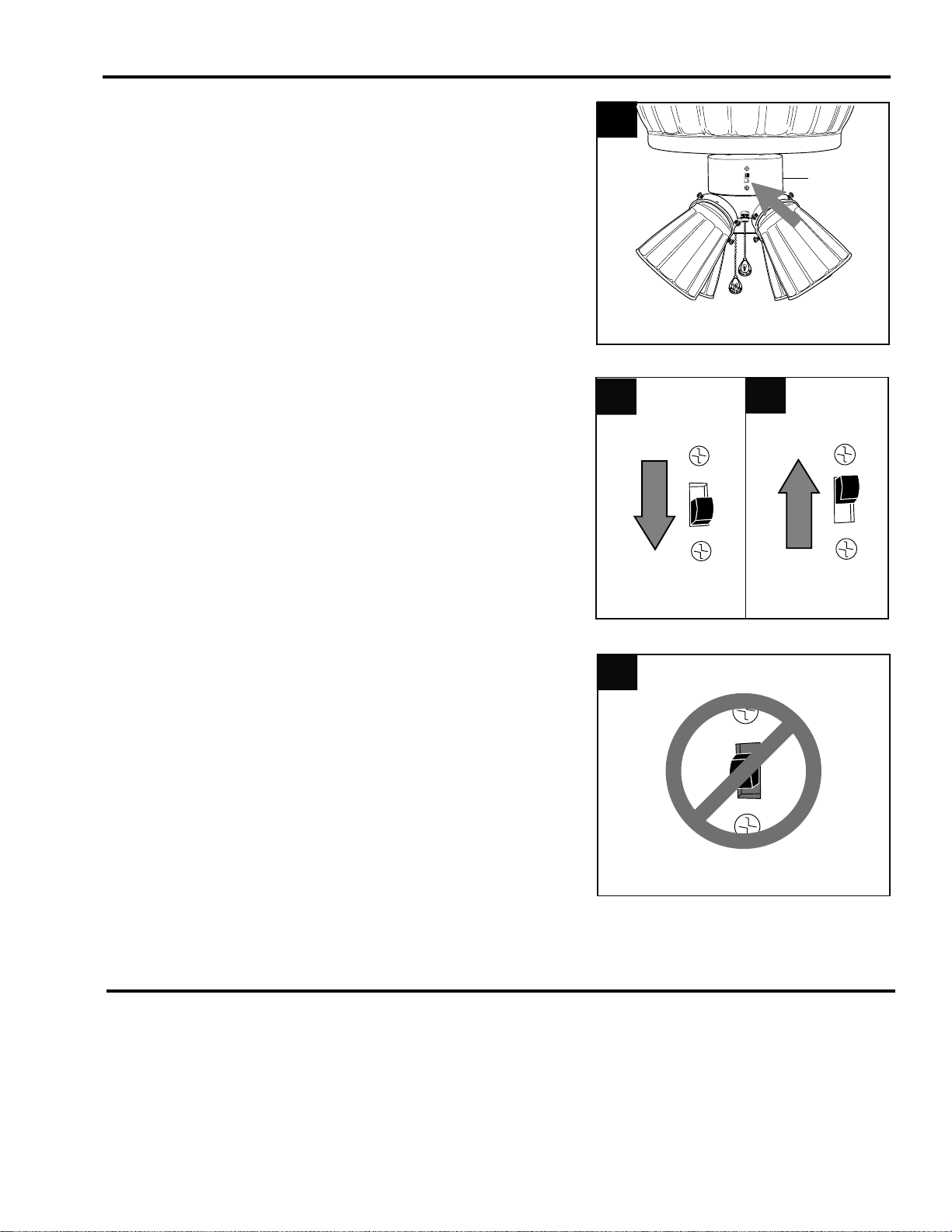
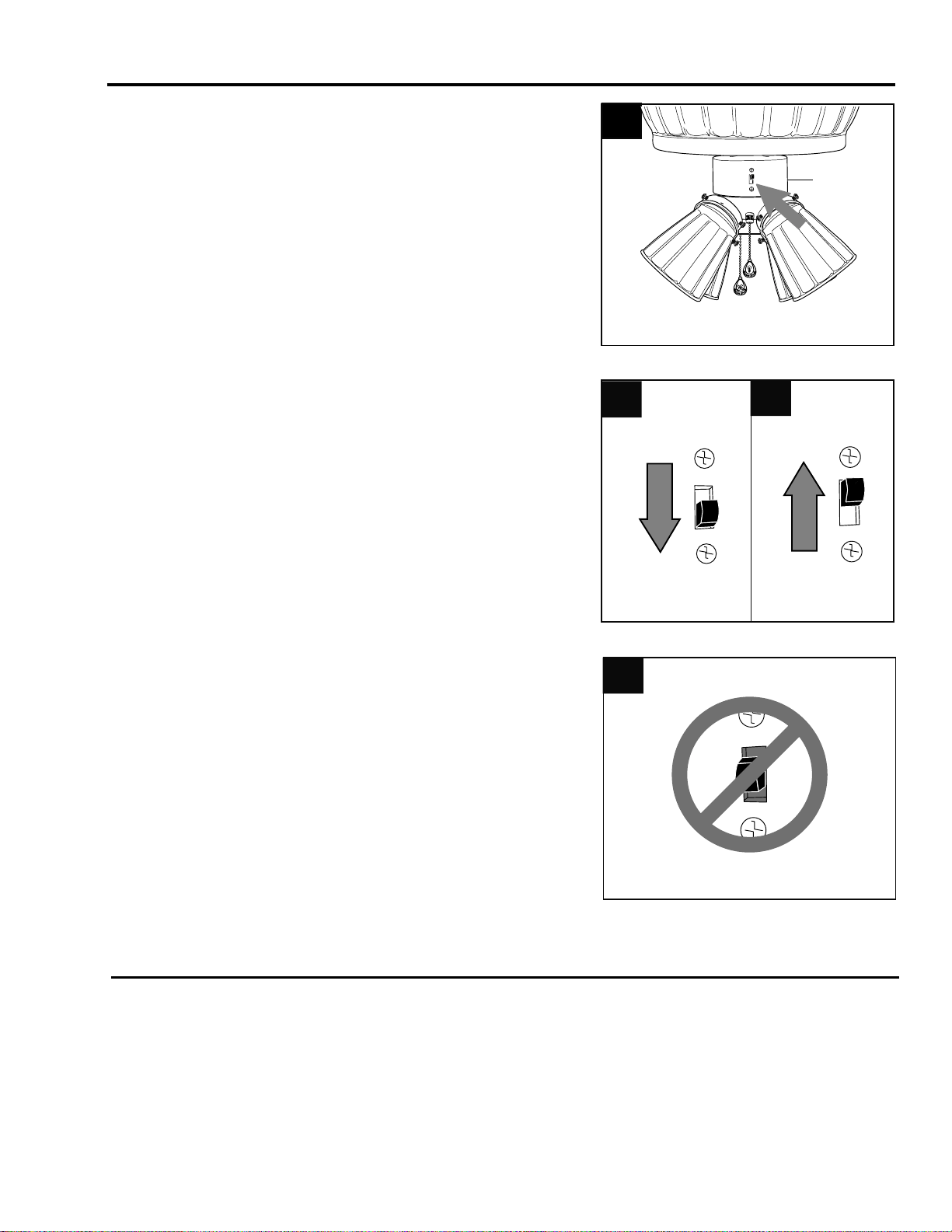
The pull chain located on the switch housing has
four positions to control fan speed. One pull is
HIGH, two is MEDIUM, three is LOW and four
turns the fan OFF. (Fig. 1)
1.
OPERATION INSTRUCTIONS
The pull chain located in the center has four
positions to control the lights. One pull turns the
LOWER lights (light kit) on, two pulls turns the
UPPER lights (lighted housing) on, three pulls turns
ALL of the lights on, and four pulls turns ALL of the
lights OFF. (Fig. 2)
2.
Switch
Housing
1
2
15
OPERATION INSTRUCTIONS
3.
Use the fan reverse switch, located on the switch
housing, to optimize your fan for seasonal
performance. (Fig. 3) A ceiling fan will allow you to
raise your thermostat setting in summer and lower
your thermostat setting in winter without feeling a
difference in your comfort.
Note: Wait for fan to stop before moving the
reverse switch.
3A
3B
3
Switch
Housing
3A. In warmer weather, setting the reverse
switch in the DOWN position will result in
downward airflow creating a wind chill effect.
(Fig. 3A)
3B. In cooler weather, setting the reverse switch
in the UP position will result in upward airflow
that can help move stagnant, hot air off the
ceiling area. (Fig. 3B)
At least twice each year, tighten all screws on fan. Clean motor housing unit (B) with only a soft brush
or lint-free cloth to avoid scratching the finish. Clean blades (E) with a lint-free cloth. You may
occasionally apply a light coat of furniture polish to wood blades for added protection.
IMPORTANT: Shut off main power supply before beginning any maintenance. Do not use water or a
damp cloth to clean the ceiling fan.
CARE AND MAINTENANCE
3C
3C. IMPORTANT: Reverse switch must be set
either completely UP or completely DOWN
for fan to function. If the reverse switch is set
in the middle position (Fig. 3C), fan will not
operate.
If you have any questions regarding the product please call customer service at 1-800-527-1292, 8:30
a.m. - 5 p.m., CST, Monday - Friday.
WARNING: Before beginning work, shut off the power supply to avoid electrical shock.
Fan does not operate. 1. Reverse switch not engaged. 1. Push switch firmly either up or
down.
2. Power is off or fuse is blown. 2. Turn power on or check fuse.
3. Male and female plugs not 3. Check that male and female
connected properly. plugs are connected properly
according to instructions on page
12.
Noisy operation. 1. Blades (E) are loose. 1. Tighten all blade screws (AA).
2. Cracked blade (E). 2. Replace blade (E).
3. Full range dimmer switch. 3. Replace with an approved speed
control device.
4. Fan is new. 4. Allow fan a "break in" period of a
few days, especially when running
the fan at Medium and High
speeds.
5. Motor housing (L) is loose. 5. Turn power off. Carefully loosen
motor housing (L) and verify that
mounting plate (A) is secure
according to instructions on
page 6.
Excessive wobbling. 1. Blades (E) are loose. 1. Tighten all blade screws (AA).
2. Blade arms (D) incorrectly 2. Re-install blade arms (D).
attached.
3. Unbalanced blades (E). 3. Switch one blade (E) with blade
(E) from opposite side.
4. Fan not securely mounted. 4. Turn off power. Carefully loosen
motor housing (L) and verify that
mounting plate nuts (EE) are
secure.
Fan operates but lights 1. Bulb(s) not installed correctly. 1. Re-install bulb(s).
fail. 2. Wires in outlet box not wired 2. Check wires in outlet box and, if
properly. necessary, re-wire according to
"Wiring" instructions on pages 8
and 9.
3. Wall switch to fan is off. 3. Make sure that wall switch to fan
is on.
4. Plugs not connected properly. 4. Check that plugs are connected
properly according to instructions
on page(s) 9 and/or 12.
TROUBLESHOOTING
PROBLEM POSSIBLE CAUSE CORRECTIVE ACTION
16
Note: A small amount of "wobble" is normal and should not be considered a defect.

17
WARRANTY
LIMITED LIFETIME WARRANTY: Litex Industries warrants this fan to be free from defects in
workmanship and materials present at time of shipment from the factory for Lifetime limited from the
date of purchase. This warranty applies only to the original purchaser. Litex Industries agrees to
correct any defect at no charge or, at our option, replace the ceiling fan with a comparable or superior
model.
To obtain warranty service, present a copy of your sales receipt as proof of purchase. All cost of
removal and reinstallation are the express responsibility of the purchaser. Any damage to the ceiling
fan by accident, misuse or improper installation, or by using parts not produced by the manufacturer
of this fan or affixing accessories not produced by the manufacturer of this fan, are the purchaser's
own responsibility. Litex Industries assumes no responsibility whatsoever for fan installation during
the limited lifetime warranty. Any service performed by an unauthorized person will render the
warranty invalid.
Due to varying climatic conditions, this warranty does not cover changes in brass finish, rusting,
pitting, tarnishing, corroding or peeling. Brass finish fans maintain their beauty when protected from
varying weather conditions. Any glass provided with this fan is not covered by the warranty.
Any replacement of defective parts for the ceiling fan must be reported within the first year from the
date of purchase. For the balance of the warranty, call our customer service department (at
1-800-527-1292) for return authorization and shipping instructions so that we may repair or replace
the ceiling fan. Any fan or parts returned improperly packaged is/are the sole responsibility of the
purchaser. There is no further express warranty. Litex Industries disclaims any and all implied
warranties. The duration of any implied warranty which cannot be disclaimed is limited to the limited
lifetime period as specified in our warranty. Litex Industries shall not be liable for incidental,
consequential or special damages arising at or in connection with product use or performance except
as may otherwise be accorded by law. This warranty gives you specific legal rights and you may also
have other rights which vary from state to state. This warranty supersedes all prior warranties.
Printed in China
PART DESCRIPTION
A
Mounting Plate
D
Blade Arm
E
Blade
F Light Kit Fitter
G
Glass Shade
I
Pull Chain Extension
J
Motor Screw
K
Lock Washer
L
Motor Housing
M Switch Housing Screw
AA
Blade Screw
BB
Fiber Blade Washer
CC E3 Wire Connector
DD
Thumb Screw
EE
Mounting Plate Nut
FF
Motor Housing Mounting
Screw
GG
Bushing
REPLACEMENT PARTS LIST
For replacement parts, call our customer service department at 1-800-527-1292, 8:30 a.m. - 5:00
p.m., CST, Monday - Friday. When ordering parts, please have the Model # or Item # of the fan
available, which can be found on page 1.
A
E
G
K
J
L
M
D
BB
FF
18
F
AA
GG
CC
DD EE
I
ARTICULO#0373645
E124404
VENTILADOR DE TECHO WOLCOTT
MODELO #WO52BB5C
19
Harbor Breeze® es marca registrada de
LF, LLC. Reservados todos los derechos.
¿Preguntas, problemas, faltan piezas? Antes de regresar a la tienda, llame o póngase en
contacto con nuestro departamento de servicio al cliente al 1-800-527-1292, de 8:30 a.m. a
5:00 p.m., hora central, de lunes a viernes.
ADJUNTE SU RECIBO AQUI
Número de serie
Fecha de compra
20
POR FAVOR LEA Y GUARDE ESTAS INSTRUCCIONES
Por favor lea el instructivo entero antes de tratar de ensamblar, instalar o hacer funcionar el producto.
Si tiene alguna pregunta acerca del producto, por favor llame al servicio al cliente al 1-800-527-1292,
de 8:30 a.m. a 5:00 p.m., hora central, de lunes a viernes.
• No deseche la caja del ventilador ni la goma espuma incluida. Si hay que mandar el ventilador a la
fábrica por alguna reparación, se debe enviar en su paquete original para asegurar la protección
apropiada contra daños que podrían exceder la causa inicial por la cual se devolvió.
• Asegúrese de que todas las conexiones eléctricas cumplen con los códigos y las ordenanzas
locales, con el Código Nacional Eléctrico (NEC, por sus siglas en inglés), y ANSI/NFPA 70-1999.
Contrate un electricista calificado o consulte una guía de instalación eléctrica de hágalo usted mismo,
disponible en Lowe's, si no está familiarizado con la instalación eléctrica.
• Asegúrese de que el lugar de instalación que usted escogió tiene un mínimo de 2,13 m de desde las
paletas hasta el piso y que la punta de las paletas quede a por lo menos 76,2 cm de cualquier
obstrucción.
• Después de instalar el ventilador, verifique que todas las conexiones estén seguras para que no se
caiga el ventilador.
• El peso neto del ventilador con el juego de luz es de: 9,3 kg.
INDICE DE MATERIAS
Información de seguridad ......…………………………………………
…..
..................20 - 21
Contenido del paquete ...................………………………………………………………..... 22
Contenido de artículos de ferretería ...................……………………………….................... 23
Preparación .............................................….…………………..………………................. 23
Instalación inicial ............................................…………………………………….........24 - 25
Conexión de los cables .........................................…………………………………….25 - 27
Instalación final ............……………….…………….…….………………….…...............28 - 31
El reponer las bombillas del bastidor iluminado ..........................................................................32
Instrucciones de funcionamiento ..............................................................................32 - 33
Cuidado y mantenimiento ........................…....……………………………………………....33
Localización de fallas .........................................…….......…………
………
.
.................
..
34 - 35
Garantía ........................……………………………
……….……………
....
…
…
…...
......
.…
..
......
35
Lista de piezas de repuestos ....................................................................................................36
INFORMACION DE SEGURIDAD
21
Para reducir el riesgo de incendios, choque eléctrico o daño corporal, sujete el ventilador
a una caja de salida marcada como "ACCEPTABLE FOR FAN SUPPORT OF 35 LBS
(15,9 KG) OR LESS" (acepatable para sostener un ventilador de 15,88 kg (35 lb) o
menos) y utilice los tornillos de montaje proporcionados con la caja de salida. La mayoría de las
cajas de salida que se usan comúnmente para sostener aparatos de alumbrado no son
aceptables para sostener ventiladores y es posible que sea necesario reemplazarla. Consulte
con un electricista calificado si tiene alguna duda.
Al instalar el ventilador en una caja de salida del techo, use una caja de salida octogonal de
METAL. Asegure la caja de salida directamente a la estructura del edificio. La caja de salida
y su soporte deben poder sostener el peso móvil del ventilador (por lo menos 15,88 kg). NO use
una caja de salida plástica.
Para reducir el riesgo de daño corporal, es posible que sea necesario usar guantes al manejar
las piezas del ventilador que tengan bordes afilados.
Para reducir el riesgo de incendio, choque eléctrico o daño corporal, los conectores para cable
provistos con este ventilador son diseñados para aceptar sólo un cable de calibre 12 de la casa y
dos cables principales del ventilador. Si el calibre del cable de la casa es superior al 12 o hay
más de un cable de la casa para conectar a los cables principales del ventilador, consulte con un
electricista para informarse sobre el tamaño correcto de conectores para cable que se debe usar.
Para reducir el riesgo de incendio o un choque eléctrico, no use el ventilador con ningún
control de velocidad de estado sólido ni controle la velocidad del ventilador con un
interruptor con reductor de luz de gama completa.
Para reducir el riesgo de incendio, choque eléctrico o lesión personal, no doble brazos de las
paletas mientras las esté instalando, ni cuando esté balanceando las paletas ni cuando esté
limpiando el ventilador. No inserte objetos entre las paletas giratorias del ventilador.
Para reducir el riesgo de lesión personal, use sólo las piezas provistas con este ventilador. Al
usar piezas DISTINTAS a las provistas con este ventilador se invalidará la garantía.
ADVERTENCIAS
PRECAUCIONES
Antes de proseguir, desconecte la electricidad, quitando los fusibles o cortando el suministro de
energía de los circuitos para evitar un choque eléctrico
.
Lea todas las instrucciones y la información de seguridad antes de instalar su ventilador nuevo.
Revise los diagramas de ensamblaje acompañantes.
INFORMACION DE SEGURIDAD
RECORDATORIO IMPORTANTE: Se
tienen que utilizar las piezas provistas con
este ventilador para una instalación
adecuada y su seguridad.
A
Placa de montaje 1
B
Unidad del motor 1
C
Bombilla de base 4
candelabro de 7 vatios
D
Brazo para la paleta 5
E
Paleta 5
F Conectador para el juego 1
de luz
G
Pantalla de vidrio 4
H
Bombilla de base 4
candelabro de 60 vatios
22
CONTENIDO DEL PAQUETE
PIEZA DESCRIPCION CANTIDAD
I
Extensión para la cadena 2
de encendido
J
Tornillo del motor 10
(preensamblado) + 1 extra
K
Arandela de seguridad 10
(preensamblada) + 1 extra
L Bastidor del motor 1
M Tornillo de la caja del 3
interruptor (preensamblado)
PIEZA DESCRIPCION CANTIDAD
A
E
F
C
H
I
G
J
K
B
L
D
M
23
DD
Tornillo
de
mariposa
Ctd. 12
+ 1 extra
CONTENIDO DE ARTICULOS DE FERRETERIA (se muestra en tamaño natural)
Arandela
de fibra
para la
paleta
Ctd.15
+ 1 extra
BB CC
AA
Tornillo
para la
paleta
Ctd.15
+ 1 extra
Conector
para
cable E3
Ctd. 4
Antes de empezar con el ensamblaje e instalación del producto, asegúrese de tener todas las
piezas. Compare las piezas con la lista del contenido del paquete y el contenido de artículos de
ferretería más arriba. Si falta alguna pieza o se encuentra dañada, no trate de ensamblar, instalar o
hacer funcionar el producto. Póngase en contacto con el departamento de servicio al cliente para
piezas de repuesto.
Tiempo estimado para la instalación: 120 minutos
Herramientas necesarias para el ensamblaje (no incluidas): Cinta aislante, destornillador
Phillips, alicate, gafas protectoras, escalera portátil y pela cables
Herramientas opcionales (no incluidas): Lámpara probador CA, cinta de medir, guía de instalación
eléctrica de hágalo usted mismo (disponible en Lowe's) y cortaalambres
Bombillas necesarias (incluidas): 4 bombillas de base candelabro de 7 vatios máx.--
para el bastidor iluminado
4 bombillas de base candelabro de 60 vatios máx.--
para el juego de luz
PELIGRO: Cuando utilice una caja de salida existente, asegúrese de que la caja de salida esté
firmemente sujetada a la estructura del edificio para que pueda sostener el peso total del
ventilador. El no hacer ésto puede resultar en graves daños o la muerte. La estabilidad de la caja
de salida es esencial para minimizar tambaleo y ruido en el ventilador una vez que se haya
terminado la instalación.
PRECAUCION: Asegúrese de que la caja de salida esté conectada a tierra correctamente y
que haya un conductor a tierra (cable verde o pelado).
Después de abrir la parte superior de la caja de cartón, saque el paquete de ferretería para
montaje de las inserciones de goma espuma. Saque el motor del empaquetado y póngalo en la
alfombra o sobre la goma espuma para evitar daño al acabado.
PRECAUCION: Cuidadosamente verifique que todos los tornillos, los pernos y las tuercas en el
motor del ventilador están seguros.
PREPARACION
EE
Tuerca de
la placa
de montaje
Ctd. 4
FF
Tornillo para
montaje del
bastidor
del motor
Ctd. 4
GG
Buje
Ctd. 4
Apague todos los disyuntores del circuito y el
interruptor de pared a la línea de suministro de
electricidad del ventilador. (Fig. 1)
PELIGRO: El no desconectar el suministro de
electricidad antes de la instalación puede resultar
en daños graves o la muerte.
24
1
ON
OFF
ON
OFF
1.
2.
Asegúrese de que las paletas (E) del ventilador
queden a por lo menos 76,2 cm de cualquier
obstrucción y a por lo menos 2,13 m arriba del nivel
del piso. (Fig. 2)
INSTALACION INICIAL
2,13 m
min.
76,2 cm
min.
2
E
4.
Asegure la placa de montaje (A) a la caja de salida
con los tornillos, las arandelas de resorte, y las
arandelas planas provistos con la caja de salida.
(Fig. 4) Jale los cables de la caja de salida por el
agujero de en medio de la placa de montaje (A).
*Nota: Es muy importante usar los artículos de
ferretería correctos al instalar la placa de montaje
(A) puesto que sirve para sostener el ventilador.
PRECAUCION: Asegúrese de que la caja de
salida esté conectada a tierra correctamente o que
haya un conductor a tierra (cable verde o pelado).
A
4
3.
Antes de proceder, asegúrese de que la unidad del
motor (B) y la placa de montaje (A) no se queden
conectadas después de haberlas sacado de la caja
de cartón. Si es necesario, desenganche la unidad
del motor (B) del gancho en forma de “J” en la placa
de montaje (A) para que sea posible separar la
unidad del motor (B) de la placa de montaje (A).
(Fig. 3)
3
A
B
gancho en
forma de "J"
CONEXION DE LOS CABLES
25
ADVERTENCIA: Para reducir el riesgo de incendio,
choque eléctrico o daño corporal, los conectores para cable
provistos con este ventilador son diseñados para aceptar
sólo un cable de calibre 12 de la casa y dos cables
principales del ventilador. Si el calibre del cable de la casa
es superior al 12 o hay más de un cable de la casa para
conectar a los cables principales del ventilador, consulte
con un electricista para informarse sobre el tamaño
correcto de conectores para cable que se debe usar.
gancho en
forma de "J"
barra
6.
Localice los agujeros que están reforzados con hule
negro en la barra en la parte superior de la unidad del
motor (B). Introduzca un buje (GG) dentro de cada uno
de dichos agujeros. (Fig. 6)
Ahora, usando el agujero con RANURA en la barra en
la parte superior de la unidad del motor (B), coloque la
barra en el gancho en forma de "J" en la placa de
montaje (A)--así se apoyará el ventilador mientras se
hace la conexión de cables. (Fig. 6)
ADVERTENCIA: Para reducir el riesgo de lesión
personal, no use ningún otro agujero en la barra en la
parte superior de la unidad del motor (B) para colocar la
unidad del motor (B) en la placa de montaje (A).
INSTALACION INICIAL
PRECAUCION: Asegúrese de que la caja de salida
esté conectada a tierra correctamente y que haya un
conductor a tierra (cable verde o pelado).
ADVERTENCIA: Si los cables de la casa son de
colores diferentes a los mencionados en los siguientes
pasos, suspenda el trabajo inmediatamente. Se
recomienda que un electricista profesional determine la
instalación eléctrica que se debe hacer.
5.
Saque los tornillos del motor (J) y las arandelas de
seguridad (K) del lado inferior del motor y guárdelos
para sujetar los brazos para las paletas (D) después.
(Fig. 5)
5
K
J
A
B
6
GG
GG
EE
Artículos de ferretería que se usaron
GG
Buje x4
CONEXION DE LOS CABLES
26
1.
Escoja el diagrama de instalación eléctrica (Fig. 1A,
Fig. 1B o Fig. 1C) que corresponde a su situación y haga
las conexiones apropiadas según lo que sigue: [NOTA:
Para cada conexión de cable que se va a hacer a
continuación, use uno de los conectores para cable (CC)
provistos, asegurándose de atornillar el conector para
cable (CC) en el sentido de las agujas del reloj.]
1A. VENTILADOR Y LUZ CONTROLADOS POR
CADENAS DE ENCENDIDO: Conecte el cable NEGRO
y el AZUL del ventilador al cable NEGRO del techo.
Conecte el cable BLANCO del ventilador al cable
BLANCO del techo. Conecte todos los CONDUCTORES
A TIERRA (cables VERDES) del ventilador (en la unidad
del motor (B) y la placa de montaje (A)) al cable
PELADO/VERDE del techo. (Fig. 1A)
1C
BLANCO
NEGRO (INTERRUPTOR DE PARED)
(INTERRUPTOR DE PARED para la LUZ)
NEGRO
AZUL
VENTILADOR
VENTILADOR Y LUZ CONTROLADOS POR DOS
INTERRUPTORES DE PARED
120 V cables
de corriente
DEL TECHO
NEGRO
TIERRA/VERDE (PELADO)
BLANCO
DEL VENTILADOR
BLANCO
VERDE
VERDE
1B
VENTILADOR CONTROLADO POR CADENA DE
ENCENDIDO, LUZ POR INTERRUPTOR DE PARED
NEGRO (INTERUPTOR DE PARED)
120 V cables
de corriente
DEL TECHO
NEGRO
BLANCO
NEGRO
AZUL
TIERRA/VERDE (PELADO)
BLANCO
DEL VENTILADOR
BLANCO
VENTILADOR
VERDE
VERDE
1A
NEGRO
BLANCO
TIERRA/VERDE (PELADO)
BLANCO
NEGRO
AZUL
BLANCO
DEL VENTILADOR
VENTILADOR Y LUZ CONTROLADOS POR CADENAS
120 V cables
de corriente
DEL TECHO
VENTILADOR
VERDE
VERDE
1C. VENTILADOR Y LUZ CONTROLADOS POR DOS
INTERRUPTORES DE PARED: Si usted piensa
controlar la luz y el ventilador con interruptores distintos,
conecte el cable NEGRO del ventilador al cable NEGRO
que corresponde al interruptor independiente del
ventilador. Conecte el cable AZUL del ventilador al cable
NEGRO que corresponde al otro interruptor
independiente para la luz. Conecte el cable BLANCO
del ventilador al cable BLANCO del techo. Conecte
todos los CONDUCTORES A TIERRA (cables
VERDES) del ventilador (en la unidad del motor (B) y la
placa de montaje (A)) al cable PELADO/VERDE del
techo. (Fig. 1C)
Nota: El cable negro es positivo (conduce energía
eléctrica) del ventilador. El cable azul es positivo (conduce
energía eléctrica) del juego de luz. El cable blanco es tanto
para el ventilador como para el juego de luz. El cable verde
o pelado es el que hace tierra.
1B. VENTILADOR CONTROLADO POR CADENA DE
ENCENDIDO, LUZ POR INTERRUPTOR DE PARED:
Si usted piensa controlar la luz del ventilador con un
interruptor distinto, conecte el cable NEGRO del
ventilador al cable NEGRO del techo. Conecte el cable
AZUL del ventilador al cable NEGRO que corresponde
al interruptor independiente. Conecte el cable BLANCO
del ventilador al cable BLANCO del techo. Conecte
todos los CONDUCTORES A TIERRA (cables
VERDES) del ventilador (en la unidad del motor (B) y la
placa de montaje (A)) al cable PELADO/VERDE del
techo. (Fig. 1B)
27
CONEXION DE LOS CABLES
4.
IMPORTANTE: El usar un interruptor con reductor
de luz de gama completa para controlar la velocidad
del ventilador causará un zumbido recio en el
ventilador. Para reducir el riesgo de incendio o
choque eléctrico, NO use un interruptor con reductor
de luz de gama completa para controlar la velocidad
del ventilador. (Fig. 4)
DÉSE CUENTA POR FAVOR: Hay que tener un
tercer cable en la pared para poder usar un control
de pared (interruptor de velocidad) como el que se
muestra al lado.
4
1
2
3
interruptor
con
reductor
de luz
interruptor
de velocidad
Sólo para propósito ilustrativo--no
se intenta cubrir todo tipo de control
Ponga cinta aislante (no se incluye) en cada conector
para cable (CC) por separado como se muestra en la
Fig. 3.
ADVERTENCIA: Asegúrese de que no se vean
cables pelados ni filamentos después de hacer las
conexiones. Coloque las conexiones verdes y
blancas en la caja al lado opuesto de las negras y
azules (si aplica).
Voltee los cables empalmados (que tienen cinta
aislante) hacia arriba y con cuidado meta los cables y
los conectores para cable (CC) dentro de la caja de
salida.
3.
3
CC
CC
CC
CC
Localizar los dos cables BLANCOS con etiqueta que
diga "LUZ INTERIOR" en la placa de montaje (A) y
los dos conexiones tipo “molex” (un cable ROJO, un
cable BLANCO) en la parte superior de la unidad del
motor (B) y conecte dichos cables. (Fig. 2) Asegúrese
de que se conecten bien las conexiones tipo “molex.”
2.
2
B
A
CC
Conector para cable E3 x4
Artículos de ferretería que se usaron
INSTALACION FINAL
Instale las cuatro bombillas de base candelabro de
7 vatios (C), provistas, en los casquillos de la placa
de montaje (A). (Fig. 2)
2.
1.
A
Localice las tuercas de la placa de montaje (EE) en
uno de los paquetes de artículos de ferretería.
Quite la unidad del motor (B) del gancho en forma
de "J". Alinee los agujeros en la barra en la parte
superior de la unidad del motor (B) con los pernos
en la parte inferior de la placa de montaje (A) y
empuje desde abajo hasta que los pernos pasen
completamente por los agujeros. Asegure la unidad
del motor (B) con las tuercas de la placa de montaje
(EE) provistas. (Fig. 1) Asegúrese de apretar bien
todas las tuercas de la placa de montaje (EE).
2
B
C
casquillo
A
casquillo
Artículos de ferretería que se usaron
Tuerca de la placa de montaje x4
EE
3
3.
Se le aconseja averiguar que se hizo correctamente
la conexión de los cables antes de continuar.
Conecte el enchufe macho de la caja del interruptor
al enchufe hembra del conectador para el juego de
luz (F). Asegúrese de que los enchufes se conecten
bien. (Fig. 3)
Conecte el suministro de electricidad y luego jale la
cadena de encendido en el conectador para el
juego de luz (F). Las luces en la placa de montaje
(A) deben encenderse. Vuelva a desconectar el
suministro de electricidad y desconecte los
enchufes macho y hembra. Si las luces de la
placa de montaje (A) se encendieron, por favor
continúe con el paso 4 en la página siguiente; si las
luces de la placa de montaje (A) no se encendieron,
vuelva a seguir las instrucciones de la sección
“CONEXION DE LOS CABLES”.
enchufe macho
F
A
enchufe hembra
caja del
interruptor
28
A
B
1
CC
EE
EE
INSTALACION FINAL
Localice los cuatro tornillos para montaje del
bastidor del motor (FF) en un paquete de artículos
de ferretería. Temporalmente levante el bastidor del
motor (L) a la placa de montaje (A) para determinar
cuáles de los cuatro agujeros en el bastidor del
motor (L) se alineen con los dos agujeros con ranura
en la placa de montaje (A). Baje el bastidor del
motor (L) e introduzca un tornillo para montaje del
bastidor del motor (FF) en cada agujero en el
bastidor del motor (L) que se alineaba con uno de
los agujeros con ranura. Pase el bastidor del motor
(L) por encima de la placa de montaje (A), alineando
los tornillos para montaje del bastidor del motor (FF)
aflojados en el bastidor del motor (L) con los
agujeros con ranura en la placa de montaje (A). Gire
el bastidor del motor (L) para cerrarlo. Introduzca los
otros dos tornillos para montaje del bastidor del
motor (FF) y apriete bien los cuatro tornillos para
montaje del bastidor del motor (FF). (Fig. 4)
PRECAUCION: NO use destornillador
mecánico para evitar que se rompa o que se raje el
bastidor del motor (L). Use destornillador de MANO
en vez de un destornillador mecánico.
4.
4
L
B
FF
FF
B
Artículos de ferretería que se usaron
Tornillos para montaje del x4
bastidor del motor
FF
5.
Antes de proseguir, asegúrese de que se haya
DESCONECTADO la electricidad.
Parcialmente introduzca tres tornillos para la paleta
(AA), junto con tres arandelas de fibra para la paleta
(BB), para sujetar un brazo para la paleta (D) a una
paleta (E). Luego, apriete cada tornillo para la paleta
(AA), empezando con el de en medio. (Fig. 5) Repita
esto con las demás paletas (E).
E
5
D
BB
AA
AA
Tornillo para la paleta x15
Arandela de fibra para x15
la paleta
BB
Artículos de ferretería que se usaron
29
30
INSTALACION FINAL
cubierta del
portalámpara
Quite los tres tornillos de la caja del interruptor (M)
del conectador para el juego de luz (F) y póngalos a
un lado. Luego, localice los tornillos de mariposa
(DD) provistos en uno de los paquetes de artículos
de ferretería. Parcialmente introduzca los tornillos de
mariposa (DD) en los agujeros que se encuentran en
las cubiertas del portalámpara en el conectador para
el juego de luz (F). (Fig. 7)
7.
6.
Localice los tornillos del motor (J) y las arandelas de
seguridad (K) que se quitaron en el paso 5 de la
página 25.
Introduzca dos tornillos del motor (J), junto con las
arandelas de seguridad (K), en uno de los brazos
para la paleta (D) para sujetar el brazo para la paleta
(D) al motor. Apriete bien los tornillos del motor (J).
(Fig. 6) Repita esto con los demás brazos para las
paletas (D), asegurándose de asegurar cada brazo
para la paleta (D) antes de seguir con el próximo.
F
7
DD
DD
DD
M
M
caja del
interruptor
Vuelva a conectar el enchufe macho de la caja de
encendido al enchufe hembra del conectador para el
juego de luz (F). Asegúrese de que los enchufes se
conecten bien. (Fig. 8)
Alinee los agujeros en la caja del interruptor con los
agujeros en el conectador para el juego de luz (F)--la
abertura en el borde superior del conectador para el
juego de luz (F) debe alinearse con el interruptor de
reversa en la caja del interruptor para que se encaje
bien. Sujete el conectador para el juego de luz (F)
con los tres tornillos de la caja del interruptor (M) que
se quitaron en el paso anterior. (Fig. 8)
8.
interruptor
de reversa
8
F
M
enchufe macho
enchufe hembra
Tornillo de mariposa x12
DD
Artículos de ferretería que se usaron
K
J
D
6
L
motor

31
INSTALACION FINAL
10.
11.
Instale las cuatro bombillas de base candelabro (H)
de 60 vatios máx. incluidas. (Fig. 10)
IMPORTANTE: Cuando necesite reemplazar las
bombillas, por favor permita que se enfríen las
bombillas y las pantallas de vidrio antes de tocarlas.
Se pueden fijar las extensiones para las cadenas de
encendido (I) provistas en uno de los paquetes de
artículos de ferretería a las cadenas de encendido
para el ventilador y la luz o usar extensiones para
cadenas de encendido hechas a medida (a la venta
por separado). (Fig. 11)
10
G
H
I
L
11
Instale las pantallas de vidrio (G) apretando los
tornillos de mariposa (DD) que se instalaron en el
paso 7 de la página anterior. (Fig. 9)
Nota: No apriete los tornillos de mariposa (DD)
demasiado porque el vidrio se puede rajar o romper.
PRECAUCION: NO use destornillador mecánico
para evitar que se rompa el vidrio. SÓLO apriete los
tornillos de mariposa (DD) a MANO.
Nota: No apriete los tornillos de mariposa (DD)
demasiado porque el vidrio se puede rajar o romper.
9.
9
G
DD
DD
L
Tornillo de mariposa x12
DD
Artículos de ferretería que se usaron
32
1.
1.
PRECAUCION: Deje que se enfríen el bastidor
del motor (L) y las bombillas (C) antes de tratar de
tocar las bombillas (C) en el bastidor iluminado.
Localice las cuatro placas de acceso en la parte
inferior del bastidor del motor (L). Determine cuál(es)
placa(s) de acceso se tendrá(n) que quitar para sacar
la(s) bombilla(s) (C) fundida(s). Quite dos tornillos de
cada placa de acceso que se tendrá que quitar. Quite
cada bombilla (C) fundida y reemplácela con una
bombilla de base candelabro de 7 vatios máx. (Fig. 1)
Vuelva a poner la(s) placa(s) de acceso con los
tornillos que se quitaron.
placa de
acceso
EL REPONER LAS BOMBILLAS DEL BASTIDOR ILUMINADO
2.
La cadena de encendido del ventilador localizada en
la caja del interruptor tiene cuatro posiciones para
controlar la velocidad del ventilador. Jálela una vez
para la velocidad ALTA, dos veces para la velocidad
MEDIA, tres veces para la velocidad BAJA y cuatro
veces para APAGAR el ventilador. (Fig. 1)
caja del
interruptor
1
2
La cadena de encendido localizada en el centro tiene
cuatro posiciones para controlar las luces. Jálela una
vez para encender las luces INFERIORES (del juego
de luz), jálela dos veces para encender las luces
SUPERIORES (del bastidor iluminado), jálela tres
veces para encender TODAS las luces y jálela cuatro
veces para APAGAR todas las luces. (Fig. 2)
INSTRUCCIONES DE FUNCIONAMIENTO
1
C
L
3A
3B
3A. En un clima más caluroso, el poner el
interruptor de reversa en posición BAJA
producirá un flujo de aire descendente creando
un efecto de viento refrescante. (Fig. 3A)
3B. En un clima más fresco, el poner el
interruptor de reversa en posición ALTA
producirá un flujo de aire ascendente que podrá
servir para mover el aire caliente acumulado en
el techo. (Fig. 3B)
CUIDADO Y MANTENIMIENTO
Apriete todos los tornillos por lo menos dos veces al año. Limpie la unidad del bastidor del motor (B)
solamente con un cepillo suave o un paño que no tenga pelusa para no rayar el acabado. Limpie las
paletas (E) con un paño que no tenga pelusa. De vez en cuando usted puede lustrar las paletas de
madera con un poco de cera para muebles como una protección adicional.
IMPORTANT: Apague la fuente principal del suministro de electricidad antes de iniciar cualquier tipo
de mantenimiento. No use agua ni un paño húmedo para limpiar el ventilador.
33
3C
3C. IMPORTANTE: Hay que mover el interruptor
de reversa o completamente hacia ARRIBA o
completamente hacia ABAJO para que
funcione el ventilador. Si el interruptor de
reversa está puesto en la posición de en medio
(Fig. 3C), no funcionará el ventilador.
3.
Use el interruptor de reversa, localizado en la caja
del interruptor, para optimizar el uso del ventilador
durante las estaciones del año. (Fig. 3) Un
ventilador de techo le permitirá subir el termostato
en verano y bajarlo en invierno sin notar una
diferencia en su comodidad.
Nota: Espere a que se detenga completamente el
ventilador antes de usar el interruptor de reversa.
caja del
interruptor
3
INSTRUCCIONES DE FUNCIONAMIENTO
Si tiene alguna pregunta acerca del producto, por favor llame al servicio al cliente al 1-800-527-1292,
de 8:30 a.m. a 5:00 p.m., hora central, de lunes a viernes.
ADVERTENCIA: Antes de proseguir, desconecte la electricidad, quitando los fusibles o cortando
el suministrode energía de los circuitos para evitar un choque eléctrico.
LOCALIZACION DE FALLAS
PROBLEMA CAUSA POSIBLE ACCION CORRECTIVA
34
El ventilador no se 1. El interruptor de reversa no está 1. Mueva el interruptor firmemente
mueve. prendido. hacia arriba o hacia abajo.
2. No hay electricidad o se ha 2. Conecte la electricidad o
saltado un fusible. inspeccione el fusible.
3. No se conectaron correctamente 3. Verifique que se conectaron
los enchufes macho y hembra. bien los enchufes macho y hembra
según las instrucciones en la
página 30.
Funcionamiento ruidoso. 1. Las paletas (E) están flojas. 1. Apriete todos los tornillos para
las paletas (AA).
2. Paleta (E) rota. 2. Reemplace la paleta (E).
3. Interruptor con reductor de luz 3. Reemplace el control con un
de gama completa. aparato de control de velocidad
aprobado.
4. El ventilador es nuevo. 4. Permita unos días para que el
motor del ventilador se equilibre,
especialmente al usar el ventilador
a velocidad media o alta.
5. El bastidor del motor (L) está 5. Apague la electricidad. Afloje el
flojo. bastidor del motor (L) y verifique
que la placa de montaje (A) esté
bien sujeta según las instrucciones
en la página 24.
Tambaleo excesivo. 1. Las paletas (E) están flojas. 1. Apriete todos los tornillos para
las paletas (AA).
2. No se instalaron correctamente 2. Instale los brazos para las
los brazos para las paletas (D). paletas (D) de nuevo.
3. Las paletas (E) no están 3. Intercambie una paleta (E) con
equilibradas. otra del lado contrario.
4. El ventilador no está bien 4. Apague la electricidad. Afloje el
sujetado. bastidor del motor (L) y verifique
que las tuercas del soporte de
montaje (EE) estén bien sujetadas.
El ventilador funciona 1. No se instalaron bien la(s) 1. Instale la(s) bombilla(s) de
pero las luces no. bombilla(s) nuevo.
2. No se conectaron correctamente 2. Verifique que se conectaron
los cables en la caja de salida. bien los cables en la caja de salida
y, si es necesario, vuelva a
conectar los según las instruccion-
es en las páginas 26 y 27.

LOCALIZACION DE FALLAS
35
GARANTIA
GARANTIA LIMITADA DE POR VIDA: Litex Industries garantiza que este ventilador está libre de
defectos de mano de obra y de materiales desde la fecha de salida de la fábrica por el tiempo de
por vida limitada a partir de la fecha de compra. Esta garantía sólo se aplica al comprador original.
Litex Industries se compromete a corregir cualquier defecto libre de cargo o, si lo considera
necesario, a reemplazar el ventilador por un modelo equiparable o superior.
Para recibir servicio durante el período de garantía, debe presentar una copia del recibo como
comprobante de compra. Cualquier costo derivado de la remoción y la re-instalación será
responsabilidad explícita del comprador. Cualquier daño accidental al ventilador o por uso
inadecuado o instalación incorrecta o por usar piezas no producidas por el fabricante de este
ventilador o por la fijación de accesorios no producidos por el fabricante de este ventilador, será la
responsabilidad del comprador. Litex Industries no se hace responsable en ningún modo de la
instalación del ventilador durante el período de garantía limitada de por vida. Cualquier servicio
prestado por una persona no autorizada invalida la garantía.
Debido a los distintos tipos de condiciones climáticas, esta garantía no cubre ningún cambio en el
acabado bronce, ni por la oxidación, marcas, la decoloración, la corrosión ni el descascarillado del
material. Se conserva la belleza de un ventilador con acabado bronce protegiéndolo de las diversas
condiciones de clima. Las pantallas provistas con el ventilador no están cubiertas por la garantía.
Cualquier pieza defectuosa del ventilador de techo se debe reportar dentro del primer año desde la
fecha de compra. Si desea que reparemos o reemplacemos su ventilador, llame a nuestro
departamento de servicio al cliente (al 1-800-527-1292) para obtener una autorización de
devolución e instrucciones de envío. Cualquier ventilador o pieza devuelta en malas condiciones de
empaquetamiento será la responsabilidad única del comprador. No existe ninguna otra garantía
expresa. Litex Industries rehusa cualquier y toda garantía implícita. La duración de cualquier
garantía implícita a la que no se pueda renunciar se limita al tiempo de por vida especificado en
nuestra garantía limitada. Litex Industries no es responsable de daños incidentales, emergentes ni
especiales surgidos de o con respecto al uso o el funcionamiento del producto, salvo previo
acuerdo con la ley. Esta garantía le da derechos legales específicos y es posible que usted también
tenga otros derechos que pueden variar de estado en estado. Esta garantía reemplaza toda
garantía previa.
Nota: Un pequeño “tambaleo” es normal y no se debe considerar como defecto.
3. El interruptor de pared para el 3. Asegúrese de que el interruptor
de ventilador está apagado. de pared para el ventilador esté
prendido.
4. No se conectaron correctamente 4. Verifique que se conectaron
los enchufes. bien los enchufes según las
instrucciones en la(s) página(s) 27
y/o 30.
PROBLEMA CAUSA POSIBLE ACCION CORRECTIVA
PIEZA DESCRIPCION
LISTA DE PIEZAS DE REPUESTOS
Para piezas de repuesto, llame a nuestro departamento de servicio al cliente al 1-800-527-1292, de
8:30 a.m. a 5:00 p.m., hora central, de lunes a viernes. Al pedir piezas, por favor tenga listo el No. de
modelo o No. de artículo del accesorio para iluminación, que se pueden encontrar en la página 19).
Impreso en China
36
A
E
G
J
I
K
L
D
AA
EE
F
M
FF
BB
CC DD
PART DESCRIPTION
A
Placa de montaje
D
Brazo para la paleta
E
Paleta
F Conectador para el juego
de luz
G Pantalla de vidrio
I
Extensión para la cadena
de encendido
J
Tornillo del motor
K
Arandela de seguridad
L
Bastidor del motor
M Tornillo de la caja del
interruptor
AA
Tornillo para la paleta
BB
Arandela de fibra para la
paleta
CC Conector para cable E3
DD
Tornillo de mariposa
EE
Tuerca de la placa de
montaje
FF Tornillo para montaje del
bastidor del motor
GG Buje
GG