User manual Ceiling Fan
PREPARATION
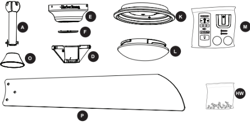
Before beginning the assembly of this product, ensure that all parts are present. Compare all parts with the package contents list and hardware contents list. If any part is missing or damaged, do not attempt to assemble the product.
Estimated Assembly Time: 120 minutes
Tools Required for Assembly (not included): Electrical Tape, Phillips Screwdriver, Pliers, Safety Glasses, Step Ladder, Wire Cutters and Wire Strippers
Helpful Tools (not included): AC Tester Light, Tape Measure and Wiring Handbook
INITIAL INSTALLATION
1. Turn off the circuit breakers and the wall switch to the fan supply line leads.

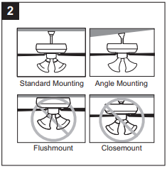
2. Determine the mounting method to use.
Standard mounting is best suited for ceilings 9 ft. or higher. For taller ceilings you may want to use a longer downrod (not included).
Angle-style mounting is best suited for angled or vaulted ceilings. A longer downrod is sometimes necessary to ensure proper blade clearance. Note:
If using the angle mount, check to ensure the ceiling angle is not steeper than 45°.
Closemount-style mounting is not available for this item.
Flushmount installation is not available for this item.
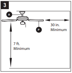
3. Ensure the blades (P) will be at least 30 in. from any obstructions. Also check the downrod (A) length to ensure the blades (P) will be at least 7 ft. above the floor.
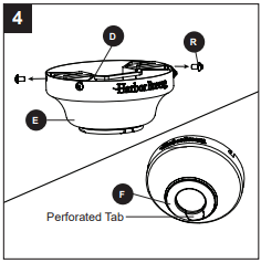
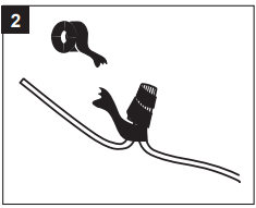
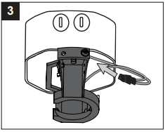
4. Loosen all four preassembled mounting bracket screws (R), then completely remove the two mounting bracket screws (R) from the round holes of canopy (E). Set aside for later use.
Detach mounting bracket (D) from canopy (E).
Note: If using this item on an angled ceiling, snap out the perforated section of the canopy cover (F).
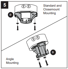
5. Attach mounting bracket (D) to outlet box (not included) using screws and washers provided with the outlet box.
CAUTION: It is very important to use the proper hardware when installing the mounting bracket (D) as this will support the fan.
Important: If using the angle mount, ensure the open end of the mounting bracket (D) is installed facing the floor.
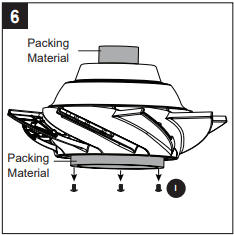
6. Remove the three fitter plate screws (I) and the packing material from the motor assembly (G). Discard the orange packing material from the top and bottom of the motor assembly (G) but save the three fitter plate screws (I) for later.
STANDARD OR ANGLE MOUNTING INSTRUCTIONS
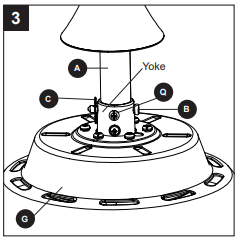
1. Remove the downrod pin (B) and downrod clip (C) from the downrod (A). Then, partially loosen the set screws (Q) in the yoke at the top of the motor assembly (G).
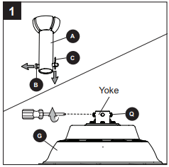
2. Insert the downrod (A) through the canopy (E) and yoke cover (O). Feed the wires from the motor assembly (G) through the downrod (A).
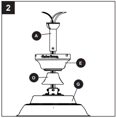
3. Slide the downrod (A) into the yoke of the motor assembly (G), align the holes, then re-install the downrod clip (C) and downrod pin (B). Secure with set screws (Q).
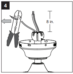
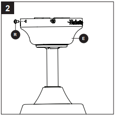
4. Depending on the length of downrod you use, you may need to cut the lead wires back to simplify the wiring. If you decide to cut back the lead wires, take the lead wires and make sure you have pulled them all the way through the top of the downrod. Measure at least 8 inches of lead wire, then cut the excess wire off with wire cutters (not included).
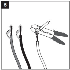
5. If you decided to cut back the lead wire in Step 4, strip 1/2 in. of insulation from the end of the white wire. Twist the stripped ends of each strand of wire within the insulation with pliers (not included). Repeat this step for black and green wires. Note: If you did not cut back the lead wires in Step 4, Step 5 is not necessary and you may proceed to Step 6.
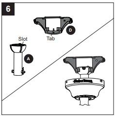
6. Install the ball end of the downrod (A) into the opening of mounting bracket (D). Align one of the four slots in the ball with the tab in the mounting bracket (D). Note: The downrod (A) should not rotate if installed correctly
WIRING
WARNING: To reduce the risk of fire, electrical shock or personal injury, wire connectors provided with this fan are designed to accept only one 12-gauge house wire and two lead wires from the fan. If your house wire is larger than 12-gauge and there is more than one house wire to connect to the two fan lead wires, consult an electrician for the proper size wire connectors to use.
CAUTION: Be sure the outlet box is properly grounded or that a ground (green or bare) wire is present.
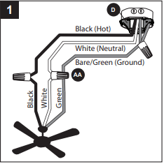
1. Secure all wiring connections with wire connectors (AA) according to the diagram and these steps:
- Connect the Bare/Green (ground) supply to Green wires from the fan and the mounting bracket.
- Connect the Black (hot) supply wire to the Black fan wire.
- Connect the White (neutral) supply wire to the White fan wire.
Note: The Black wire is hot power for the fan. The White wire is common for the fan and light kit. The Green wire is the ground wire. If household supply wires are different colors than referred to above, it is recommended a professional electrician determines the proper wiring.
Hardware Used
 Wire Connector
  x 3
x 3
2. Wrap electrical tape (not included) around each individual wire connector (AA) down to the wire.
3. Turn the spliced/taped wires upward and gently push the wires and wire connectors into the outlet box.
FINAL INSTALLATION
1. Align the canopy (E) over the loosened mounting bracket screws (R) preassembled on mounting bracket (D). Place the keyholes of the canopy (E) onto the mounting bracket screws (R) and rotate the canopy (E) clockwise.
2. Secure the canopy (E) with the mounting bracket screws (R) previously removed (Step 4, page 8). Tighten all mounting bracket screws (R) securely
3. Partially insert the blade screws (BB) along with blade washers (CC) through the blade (P) and into the blade arm (J). Tighten each blade screw (BB) with a Phillips screwdriver (not included), starting with the one in the middle. Repeat this step for the remaining blades (P) and blade arms (J).
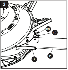
Hardware Used
 Blade Screw
  x 24
x 24
 Blade Washer
  x 24
x 24
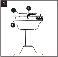
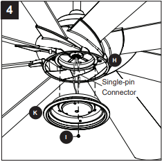
4. To install the light kit (K), connect the single-pin connector from the motor assembly (G) to the single-pin connector from the light kit (K) -- Blue to Black and White to White. Reinsert two previously removed fitter plate screws (I) (step 6, page 8) into the fitter plate (H), but do not tighten. Place the keyholes of the light kit (K) over the fitter plate screws (I) and turn clockwise. Secure the light kit (K) with the remaining previously removed fitter plate screw (I). Tighten all three fitter plate screws (I).
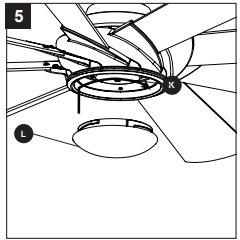
5. Lift the glass bowl (L) over the light kit (K) and turn in a clockwise direction until it is secure. CAUTION: Failure to properly secure the glass bowl, may cause the glass to fall, which could cause serious injury.
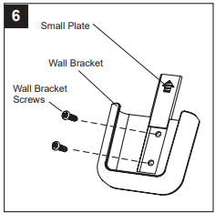
6. If desired, the mounting bracket in remote pack (M) can be installed to a wall using the provided mounting screws. The remote from remote pack (M) can be stored in the mounting bracket for easy access.
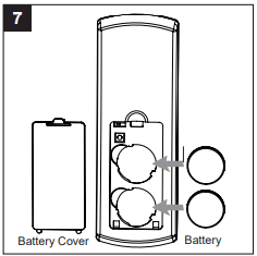
7. Remove the battery cover from the back of the remote from remote pack (M) and insert the CR2032 batteries. Replace the battery cover. If battery is installed correctly, the LED indicator on the front of the remote transmitter should illuminate when any button is pushed.
8. Turn on power supply to the fan.

Assembly is complete.
OPERATING INSTRUCTIONS
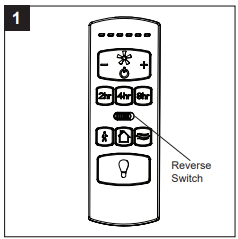
1. Using a ceiling fan will allow you to raise your thermostat setting in summer and lower your thermostat setting in winter without feeling a difference in your comfort. Note: Wait for the fan to stop before moving the reverse switch.
In warmer weather, push the reverse switch left, which will result in downward airflow creating a wind chill effect.
In cooler weather, push the reverse switch right, which will result in upward airflow that can help move stagnant, hot air off the ceiling area.
IMPORTANT: The reverse switch must be set either completely left or right in order for the fan to function correctly. If the reverse switch is set in the middle position, the fan will not operate.
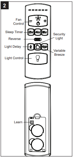
2. To operate the fan using remote control, press and release the following buttons:
(+) - Increase fan speed
(-) - Lower fan speed
( ) - Turns the fan off.
Sleep Timers: Turn off fan after 2 hours (2hr), 4 hours (4hr), or 8 hours (8hr). Light dims to confirm function is active. Press Fan On/Off to deactivate.
Light Delay - Delays turning off light for one minute which allows safe exit from room. Light dims to confirm function is active. Press Light Control button to deactivate and turn the light off.
Security Light - Press and hold Security Light button for 3 seconds to activate. Lights cycle on for 5-20 minutes and off for 60 minutes simulating occupancy. Cycle repeats continuously until disabled. Press any other button to deactivate.
Variable Breeze - Simulates a natural breeze, as if you were outside.
Light Control - Press light control to turn lights off and on. Press and hold light control to dim or brighten the lights.
Learn - For any reason, should it become necessary to reprogram the remote, follow these syncing instructions: Turn off the power at the breaker box for at least 10 seconds and then turn the power back on. Within 30 seconds, press and hold the “LEARN” button on the back of the remote for 3 seconds. The fan will turn on at low speed and light will blink once, signaling a successful synchronization.
CARE AND MAINTENANCE
At least twice each year, lower the canopy to check the downrod assembly, then tighten all screws on the fan. Clean the motor assembly with only a soft brush or lint-free cloth to avoid scratching the finish. Clean the blades with a lint-free cloth.
Battery Replacement: Use CR2032 alkaline batteries.
Total fixture wattage is 18.5 watts; do not attempt to replace LED.
Shut off the main power supply before you begin any maintenance task. Do not use water or a damp cloth to clean the fan.
TROUBLESHOOTING
The fan does not move.
1. The reverse switch is not engaged.
Firmly push the reverse switch completely left or right.
2. The wall switch is turned off.
Make sure the wall switch is turned on.
3. The power is off or the fuse (breaker) is blown.
Turn the power on or check the fuse (breaker).
4. There is a faulty wire connection.
Turn the power off and check all connections at the ceiling outlet box.
The fan is noisy
1. The blades are loose.
Check and tighten all screws that hold the fan blades to the blade arms and the motor.
2. There is a cracked blade.
Replace the cracked blade.
3. The wall control is not compatible with the fan.
Do not use a full range dimmer switch to control the fan speed.
4. The outlet box is not secure.
Ensure the outlet box is secured to the building structure.
5. The mounting bracket is not secure.
Ensure the mounting bracket is secured to the outlet box and that the screws are tight.
There is excessive wobbling.
1. The blades and/or blade arms are loose.
Check and tighten all screws that hold the fan blades to the blade arms and the blade arms to the motor.
2. The blades are unbalanced.
Switch one blade with a blade from the opposite side, or balance the fan using the blade balancing kit (N).
3.The fan mounting is not secure.
Turn off the power. Loosen the canopy and verify that the mounting bracket is secure to the electrical outlet box. The bracket must be flush without movement against the outlet box. Verify the outlet box is secure.
4. The fan is too close to the vaulted ceiling.
Use a longer downrod (sold separately) or move the fan to another location.
5. The set screws on the motor assembly yoke is loose.
Lift up the yoke cover and tighten the set screws on the yoke until secure.
The fan operates correctly, but the lights are not working.
1.The light kit wire plugs are not connected properly.
Ensure the single-pin connectors are properly secured.
2. There is a faulty wire connection.
Turn the power off and check all connections at the ceiling outlet box.
Remote control does not work.
1.Power surge may have cleared memory and remote needs to be re-synced to the receiver.
Turn off the power at the breaker box for at least 10 seconds and then turn the power back on. Within 30 seconds, press and hold the “LEARN” button on the back of the remote for 3 seconds. The fan will turn on at low speed and light will blink once, signaling a successful synchronization.
2. Battery in remote control needs to be replaced.
Insert new CR2032 batteries in battery compartment of the remote control (see page 14).
3. Interference from another remote.
If there are several fans in close proximity, turn power off to other fans and re-sync the remote (see Corrective Action 1 above).
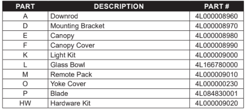
REPLACEMENT PARTS LIST
For replacement parts, call the customer service department at 1-800-643-0067, 8 a.m. - 6 p.m., EST,
Monday - Thursday, 8 a.m. - 5 p.m., EST, Friday.