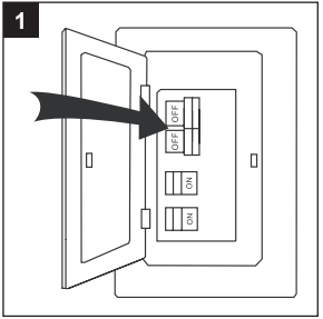
1. Turn off the circuit breakers and the wall switch to the fan supply line leads.
DANGER: Failure to disconnect the power supply prior to installation may result in serious injury or death.
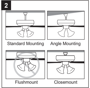
2. Determine the mounting method to use.
Standard mounting is best suited for ceilings 8 ft. or higher. For taller ceilings you may want to use a longer downrod (sold separately).
Angle mounting is best suited for angled or vaulted ceilings. A longer downrod is sometimes necessary to ensure proper blade clearance. Important: If using the angle mount, check to ensure the ceiling angle is not steeper than 16°.
Closemount-style mounting is more suitable for ceilings lower than 8 ft.
Flushmount installation is not available for this item.
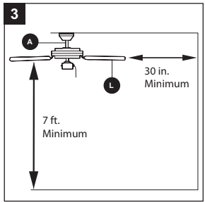
3. Ensure the blades (L) will be at least 30 in. from any obstructions. Also check the downrod (A) length to ensure the blades (L) will be at least 7 ft. above the floor.
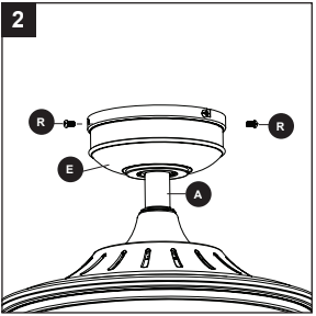
4. Loosen all four preassembled mounting bracket screws (R), then completely remove the two mounting bracket screws (R) from the round holes of canopy (E). Set aside for later use. Detach mounting bracket (D) from canopy (E).
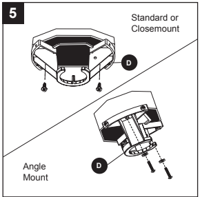
5. Attach mounting bracket (D) to outlet box (not included) using screws and washers provided with the outlet box.
Note It is very important you use the proper hardware when installing the mounting bracket (D) as this will support the fan.
Important If using the angle mount, ensure the open end of the mounting bracket (D) is installed facing the higher point of the ceiling.
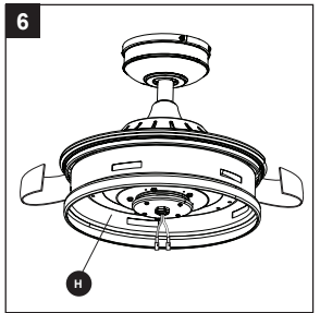
5. Remove and discard the cardboard shipping material from the motor assembly (H).
STANDARD OR ANGLE MOUNTING INSTRUCTIONS
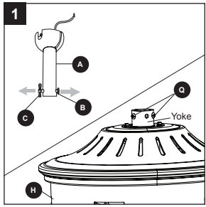
1. Remove the downrod pin (B) and downrod clip (C) from the downrod (A). Then partially loosen the set screws (Q) in the yoke at the top of the motor assembly (H).
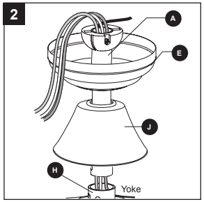
2. Insert the downrod (A) through the canopy (E) and yoke cover (J). Thread the wires from the motor assembly (H) through the downrod (A).
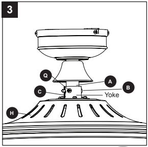
3. Slide the downrod (A) into the yoke of the motor assembly (H), align the holes, then re-install the downrod clip (C) and downrod pin (B). Secure with set the two screws (Q) and slide the yoke cover (J) down until it rests on top of the motor assembly (H).
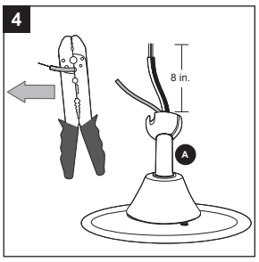
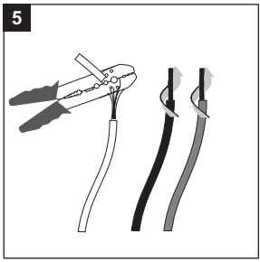
4. Depending on the length of downrod you use, you may need to cut the lead wires back to simplify the wiring. If you decide to cut back the lead wires, it is suggested you do so in the following manner: Take the lead wires and make sure you have pulled them all the way through the top of the downrod (A). Measure 8 inches of lead wire, then cut the excess wire off with wire cutters (not included).
5. If you decided to cut back the lead wire in Step 4, strip 1/2 in. of insulation from the end of the white wire. Twist the stripped ends of each strand of wire within the insulation with pliers (not included). Repeat the step for black and green wires.
Note If you did not cut back the lead wires in Step 4, Step 5 is not necessary and you may proceed to Step instead.
6. Install the ball end of the downrod (A) into the opening of the mounting bracket (D). Align the slot in the ball with the tab in the mounting bracket (D). Note: The downrod should not rotate if it is installed correctly.
DANGER: Failure to align the slot in the ball with the tab may result in serious injury or death.
Proceed to the Wiring on page 12.
CLOSEMOUNT INSTRUCTIONS
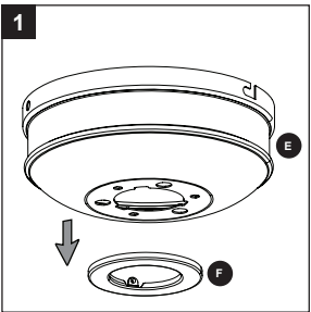
1. Remove the canopy cover (F) from the bottom of the canopy (E).
Helpful Hint: The downrod (A), yoke cover (J) and canopy cover (F) are not used in this type of installation.
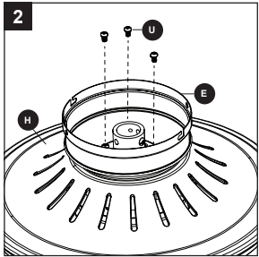
2. Remove three Phillips-head closemount screws (U) from the top of the motor assembly (H). Align the canopy (E) with the holes in the top of the motor assembly (H), then re-install the Phillips-head closemount screws (U) to secure the canopy (E) to the top of the motor assembly (H).
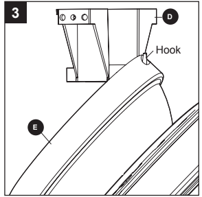
3. Raise the fan and place the canopy (E) on the hook on the mounting bracket (D).
WIRING
WARNING: To reduce the risk of fire, electrical shock, or personal injury, wire connectors provided with this fan are designed to accept only one 12 gauge house wire and two lead wires from the fan. If your house wire is larger than 12-gauge and/or there is more than one house wire to connect to the two fan lead wires, consult an electrician for the proper size wire connectors to use.
CAUTION: Be sure the outlet box is properly grounded or that a ground (green or bare) wire is present.
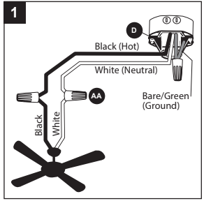
1. Connect supply and fan wires according to the diagram and these steps:
Connect the Green wires from the mounting bracket (D) to the Bare/Green (ground) supply wire.
Connect the White wire from the fan to the White supply wire.
Connect the Black wire from the fan to the Black supply wire.
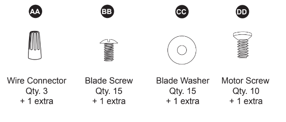
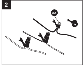
Secure all wiring connections together with wire connectors (AA).
Note: The Black wire is hot power for the fan. The White wire is common for the fan and light kit. The Green wire is the ground wire. If house wires are different colors than referred to above, stop immediately. It is recommended a professional electrician determines the proper wiring.
Hardware Used
2. Wrap electrical tape (not included) around each individual wire connector (AA) down to the wire.
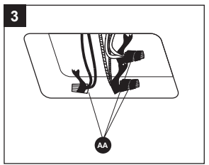
3. Turn the spliced/taped wires upward and gently push the wires and wire connectors (AA) into the outlet box.
WARNING: Ensure no bare wire or wire strands are visible after making connections. Place the Green and White wire connections on the opposite side of the outlet box from the Black
FINAL INSTALLATION
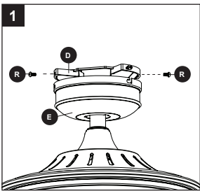
1. Align the canopy (E) over the loose mounting bracket screws (R) preassembled on mounting bracket (D). Place the keyholes of the canopy (E) onto the mounting bracket screws (R) and rotate the canopy (E) clockwise.
2. Secure the canopy (E) with the mounting bracket screws (R) previously removed (Step 4, page 8). Tighten all mounting bracket screws (R) securely.
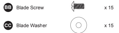
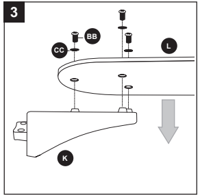
3. Partially insert three blade screws (BB) along with three blade washers (CC) through one blade (L) and into one blade arm (K). Tighten each blade screw (BB) with a Phillips screwdriver (not included), starting with the one in the middle. Repeat this step for the remaining blades (L) and blade arms (K).
Hardware Used
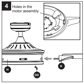
4. Insert blade arm (K) through slots in the side of the motor assembly (H). Align the holes of one blade arm (K) with two motor screw holes in underside of the motor assembly (H). Secure with two motor screws (DD). Repeat this step for the remaining blade arms (K).
Hardware Used
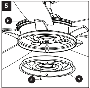
5. Remove one of the four adapter plate screws (S) from the adapter plate (I) on motor assembly (H) and loosen the other three screws. Align the screw holes of the light pan (N) with the loosened adapter plate screws (S). Replace previously removed adpater plate screw (S), then tighten all screws.
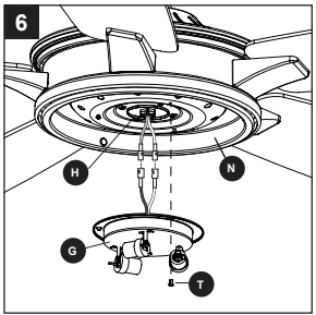
6. Remove one of the three light pan screws (T) from the light pan (N) and loosen the other two screws. Connect the wire connectors from the motor assembly (H) to the light kit (G) -- White to White and Black to Blue. Align the screw holes of the light kit (G) with the loosened light pan screws (T) and replace previously removed light pan screw (T). Tighten all screws.
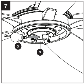
7. Install bulbs (O) into the sockets on the light kit (G).
Important Make sure you allow the bulbs (O) and light kit (G) to cool before you replace the bulbs.
8. Attach the glass shade (M) to the light pan (N) by twisting the glass shade (M) tightly in a clockwise direction.
Assembly is complete.
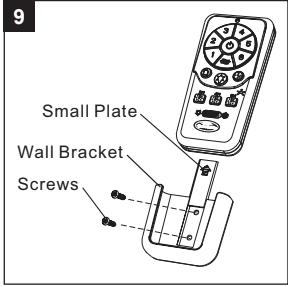
9. Remote pack (P) comes equipped with a wall bracket. If you wish to install the wall bracket, remove the small plate to expose the screw holes. Insert wall bracket screws through holes and into wall, then cover with the previously removed small plate. Remote control sits inside the wall bracket.
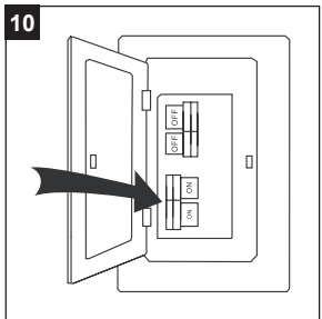
10. Turn on power supply to the fan.
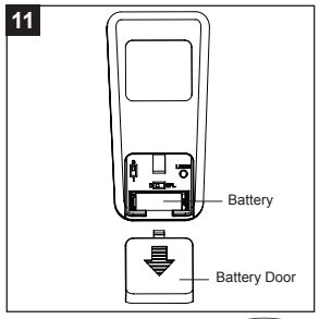
11. Remove the battery cover from the back of the remote found in remote pack (P). Insert the battery from remote pack (P) into the remote; ensure polarity of battery matches the polarity indicated in the battery compartment -- positive (+) to positive (+) and negative (-) to negative (-). Replace the battery cover and press the fan power button on the remote to ensure the LED indicator illuminates and the remote turns on the fan.
Note: If remote doesn’t turn on the fan, see TROUBLESHOOTING (page 20).
OPERATING INSTRUCTIONS
Helpful Hint: Press and hold Fan On/Off to turn off or on the sounds from the remote control.
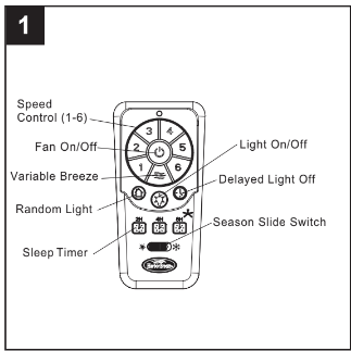
1. To operate the fan using remote control, press and release the following buttons:
Speed Control - Controls fan speed 1 (low) - 6 (high).
Fan On/Off - Turns fan off or turns fan on at most recently selected speed.
Variable Breeze - Simulates a natural breeze, as if you were outside. Press any speed control button to exit this mode.
Random Light - When button is pressed, light blinks twice to confirm Random Light mode. Lights cycle on for 5-20 minutes and off for 60 minutes. Cycle repeats continuously until any other button is pushed to discontinue Random Light mode.
Sleep Timer - Turns fan off after (2H) 2 hours, (4H) 4 hours or (8H) 8 hours.
Light On/Off - Turns light off or on.
Delayed Light Off - Delays turning off light for 1 minute which allows safe exit from room.
Season Slide Switch - Changes direction of blade rotation. For warm weather slide switch to the left and for cool weather slide switch to the right.
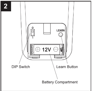
2. Remove battery door from back of the remote control (P) to access the following:
DIP Switch - Changes signal frequency if there is interference from another remote (see Troubleshooting for instructions).
Learn - Syncs remote control to receiver (see troubleshooting for instructions).
Battery Compartment - When necessary, replace the used battery with a new 12-volt battery.
CARE AND MAINTENANCE
At least twice each year, lower the canopy to check the downrod assembly, and then tighten all screws on the fan. Clean the motor housing with only a soft brush or lint-free cloth to avoid scratching the finish. Clean the blades with a lint-free cloth.
Bulb Replacement: Use 40-watt max. candelabra-base incandescent or CFL equivalent. Battery Replacement: Use a 23-amp, 12-volt alkaline battery.
Important: Shut off the main power supply before you begin any maintenance tasks. Do not use water or a damp cloth to clean the ceiling fan.
TROUBLESHOOTING
PROBLEM
POSSIBLE CAUSE
CORRECTIVE ACTION
The fan does not move.
The power is off or the fuse is blown.
There is a faulty wire connection.
The single-pin connectors are not connected properly.
The DC motor is obstructed during operation.
The power of the motor is over 8080W
Turn the power on or check the fuse.
Turn the power off. Loosen the canopy and check all connections.
Check that the single-pin connectors from the light kit and fan are connected properly.
Disable the power supply to the fan motor and re-start the motor.
The blade is overweight. Do not install the unapproved blades.
The fan is noisy.
The blades are loose.
There is a cracked blade.
The wall control is not compatible with the fan.
The outlet box is not secure.
The mounting bracket is not secure.
Check and tighten all screws that hold the fan blades to the blade arms and the motor.
Replace the cracked blade.
Do not use a full range dimmer switch to control the fan speed.
Ensure the outlet box is secured to the building structure.
Ensure the mounting bracket is secured to the outlet box and that the screws are tight.
There is excessive wobbling
The blades and/or blade arms are loose.
The blades are unbalanced.
The fan mounting is not secure.
The fan is too close to the vaulted ceiling.
The set screw in the yoke of the motor assembly is loose.
Check and tighten all screws that hold the fan blades to the blade arms and the blade arms to the motor.
Switch one blade with a blade from the opposite side. Or balance the fan using a blade balancing kit (V).
Turn off the power. Loosen the canopy and verify that the mounting bracket is secure to the electrical outlet box. The bracket must be flush without movement against the outlet box.
Use a longer downrod (sold separately) or move the fan to another location.
Lift up the yoke cover and tighten the set screw to the yoke until secure.
The fan operates correctly, but the lights are not working.
The bulbs are not installed correctly.
The light kit wire plugs are not connected properly.
There is a faulty wire connection.
Re-install the bulb(s).
Ensure the male and female plugs in the light kit are connected properly.
Turn the power off and check all connections at the ceiling outlet box.
Remote control does not work.
The power to the fan is off or the fuse is blown.
Power surge may have cleared memory and remote needs to be re-synced to the receiver.
Battery in remote control needs to be replaced.
Interference from another remote.
Turn the power on or check the fuse.
Turn power to fan off and back on. Within 30 seconds press the LEARN button on back of remote control (see p. 17).
Insert new 12V battery in battery compartment of the remote control see p. 17).
The remote control has been synced to this fan at the factory and the dip switch as been switched to “0” inside the battery compartment. If you have more than one remote control in the room, you may need to change the dip switch settings as follows: Slide the dip switch to “1” inside the battery compartment and turn the power to the fan OFF Then turn the power ON and you should hear the remote receiver make two musical sounds, indicating that the power supply is normal. Within seconds, press the “LEARN” key on the back of the transmitter. Your remote and fan should be synchronized. To verify successful synchronization, the ceiling fan light (if installed) will blink 3 times and remain ON, and the fan will rotate on HIGH speed.
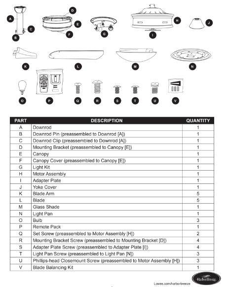
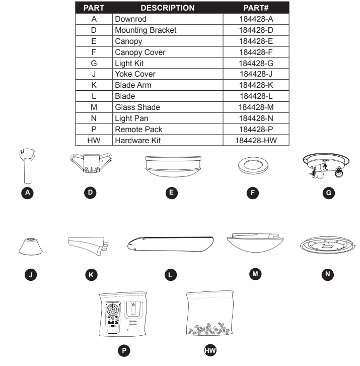
REPLACEMENT PARTS LIST
For replacement parts, call the customer service department at 1-800-643-0067, 8 a.m. - 6 p.m., EST,