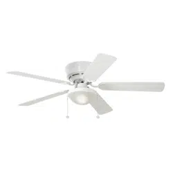
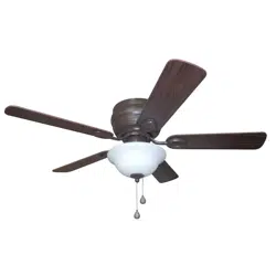
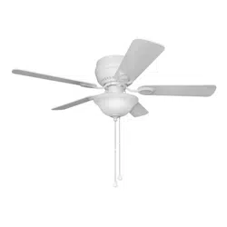
Owner's Guide Ceiling Fan
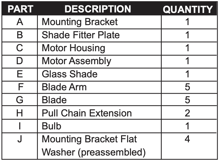
PACKAGE CONTENTS
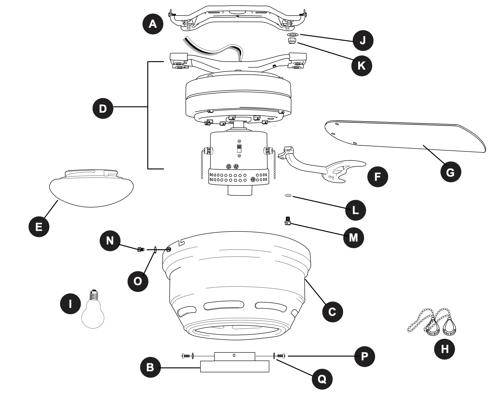
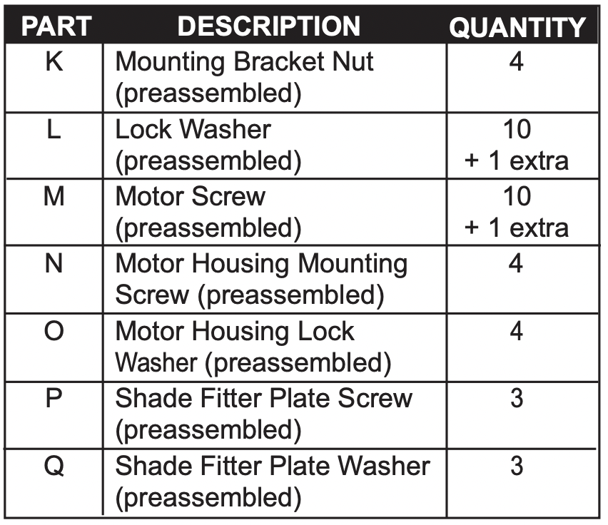
IMPORTANT REMINDER: You must use the parts provided with this fan for proper installation and safety.
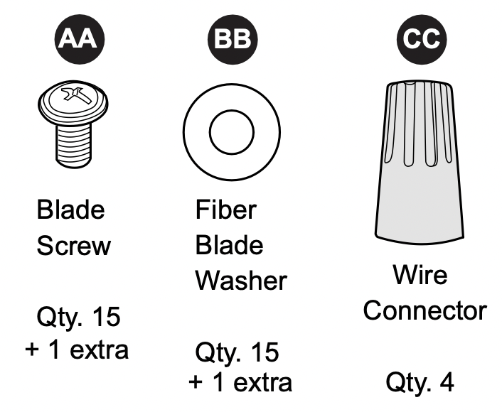
HARDWARE CONTENTS (shown actual size)
PREPARATION
Before beginning assembly of product, make sure all parts are present. Compare parts with package contents list and hardware contents list. If any part is missing or damaged, do not attempt to assemble the product.
Estimated Assembly Time: 120 minutes
Tools Required for Assembly (not included): Electrical Tape, Phillips Screwdriver, Pliers, Safety Glasses, Stepladder and Wire Strippers
Helpful Tools (not included): AC Tester Light, Tape Measure, Do-It-Yourself-Wiring Handbook and Wire Cutters
INITIAL INSTALLATION
- Turn off circuit breakers and wall switch to the fan supply line leads.
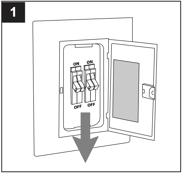
DANGER: Failure to disconnect power supply prior to installation may result in serious injury or death.
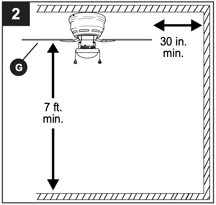
- This fan can be mounted as a flushmount on a regular (no-slope) ceiling only.
Check to make sure blades (G) will be at least 30 inches from any obstruction and at least 7 ft. above the floor.
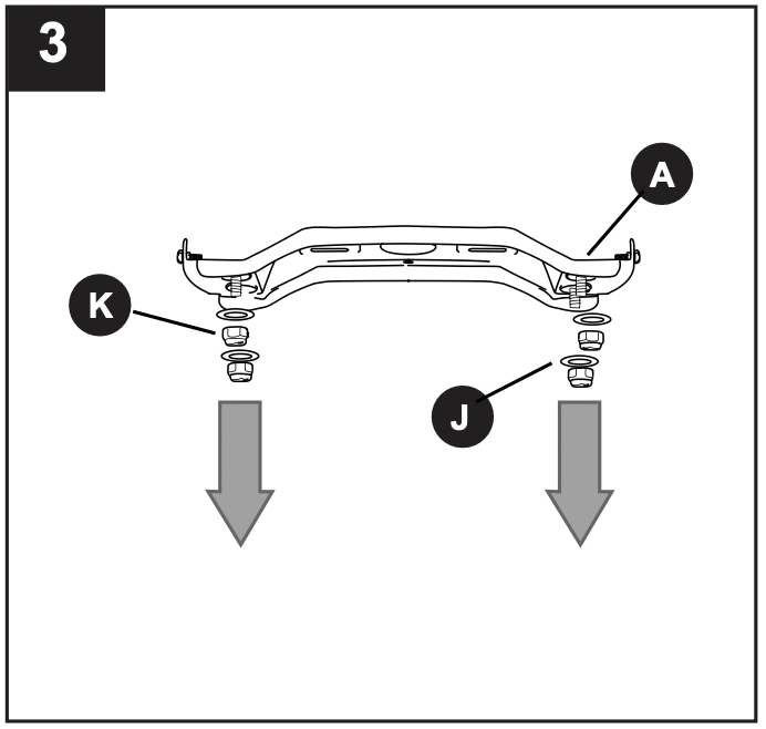
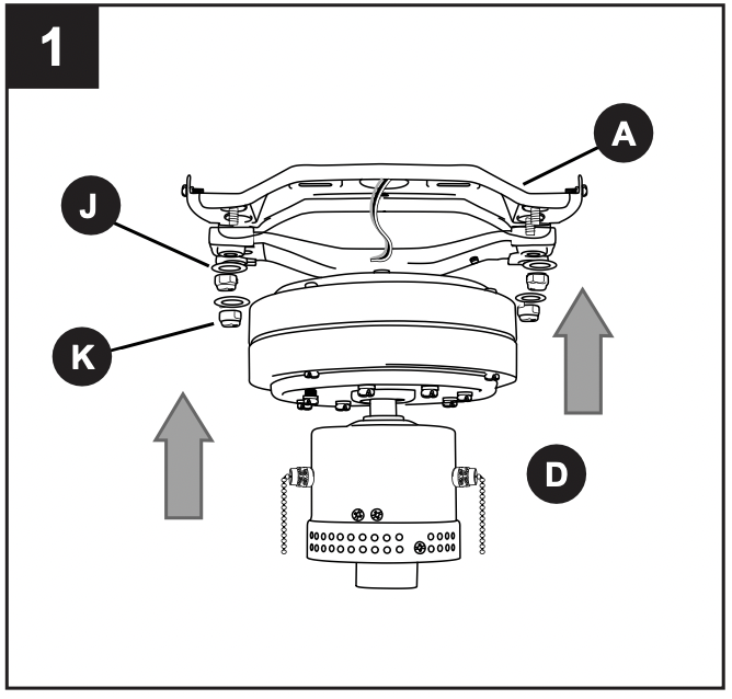
- Remove all mounting bracket nuts (K) and mounting bracket flat washers (J) from mounting bracket (A).
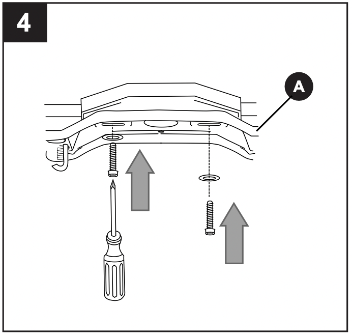
- Secure mounting bracket (A) to outlet box using screws, spring washers, and flat washers provided with the outlet box.
*Note: It is very important that you use the proper hardware when installing the mounting bracket (A) as this will support the fan.
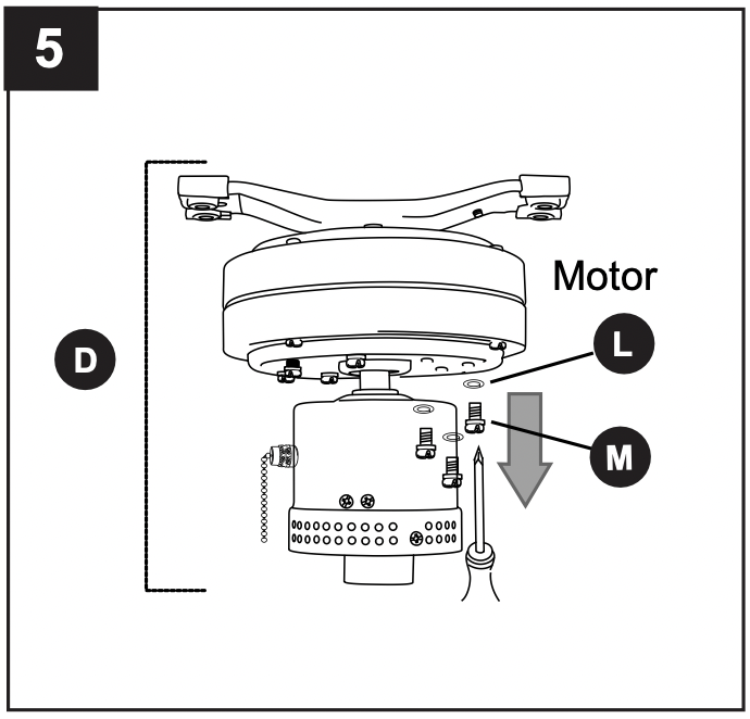
- Remove motor screws (M) and lock washers (L) from underside of motor -- save motor screws (M) and lock washers (L) to attach blade arms (F) later on. If there are also plastic motor blocks, discard them at this time.
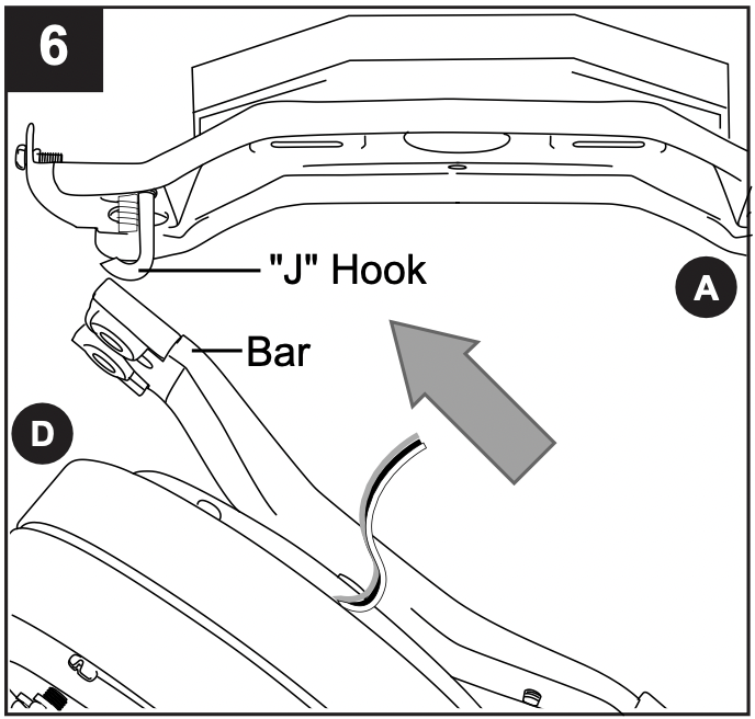
- Slide the slot in the bar at the top of the motor assembly (D) onto the "J" hook on the mounting bracket (A) to support the fan during wiring.
IMPORTANT: Do not use the end of the bar on the motor assembly (D) with the small round hole to hang the motor assembly (D) on the mounting bracket (A).
WIRING
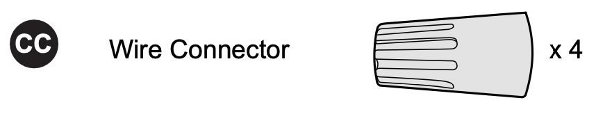
WARNING: To reduce the risk of fire, electrical shock, or personal injury, wire connectors provided with this fan are designed to accept only one 12-gauge house wire and two lead wires from the fan. If your house wire is larger than 12-gauge or there is more than one house wire to connect to the corresponding fan lead wires, consult an electrician for the proper size wire connectors to use.
CAUTION: Be sure outlet box is properly grounded and that a ground (green or bare) wire is present.
WARNING: If house wires are different colors than referred to in the following steps, stop immediately. A professional electrician is recommended to determine wiring.
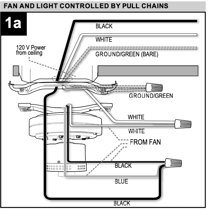
- Choose wiring diagram (Fig. 1a, Fig. 1b or Fig. 1c) that fits your situation and make appropriate wiring connections as follows: [IMPORTANT: For each wire connection below, use one of the wire connectors (CC) provided, making sure to screw wire connector (CC) on in a clockwise direction.]
1a. FAN AND LIGHT CONTROLLED BY PULL CHAINS: Connect BLACK and BLUE wire from fan to BLACK wire from ceiling. Connect WHITE wire from fan to WHITE wire from ceiling. Connect all GROUND (GREEN) wires together from fan (on motor assembly (D) and mounting bracket (A)) to BARE/GREEN wire from ceiling. (Fig. 1A)
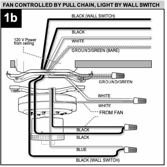
1b. FAN CONTROLLED BY PULL CHAIN, LIGHT BY WALL SWITCH: If you intend to control the fan light with a separate wall switch, connect BLACK wire from fan to BLACK wire from ceiling. Connect BLUE wire from fan to the BLACK wire from the independent wall switch for the light. Connect WHITE wire from fan to WHITE wire from ceiling. Connect all GROUND (GREEN) wires together from fan (on motor assembly (D) and mounting bracket (A)) to BARE/GREEN wire from ceiling. (Fig. 1B)
1c. FAN AND LIGHT CONTROLLED BY TWO WALL SWITCHES: If you intend to control the fan and light with separate wall switches, connect BLACK wire from fan to BLACK wire from the independent wall switch for the fan. Connect BLUE wire from fan to the BLACK wire from the other independent wall switch for the light. Connect WHITE wire from fan to WHITE wire from ceiling. Connect all GROUND (GREEN) wires together from fan (on motor assembly and mounting bracket) to BARE/GREEN wire from ceiling. (Fig. 1C)
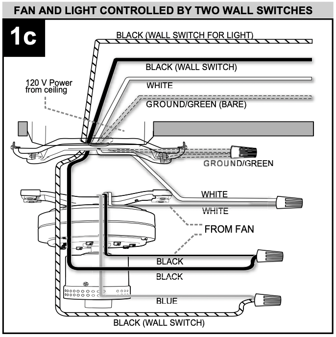
Note: BLACK wire is hot power for fan. BLUE wire is hot power for light kit. WHITE wire is common for fan and light kit. BARE/GREEN wire is ground.
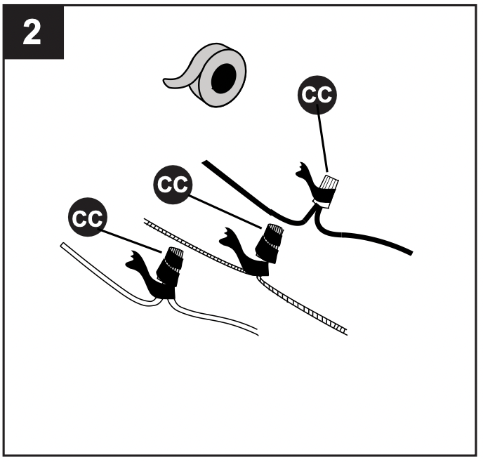
- Wrap electrical tape around each individual wire connector (CC) down to the wire.
WARNING: Make sure no bare wire or wire strands are visible after making connections. Place green and white connections on opposite side of box from the black and blue (if applicable) connections. Turn spliced/taped wires upward and gently push wires and wire connectors (CC) into outlet box.
Hardware Used
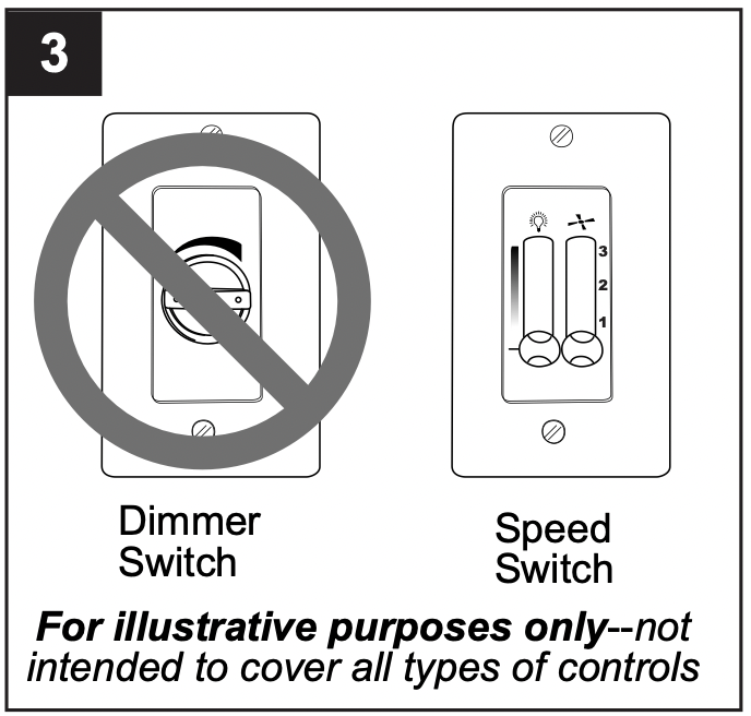
- IMPORTANT: Using a full range dimmer switch to control fan speed will cause a loud humming noise from fan. To reduce the risk of fire or electrical shock, do NOT use a full range dimmer switch to control fan speed.
FINAL INSTALLATION
- Remove motor assembly (D) from "J" hook and lift motor assembly (D) to mounting bracket (A). Align holes and secure motor assembly (D) with mounting bracket flat washers (J) and mounting bracket nuts (K) previously removed (Step 3, page 6).
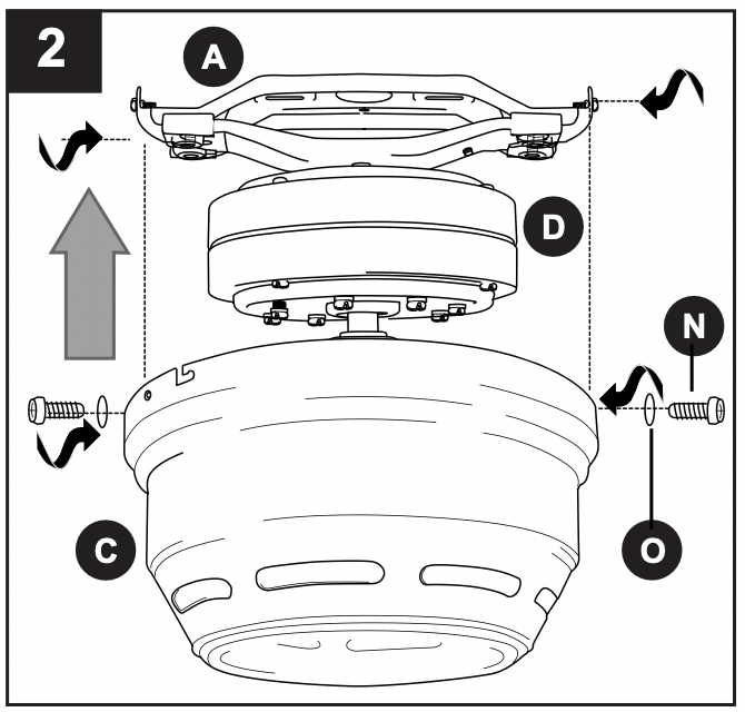
- Temporarily lift motor housing (C) to mounting bracket (A) to determine which two motor housing mounting screws (N) in sides of mounting bracket (A) align with the slotted holes in the top edge of the motor housing (C) and partially loosen these two motor housing mounting screws (N). Remove the other two motor housing mounting screws (N) and motor housing lock washers (O) from sides of mounting bracket (A). Slide motor housing (C) over motor assembly (D), aligning slotted holes in motor housing (C) with loosened motor housing mounting screws (N) in mounting bracket (A). Twist motor housing (C) to lock. Re-insert the other two motor housing mounting screws (N), along with motor housing lock washers (O), to secure motor housing (C). Tighten all motor housing mounting screws (N) securely.
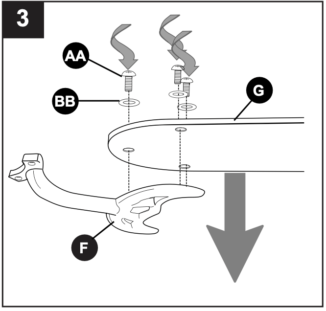
- Partially insert three blade screws (AA) along with three fiber blade washers (BB) into holes on blade arm (F) and blade (G) to attach blade arm (F) to blade (G). Then, tighten each blade screw (AA) starting with the one in the middle. Repeat with remaining blades (G).
Hardware Used
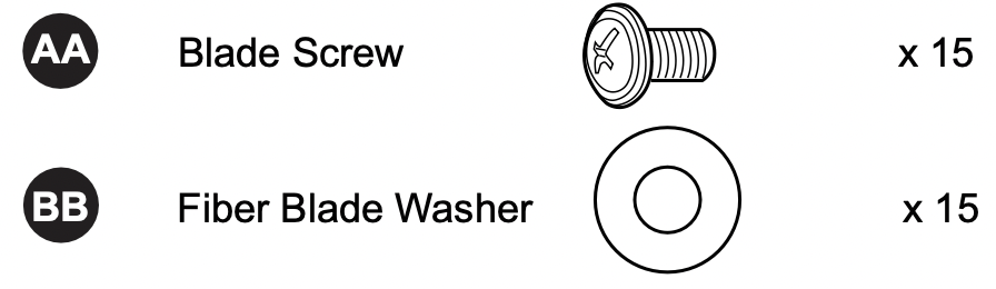
- Locate motor screws (M) and lock washers (L) removed in Step 5 on page 7.
Insert two motor screws (M) along with lock washers (L) through one blade arm (F) to attach blade arm (F) to motor. Tighten motor screws (M) securely. Repeat with remaining blade arms (F) making sure to completely secure each blade arm (F) before proceeding with the next.
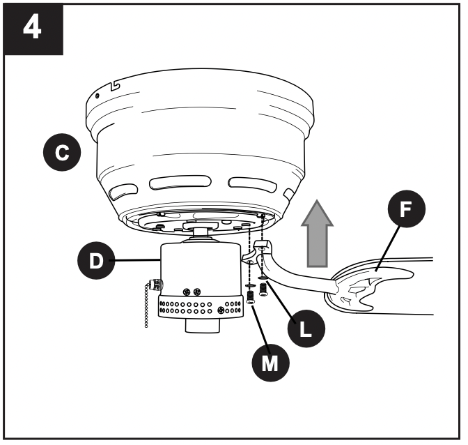
- Remove three shade fitter plate screws (P) and shade fitter plate washers (Q) from center of shade fitter plate (B). Align notch in shade fitter plate (B) with small protrusion on the inside of the light kit plate. Secure shade fitter plate (B) with the three shade fitter plate screws (P) and shade fitter plate washers (Q) that were just removed.
In order to have access to pull chains later on, thread fan and light pull chains through corresponding holes on the outer rim of the shade fitter plate (B).
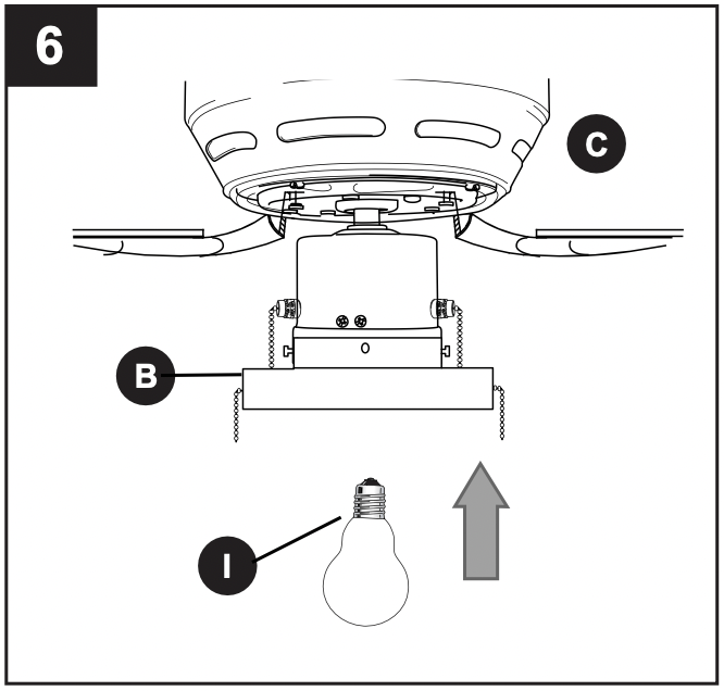
- Install bulb (I).
IMPORTANT: When you need to replace the bulb, please allow the bulb and glass shade (E) to cool down before touching the bulb or the glass shade (E).
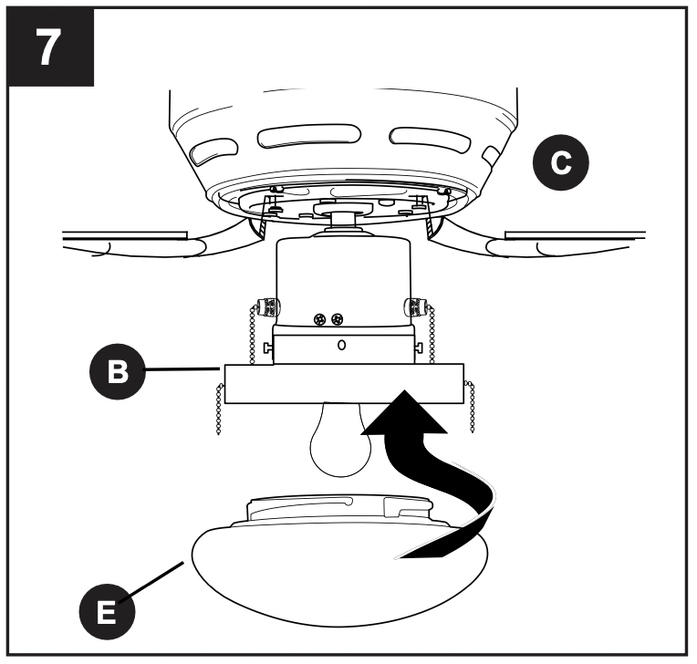
- Align slots on glass shade (E) with protrusions on the inside of the shade fitter plate (B). Turn glass shade (E) to the right (clockwise) until it no longer turns.
NOTE: Pull down gently on the glass shade (E) to make sure that it is secured completely.
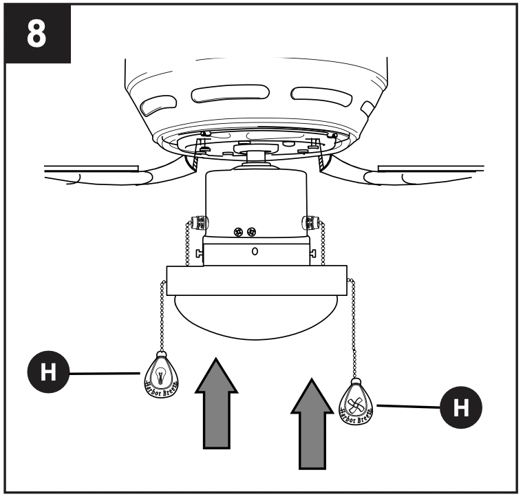
- The pull chain extensions (H) supplied in the hardware packs or custom pull chain extensions (not included) may be attached to fan and light pull chains.
OPERATING INSTRUCTIONS
- The pull chain located to the right of the reverse switch has four positions to control fan speed. One pull is HIGH, two pulls is MEDIUM, three is LOW and four turns the fan OFF.
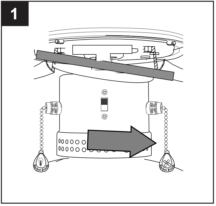
- The pull chain located to the left of the reverse switch is used to turn the light ON or OFF.
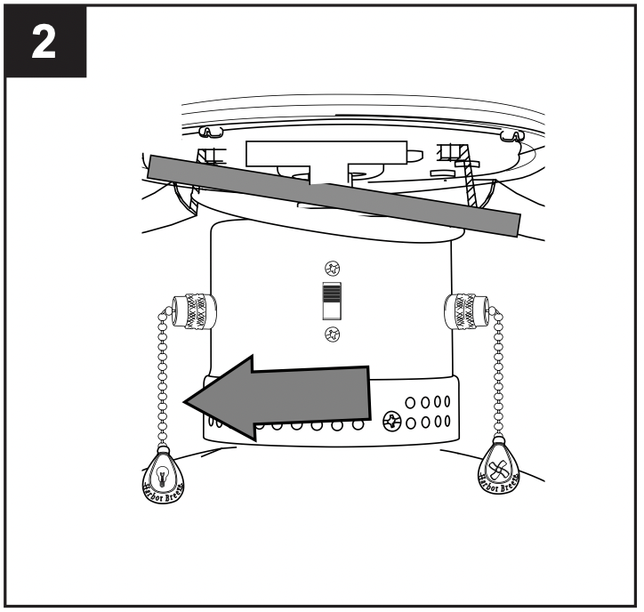
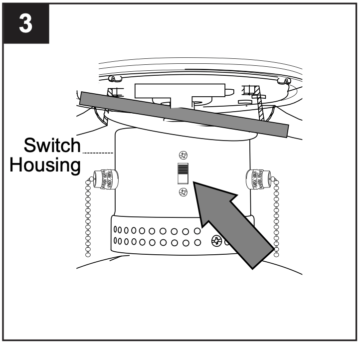
- Use the fan reverse switch, located on the switch housing, to optimize your fan for seasonal performance. A ceiling fan will allow you to raise your thermostat setting in summer and lower your thermostat setting in winter without feeling a difference in your comfort.
NOTE: Wait for fan to stop before moving the reverse switch.
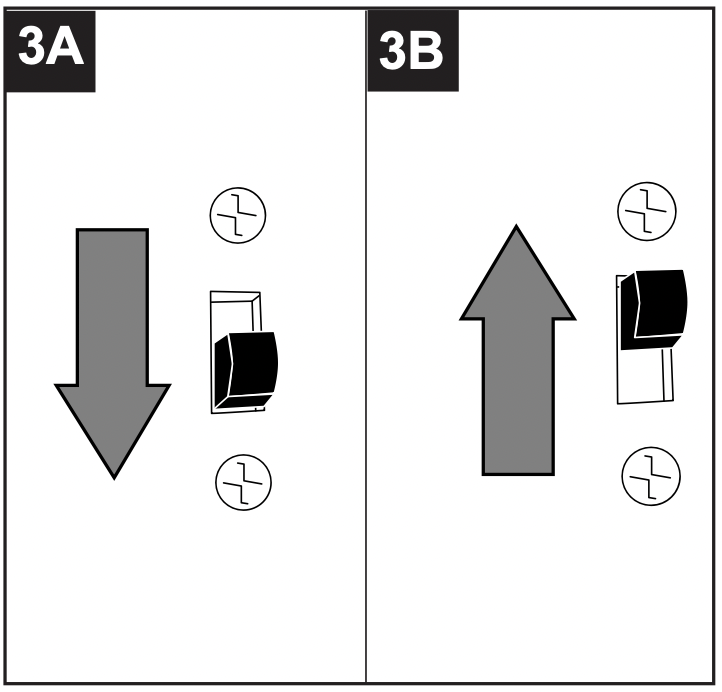
3A. In warmer weather, setting the reverse switch in the DOWN position will result in downward airflow creating a wind chill effect. (Fig. 3A)
3B. In cooler weather, setting the reverse switch in the UP position will result in upward airflow that can help move stagnant, hot air off the ceiling area. (Fig. 3B)
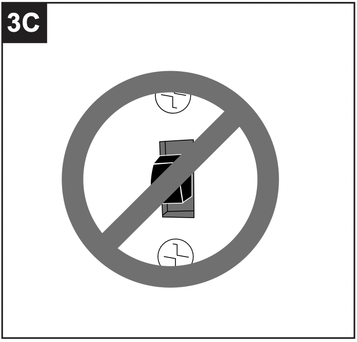
3C. IMPORTANT: Reverse switch must be set either completely UP or completely DOWN for fan to function. If the reverse switch is set in the middle position (Fig. 3C), fan will not operate.
CARE AND MAINTENANCE
At least twice each year, lower motor housing (C) to check motor assembly (D), and then tighten all screws on the fan. Clean motor housing (C) with only a soft brush or lint-free cloth to avoid scratching the finish. Clean blades (G) with a lint-free cloth. You may occasionally apply a light coat of furniture polish to wood blades for added protection.
IMPORTANT: Shut off main power supply before beginning any maintenance. Do not use water or a damp cloth to clean the ceiling fan.
Bulb Replacement: Use a standard-base 6.5-watt LED bulb or incandescent/halogen/CFL equivalent, up to 60 watts.
TROUBLESHOOTING
| PROBLEM |
POSSIBLE CAUSE
|
CORRECTIVE ACTION |
|
Fan does not move.
|
- Reverse switch not engaged.
- Power is off or fuse is blown.
- Faulty wire connection.
|
- Push switch firmly either up or down.
- Turn power on or check fuse.
- Turn power off. Loosen motor housing and check all connections.
|
|
Noisy operation.
|
- Blades are loose.
- Cracked blade.
- Full range dimmer switch.
- Fan is new.
- Motor housing is loose.
|
- Tighten all blade screws.
- Replace blade.
- Replace with an approved speed control device.
- Allow fan a "break in" period of a few days, especially when running the fan at Medium and High speeds.
- Turn power off. Carefully loosen motor housing and verify that mounting bracket is secure according to instructions on page 7.
|
|
Excessive wobbling.
|
- Blades are loose.
- Blade arms incorrectly attached.
- Unbalanced blades.
- Fan not securely mounted.
|
- Tighten all blade screws.
- Re-install blade arms.
- Switch one blade with a blade from the opposite side.
- Turn power off. Carefully loosen motor housing and verify that motor assembly is secure according to instructions on page 10.
|
|
Fan operates but light fails.
|
- Bulb not installed correctly.
- Wires in outlet box not wired properly.
- Wall switch to fan is off.
|
- Re-install bulb.
- Check wires in outlet box and, if necessary, re-wire according to instructions on pages 8 and 9.
- Make sure that wall switch to fan is on.
|
NOTE: A small amount of "wobble" is normal and should not be considered a defect.