LED Ceiling Fan
ITEM #3550513
MODEL #F-1008 BN/SIL
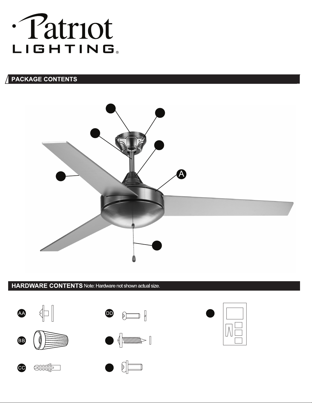
Fan Motor Assembly
x 1
Canopy
x 1
C
Downrod
x 1
D
Blades
x 3
F
Mounting Bracket
x 1
B
Flange Cover
x 1
E
Pull Chain and Fobs
x 1
E
EE
FF
Blade Screw
and Washer
x 10/13
Wire Nut
x 3
Expansion
Sleeve
x 2
5/32 Screw and
Lock Washer
x 2
Wood Screw and
Flat Washer
x 2
FF
Balance Piece
and Tape
x 3
Balance Clip
x 1
Instruction Sheet
x 1
Dual Mounting Screws
x 3
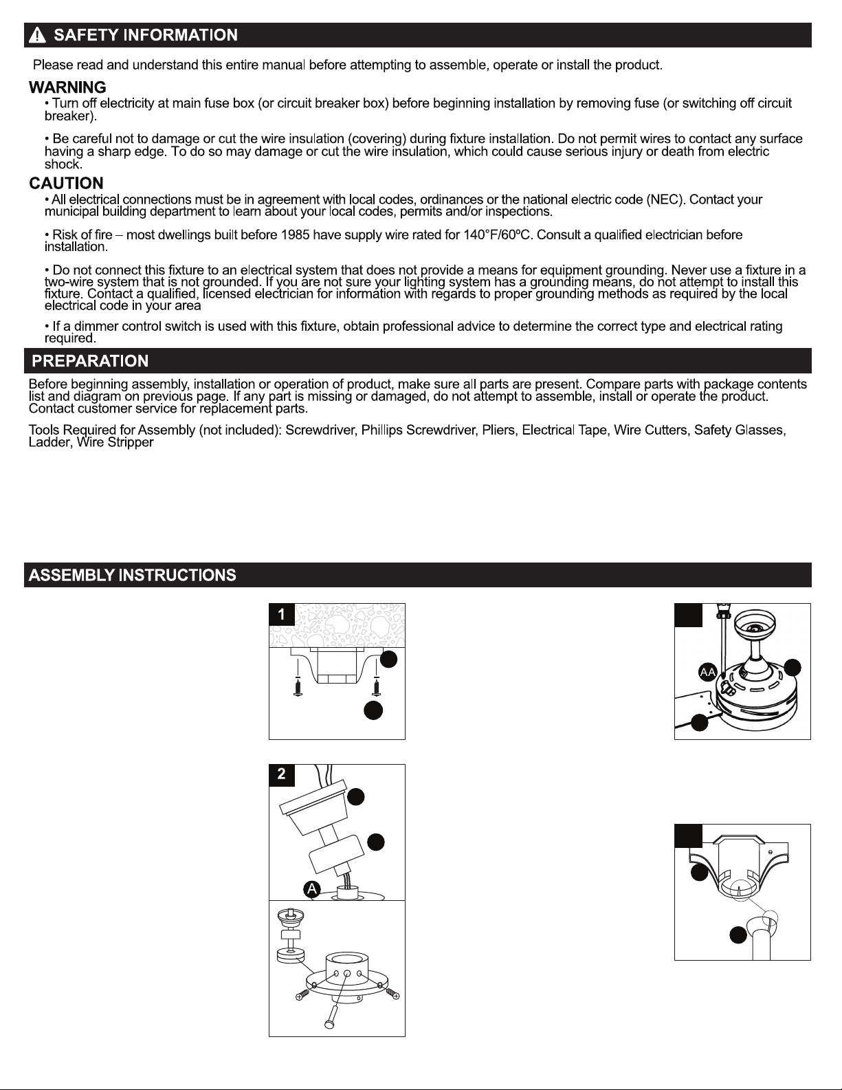
2. Loosen the two Downrod Set Screws
and remove the Clip and Connection Pin
from the downrod coupling.Insert the
Downrod through Canopy (C) and Flange
Cover (E), pull lead wires through
Downrod.
Insert Downrod into downrod coupling.
Make sure to align holes in Downrod with
the holes in the coupling. Insert the Clip
into the Connection Pin until it snaps into
place. Tighten the Screws in the downrod
coupling.
3. Remove the two screws from the
covering plate of blade-xing hole .
Insert blades (F) one at a time through slots
around the motor assembly (A) and secure
with three screws (AA) for each blade
through the top opening. Repeat this
procedure for all blades.
Replace the cover plate and secure with two
screws one all four blades have been rmly
tted .
Please ensure that the blades do not get
bent during the installation process while the
fan may be on the ground, as this will affect
the performance and balance of the fan and
this is NOT covered under warranty.
Make sure that the fan voltage (120) is compatible with your own electrical system. Check to make sure that your carton contains all the parts
mentioned in the parts list.
NOTE: The box can be used as a work space to prevent any damage on the ornamental surface.
CAUTION: Before installing, choose a location for mounting the fan where the blades have at least 7 feet of clearance from all objects and oor.
Mount an outlet box to the ceiling or use an existing box
CAUTION: Do not mount fan to sheet rock or drywall type materials. To insure proper support, use the two #1 wood screws to secure mounting
bracket to joist or beam. If the location you choose does not have a suitable support beam, install a 2"x 4" brace between ceiling joists to
support. Check to make sure blades are at least 30" from any obstruction. Check Down rod Length to make sure blades are at least 7 .1' above
the oor.
3
1. Securely attach the mounting bracket
(B) to an outlet box marked “Acceptable
for Fan Support”, using the supplied outlet
box screws with lock washers (EE)
C
F
B
A
E
EE
4. Carefully lift the fan assembly (A) onto the
Mounting Bracket (B).
Rotate the fan until the notch on the Nylon
Ball of the Downtube (A) ts against the
ridge on the Mounting Bracket (B).
With the Mounting Bracket holding the fan
assembly, follow wiring instructions.
WARNING: Failure to hold the fan assembly
may result in serious injury or death.
4
A
B
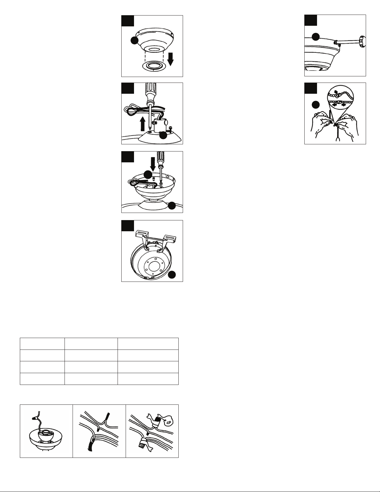
6. If necessary, remove every other screw
and lock washer from top of motor
housing. (These screws may already be in
a hardware pack.)
7. Pull wires through the canopy hole (C)
and attach canopy to motor housing using
the 3 screws and 3 lock washers (FF)
provided.
5. If using hugger mount installation,
remove rubber washer from bottom of the
canopy (C).
Note: Flange cover is not used with this
type of installation.
5
6
7
I
H
8. Temporarily hang fan onto the tab on the
mounting bracket (B) until wiring is
complete. Use one of the non-slotted
holes in the canopy (C).
When wires are matched up, connect them by twisting frayed ends
together; Screw wire connectors(3 are provided) onto the tops of the
twisted wires; Tighten them with electrical tape.
WARNING: Be sure no bare wire or wire strands are visible after
making connection. Place green and white connections on opposite
side of box from the black and blue (if applicable) connections.
8
H
9. Wiring Instructions:
IMPORTANT: If you are not sure if the e_lectrical outlet box and fan are
grounded, contact a licensed electrician for advice.They must be
grounded for safe operation. WARNING: To avoid possible electrical
shock, be sure electricity is turned off at the main fuse box before
wiring.
Your outlet box should have 3 wires. If they are not there, contact a
certied electrician to help set this part up.Match up and connect
wires from the ceiling fan to the wires from your outlet box according
to the chart below:
C
Connect with
wire connector
On fan
Ground & ground
Motor, live
Neutral & neutral
2 ground wires (green)
Motor wire (black)
Neutral wire (white)
In outlet box
Live wire (typically black)
Neutral wire (white)
Ground wire
(typically copper or green)
10. Temporarily lift canopy (C) to mounting
bracket (B) to determine which screws align
with slotted holes in canopy (C) and partially
loosen these screws. Remove the other two
screws. Raise canopy (C) to mounting
bracket (B), aligning slotted holes in canopy
(C) to lock.Insert the other two screws in
nonslotted holes. Tighten, all screws
securely.
10
C
11. Assemble decorative fob chains (E) from
hardware bag to fan and light kit pull chains.
Insert end chain into chain coupling. Check
that chains are held by lightly pulling both
chains in coupling.
11
E
Operation:
Turn fan on/off & select fan speed
Restore power to ceiling fan and test for propeer
operation.
The fan pull chain controls the fan speed settings:
1. Turn on the fan at high speed;
2. Turn on the fan at medium speed;
3. Turn on the fan at low speed;
4. Turn off the fan.
Forward and reverse direction function:
This ceiling fan is equipped with a Reverse Switch for downward or
upward air-ow.
NOTE: Do not use the Reverse Switch when the fan blades are in
motion.
Forward function
On this setting, the fan will turn counterclockwise to create a cooling
effect. Use this function during warmer weather to circulate the hot air
away from your living space.
Reverse function
On this setting, the fan will turn clockwise. Use this function during
cooler weather to re-circulate warm air.
FF
• Because of the fan's natural movement, some connections may become loose. Check the support connections, brackets and blade
attachments twice a year. Make sure they are secure.
• There is no need to oil your fan. The motor has permanently-lubricated bearings.
•Dust your fan periodically with a soft, dry cloth. Do not use harsh cleaners or materials as they may damage the unit.
•To prevent bending the blades during cleaning, support the blades so that no pressure is applied to them.
Caution!
Do not allow water to come in contact with fan blades or the ceiling fan. Doing so will create re and/ or shock hazards, damaging property.
1
one (1)
Fan Will not Start 1. Check fuse or circuit breaker and replace if necessary.
2. Turn off electrical power and check all wire connectors.
3. Check to make sure light kit and glass are installed properly and tight.
Fan Wobbles 1. Check that all blades a re sc re wed rmly into blade holders.
2. Check that all blade holders are screwed rmly into motor.
3. Check the weight of blades. All our blades a re weighed on elect ronic scales. The weight is marked on
the re verse side of the fan blade near the motor end. All of the blades should be the same weight to
prevent fan from wobbling.
4. A balancing kit is enclosed if needed.
