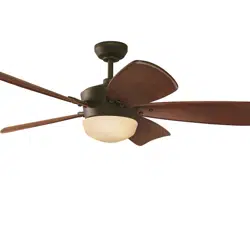
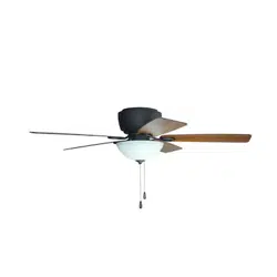
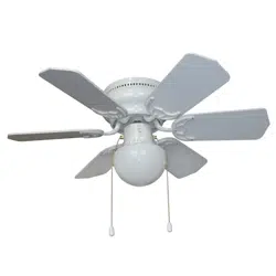
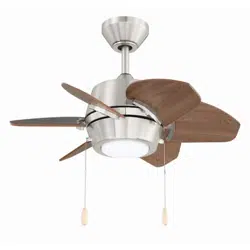
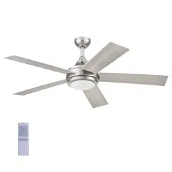
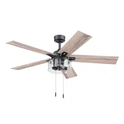
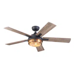
User manual Ceiling Fan
PACKAGE CONTENTS
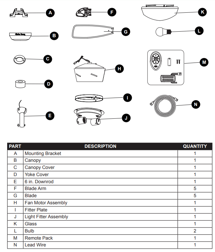
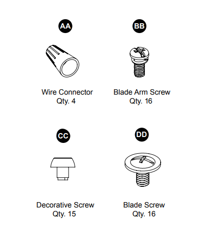
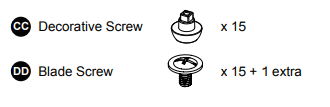
HARDWARE CONTENTS (shown actual size)
PREPARATION
- Before beginning the assembly of this product, ensure that all parts are present. Compare all parts with the package contents list and hardware contents list. If any part is missing or damaged, do not attempt to assemble the product.
- Estimated Assembly Time: 45 minutes
- TTools Required for Assembly (not included): Phillips screwdriver, step ladder, electrical tape, pliers, wire cutters, wire strippers.
- IMPORTANT NOTE: The blades must be installed before attempting to operate the fan. If the blades are not installed, the motor will not function properly
ASSEMBLY INSTRUCTIONS
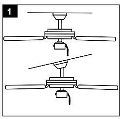
1. Determine mounting method. Downrod Mount (standard or angled ceiling) IMPORTANT: lf angle mounting, check to make sure the ceiling angle is not steeper than 20°
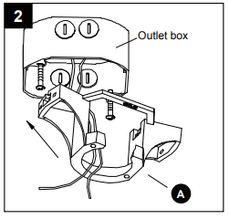
2. Install mounting bracket (A) to outlet box (not included) by sliding mounting bracket (A) over the two outlet box screws (not included). Securely tighten two outlet box screws. IMPORTANT: If angle mounting, make sure open end of mounting bracket (A) is installed facing the higher part of the ceiling.
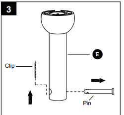
3. Remove preassembled pin and clip from downrod (E). Save for later use.
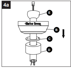
4a.STANDARD DOWNROD INSTALLATION: Insert downrod (E) through canopy (B), canopy cover (C), and yoke cover (D). Thread wires from fan motor assembly through downrod (E)
4b.EXTENDED DOWNROD INSTALLATION:
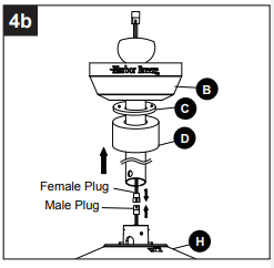
- If you are installing the fan with a longer downrod (sold separately), insert it through the canopy (B), canopy cover (C) and yoke cover (D). Then, thread lead wire (N) through the downrod and connect the MALE plug from the top of motor assembly (H) to the FEMALE plug from the lead wire (N).
- NOTE: The male plug of the lead wire (N) should extend out of the other end of the downrod.
- NOTE: The remainder of the instructions will reference downrod assembly (E), but note all of the instructions are applicable even if an accessory downrod was used.
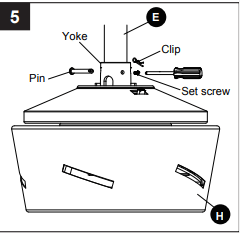
5. Loosen preassembled set screws from yoke on fan motor assembly (H). Slip downrod (E) into housing yoke, aligning holes on both parts. Insert previously removed pin through holes on yoke and downrod (E), then insert previously removed clip into pin until it snaps into place. Tighten set screws.
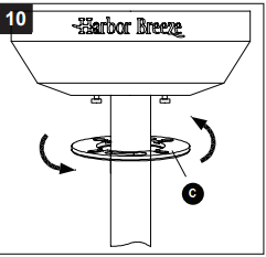
6. Install hanger ball on top of downrod (E) into mounting bracket (A) opening. Rotate fan until slot on hanger ball engages the tab on mounting bracket (A)
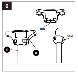
- DANGER: Be careful when aligning tab to slot. If not fully engaged, the fan could fall, which could result in serious injury or death.
- IMPORTANT: Do NOT use this fan with a dimmer switch or variable speed wall control. Using a dimmer switch or variable speed wall control will damage the fan.

7. Insert the receiver from the remote pack (M) into the mounting bracket (A) with the flat side towards the ceiling. Connect BLACK wire from receiver to BLACK wire from ceiling. Connect WHITE wire from receiver to WHITE wire from ceiling. Connect all GROUNDED (GREEN) wires together from fan to GREEN/ GROUNDED wire from ceiling. Connect the male plug from fan to female plug from the receiver together.
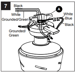
- NOTE: BLACK wire is hot power for fan and light kit. WHITE wire is common for fan and light kit. GREEN wire is grounded wire. lf house wires are different colors than referred to above, stop immediately and consult a professional electrician to determine proper wiring.
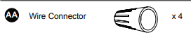
8. Twist wire ends together and screw wire connectors (AA) on in a clockwise direction. Tape wire connectors (AA) and wires together with electrical tape (not included).
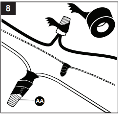
- NOTE: After making connections, make sure bare wire or wire strands are NOT visible. Place green and white connections on opposite side of box from black and blue connections. Splices should be turned upward and pushed carefully up into outlet box.
- Hardware Used
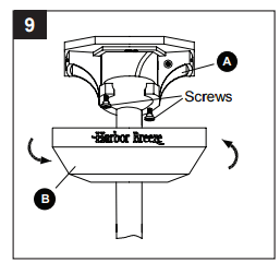
9. Slide canopy (B) up against ceiling and over two screws on mounting bracket (A). Rotate canopy (B) clockwise to lock it into place. Tighten two screws
10. Slide canopy cover (C) over two screws and rotate clockwise until it locks. NOTE: Adjust screws as necessary until canopy (B) and canopy cover (C) are snug.
11. Attach blade (G) under blade arm (F) using three decorative screws (CC) and three blade screws (DD). Repeat for remaining blades (G), blade arms (F), decorative screws (CC) and blade screws (DD).
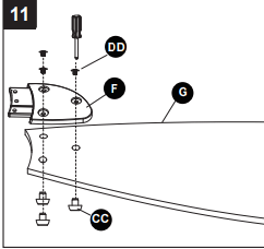
Hardware Used
12. Insert blade assembly through slot on fan motor assembly (H) and align three screw holes in blade arm (F) with screw holes in fan motor assembly (H). Secure with three blade arm screws (BB). Repeat for remaining blade assemblies.
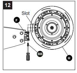
Hardware Used

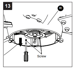
13. Loosen two preinstalled screws from fan motor assembly (H). Remove and save remaining preinstalled screw.
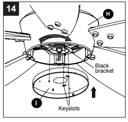
14. Pull the BLUE and WHITE wires from fan motor assembly (H) through center hole of fitter plate (I). Align two keyslots on fitter plate (I) with two screws on black bracket below fan motor assembly (H)
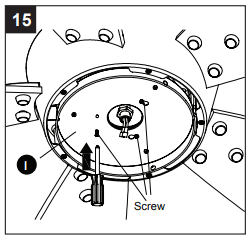
15. Place the fitter plate (I) over two screws and turn clockwise until it locks. Install previously removed screw (Step 13, page 10) and securely tighten all screws.
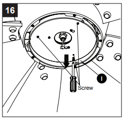
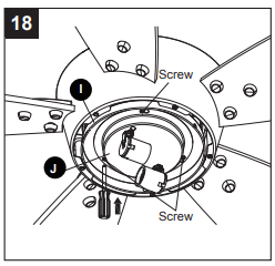
16. Loosen two preassembled screws from fitter plate (I). Remove and save remaining preassembled screw.
17. Connect BLUE wire from fan motor assembly (H) to BLACK wire from light fitter assembly (J). Connect WHITE wire from fan motor assembly (H) to WHITE wire from light fitter assembly (J).
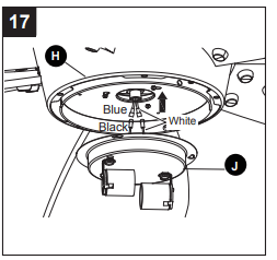
18. Align two key slots on light fitter assembly (J) with two screws on fitter plate (I). Place light fitter assembly (J) over two screws and turn clockwise until it locks. Install previously removed screw (Step 16, page 11) and securely tighten all screws.
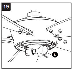
19. Install bulbs (L) into sockets.
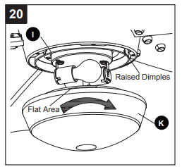
20. Place glass (K) into fitter plate (I), aligning three flat areas on top flange of glass (K) with three raised dimples in the fitter plate (I). Turn glass (K) clockwise until it stops.
OPERATING INSTRUCTIONS
REMOTE CONTROL:
NOTE: If you have more than one remote-controlled fan installed in the same location, you may want to change the frequency of the remote control to avoid any possible interference between remote controls. To change the frequency of the remote control, change the dip switch settings as described below:
1. Install Battery/Learning Process:
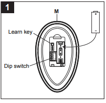
- Remove the battery cover from the back of the remote found in the remote pack (M). Insert the battery from the remote pack (M) into the remote; ensure polarity of battery matches the polarity indicated in the battery compartment: positive (+) to positive (+) and negative (-) to negative (-). Replace battery cover.
- If you need to change the dip switches in the remote control due to a potential interference issue, slide the dip switches to your choice of either up or down -- the factory setting is up. Within 30 seconds of turning the fan’s power on, press and hold the “Learn” button in the remote controls battery compartment for 1 second. Once the receiver has detected the set frequency, the downlight of the fan, if applicable, will blink twice. Replace the battery cover. To confirm the remote control and receiver have paired succesfully, press any of the fan speed control buttons on the remote control.
2. Fan Speed Control/Dimmer:
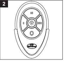
- NOTE: For the dimmer function, press and hold the light button. Light will dim. Release the light button when light is at desired level.
- NOTE: This remote control has a memory function. The receiver stores the fan speed and light setting when the fan is turned off. When the fan is turned on again, it will start with the most recent settings.
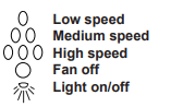
3. Reverse Switch:
- When the season changes, you may want to change the direction your fan spins. To switch between clockwise and counterclockwise rotations, flip the fan reversal switch located on the top of housing of the motor.
- WARNING: Wait for fan to stop before reversing the switch
- A. In cooler weather, clockwise rotation creates an upward airflow, which moves hot air from the ceiling into the room. Push the switch RIGHT and see a Snowflake icon for clockwise rotation.
- B. In warm weather, counterclockwise rotation creates a downward airflow, which cools the air. Push the switch LEFT and see a Sun icon for counterclockwise rotation.
CARE AND MAINTENANCE
- To reduce the risk of fire, electric shock or injury to persons, care and maintain this fan.
- IMPORTANT: Shut off main power supply before beginning any maintenance.
- Do not use water or detergents when cleaning the fan or fan blades. A dry dust cloth or lightly dampened cloth will be suitable for most cleaning.
- Clean fan housing with only a soft brush or lint-free cloth to avoid scratching the finish. Clean blades with a lint-free cloth. You may occasionally apply a light coat of furniture polish to blades for added protection.
- At least twice a year, tighten all screws and lower canopy to check mounting bracket screws and downrod assembly.
- Bulb Replacement: Use two 60-watt max medium base incandescent bulbs or LED equivalent.
TROUBLESHOOTING
| PROBLEM |
POSSIBLE CAUSE |
CORRECTIVE ACTION |
| Fan blades do not move. |
- Power is off at the breaker box or the wall switch.
|
- Turn power on at the breaker box and at the wall switch.
- Turn power off. Loosen and remove the canopy and check all wire connections.
|
| Noisy operation |
- Blades are loose.
- Cracked blade.
|
- Tighten all blade screws.
- Replace blades (call customer service).
|
| Excessive wobbling |
- The blades are loose.
- Blade arms incorrectly attached.
- The fan is not securely mounted.
- Fan too close to vaulted ceiling
|
- Tighten all blade screws.
- Reinstall blade arms.
- Turn power off. Carefully loosen the canopy and remount securely.
- Lower fan or move it to another location. Extension downrods are available at Lowes Home Improvement.
|
| Remote control malfunction |
- No flash on transmitter LED.
- The remote control doesn’t work.
|
- Replace battery.
- Please check if the battery is installed into the remote control. Make sure the battery is installed properly. One side of the battery is positive and the other is negative.
- Pair the remote control to the receiver (refer to step 1 on page 13 - “installing battery/learning process”).
|