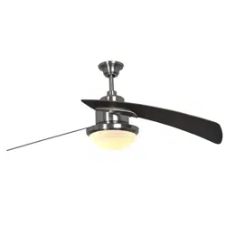
User Manual Ceiling Fan
PREPARATION
Before beginning assembly of product, make sure all parts are present. Compare parts with package contents list and hardware contents list. If any part is missing or damaged, do not attempt to assemble the product.
Estimated Assembly Time: 60 minutes
Tools Required for Assembly (not included): Phillips screwdriver, 1/4 in. fl athead screwdriver, wire strippers and step ladder
Helpful Tools (not included): AC tester light, do-it-yourself wiring handbook and wire cutters
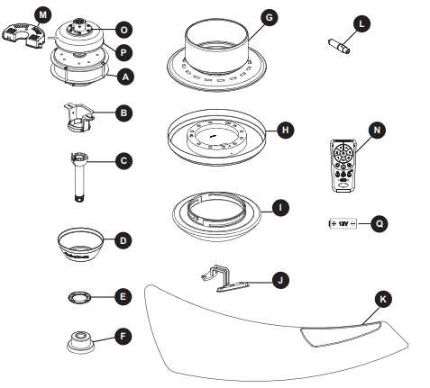
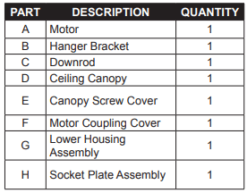
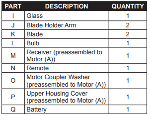
PACKAGE CONTENTS
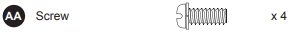
HARDWARE CONTENTS
INITIAL ASSEMBLY INSTRUCTIONS
1. Remove the two preassembled downrod support set screws (EE) on the downrod support from the motor (A). Retain the screws for later
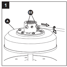
Hardware Used
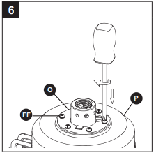
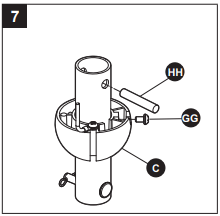
2. Remove the preassembled upper housing cover screws (FF) from the top of the motor (A). Retain these screws for later.
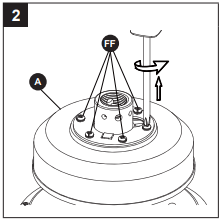
Hardware Used

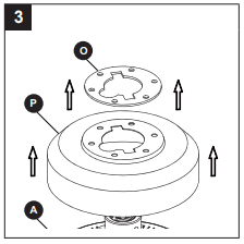
3. Remove the motor coupler washer (O) and upper housing cover (P) from the motor (A).
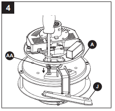
4. Position the blade holder arm (J) over the motor (A) with threaded posts showing. Make sure the bottom edge of the blade holder arm (J) is fully seated against the fl ywheel of the motor (A). Attach the screws (AA) to secure the blade holder arm (J) to the fl ywheel of the motor (A). Repeat for the other blade holder arm (J).
Hardware Used
5. Re-assemble the upper housing cover (P) and motor coupler washer (O) to motor (A).
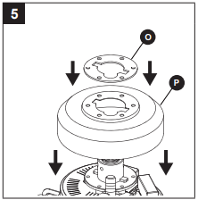
6. Secure the motor coupler washer (O) and upper housing cover (P) using the previously removed upper housing cover screws (FF). Securely tighten.
Hardware Used
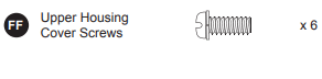
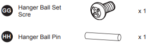
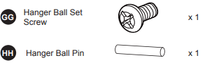
7. Loosen the preassembled hanger ball set screw (GG) until the hanger ball falls freely down the downrod (C). Remove the preassembled hanger ball pin (HH) from the downrod (C) and remove the hanger ball portion of the downrod (C). Retain the hanger ball pin (HH) and hanger ball for later
Hardware Used
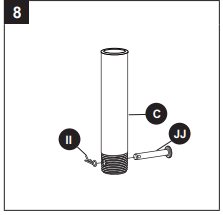
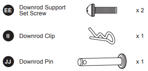
8. Remove the preassembled downrod clip (II) and downrod pin (JJ) from the bottom of the downrod (C). Retain these two parts for later.
Hardware Used
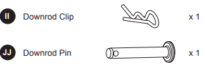
9. Route the black and white wires from the motor (A) through the downrod (C).
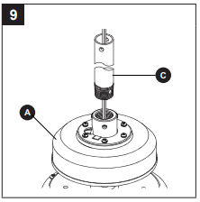
10. Thread the downrod (C) into the downrod support of the motor (A). Align the holes in the downrod support of the motor (A) with the holes in the downrod (C) and re-install the downrod pin (JJ). Secure the downrod pin (JJ) with the downrod clip (II). Re-install the two downrod support set screws (EE) and tighten securely in the downrod support of the motor (A).
Hardware Used
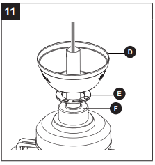
11. Route the wires through the motor coupling cover (F), canopy screw cover (E) and ceiling canopy (D).
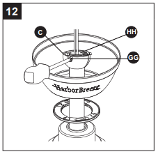
12. Route the wires through the previously removed hanger ball. Insert the previously removed hanger ball pin (HH) through the two holes in the downrod (C) and align the hanger ball so the hanger ball pin (HH) is captured in the groove in the top of the downrod (C). Pull the hanger ball up tight against the hanger ball pin (HH). Securely tighten the preassembled hanger ball set screw (GG).
Hardware Used
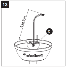
13. Cut off excess lead wire approximately 6 to 9 in. above the top of the downrod (C). Strip insulation off 1/2 in. from the end of each lead wire.
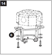
14. Securely attach the hanger bracket (B) to the outlet box (not included) using the outlet box screws and washers supplied with the outlet box
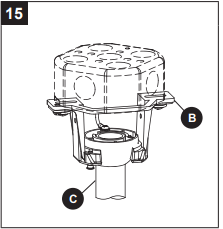
15. Carefully lift the fan assembly and seat the hanger ball of the downrod (C) on the hanger bracket (B). Be sure the groove in the ball is lined up with the tab on the hanger bracket (B).
WIRING INSTRUCTIONS
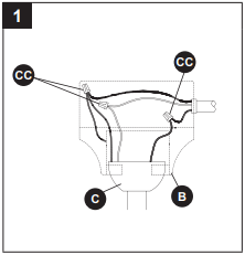
1. Connect the green grounding lead from the downrod (C) and the green grounding lead from the hanger bracket (B) to the supply grounding conductor (this may be a bare wire or wire with green colored insulation). Securely connect the wires with a wire connector (CC). Securely connect the white fan motor wire to the white supply (neutral) wire and secure the connection with a wire connector (CC). Securely connect the black fan motor wire to the black supply wire and secure the connection with a wire connector (CC).
Hardware Used
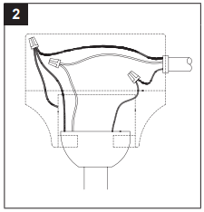
2. After connections have been made, turn the leads upward and carefully push the leads into the outlet box, with the white and green leads to one side of the box and the black leads toward the other side.
FINAL ASSEMBLY INSTRUCTIONS
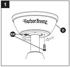
1. Remove one of the two preassembled shoulder screws (KK) in the hanger bracket (B). Loosen the second shoulder screw (KK) without fully removing it. Rotate the ceiling canopy (D) so the second shoulder screw (KK) moves into the small opening of the keyslot. Tighten the shoulder screw (KK). Re-install the previously removed shoulder screw (KK) to fully assemble the ceiling canopy (D) to the hanger bracket (B).
Hardware Used

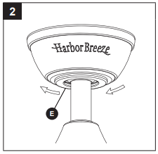
2. Securely attach and tighten the canopy screw cover (E) over the shoulder screws (KK) in the hanger bracket (B), utilizing the keyslot twist-lock feature.
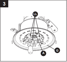
3. Remove one of the three preassembled adapter plate screws (LL) inside the adapter plate at the bottom of the motor (A). Slightly loosen the remaining two adapter plate screws (LL). Assemble the light plate assembly (G) to the adapter plate of the motor (A) using the two keyslots in the light plate assembly (G). Replace the third adapter plate screw (LL) and secure all three adapter plate screws (LL).
Hardware Used
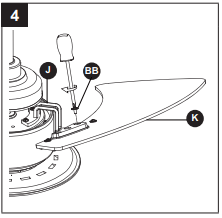
4. Place a blade (K) on the bottom of a blade holder arm (J), positioning the holes over the threaded posts. Tighten the washer-head screws (BB) to secure the blade (K) and blade holder arm (J). Repeat for the other blade (K).
Hardware Used
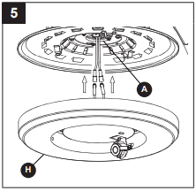
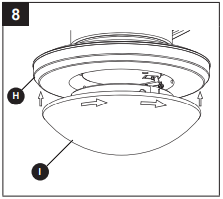
5. Connect the pin connectors from the socket plate assembly (H) to the pin connectors from the motor (A).
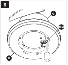
6. Remove one of the preassembled socket plate assembly screws (MM) inside the lower housing assembly (G). Assemble the socket plate assembly (H) to the lower housing assembly (G) using the two keyslots in the socket plate assembly (H). Replace the third socket plate assembly screw (MM) and securely tighten all three.
Hardware Used
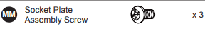
7. Install the bulb (L) into the socket.
CAUTION: Bulbs are pressurized and may shatter. DO NOT TOUCH BULBS WITH BARE HANDS. Fingerprints may result in shorter bulb life. Remove fi ngerprints with alcohol prior to use. To reduce the risk of fi re, use a 100- watt max. type T4-minican JD E11 tungsten halogen bulb. Turn off the wall switch and allow the bulb to cool for 10 minutes before relamping
8. Securely attach the glass (I) by twisting clockwise onto the socket plate assembly (H). Do not overtighten or force it.
OPERATING INSTRUCTIONS
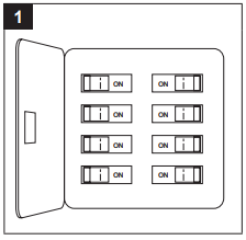
1. Restore electrical power to the outlet box by turning the electricity on at the main fuse box.
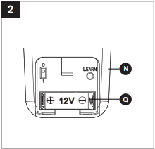
2. Remove the battery cover from the remote (N) and install the battery (Q), ensuring the polarity of the battery (Q) matches the polarity in the battery compartment. Replace the battery cover
3. Follow these steps to set the remote (N):
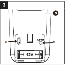
a) Slide the dip switch to “1” inside the battery compartment and turn the power to the fan OFF. Turn the power ON. The receiver (M) will make two musical sounds, indicating that the power supply is normal.
b) Within 30 seconds, press the “LEARN” key on the back of the remote (N). Your remote and fan should be synchronized.
To verify successful synchronization, the ceiling fan light will blink 3 times and remain ON, and the fan will rotate on HIGH speed.
4. Remote (N) functions:
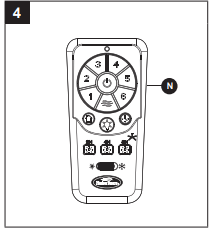
1 = Minimum speed
2 = Low speed
3 = Medium low speed
4 = Medium speed
5 = Medium high speed
6 = High speed
 = Natural breeze
Tap either of the “  /1/2/3/4/5/6 ” keys to exit natural breeze mode and shift to relative key function.
- Button:
Turns the fan off.
Press and hold the “ ” key to turn on/off the beep indicator.
 Reverse button: Controls fan direction
 Light button: Turns the light on/off. Press and hold for dimming.
 Walk Away Light Delay: Turns the fan and light off after 1 minute. During walk away light delay mode, press any other key to cancel the function
 Home Shield: The fan is turned off with the light in the A-B-A cycle. A mode: Light randomly turns on for 5-20 minutes. B mode: Light is off for 60 minutes. During home shield mode, press any other key to cancel the function
 Sleep Timer:
2H: The fan will turn off after 2 hours.
4H: The fan will turn off after 4 hours.
8H: The fan will turn off after 8 hours.
During sleep timer mode, tap the “ ” key to exit sleep timer mode.
BLADE BALANCING INSTRUCTIONS
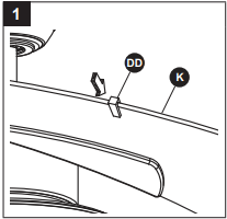
1. Interchanging positions of adjacent blades (K) can redistribute the weight and result in smoother operation. If wobble decreases, leave the blades (K) as they are. If wobble increases, switch back to the original position. Attach the balancing clip from the balance kit (DD) to the mid-point on the top edge of one blade (K).
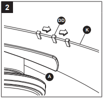
2. Run the fan at high speed (air downfl ow) and observe wobble. Repeat steps 1 and 2 for each blade (K). Note which blade (K) has the least wobble. On that blade (K), install the balancing clip (DD) to the top edge of the blade (K) near the motor (A). Start the fan and observe wobble. Stop the fan and move the balancing clip (DD) in small steps toward the end of the blade (K). At each incremental step, turn on the fan and observe the wobble. Determine the location of the balancing clip (DD) that gives the least amount of wobble.
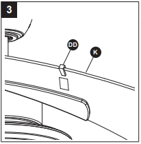
3. Peel the backing paper from one of the weighted squares in the balance kit (DD). Secure the weighted square in the balance kit (DD) fi rmly to the top of the blade (M), centered at the balancing clip location and between the edges of the blade (M). Remove the balancing clip, start the fan and observe. If the wobble still persists, repeat steps 1 through 3 with the remaining weighted squares until the wobble disappears.
CARE AND MAINTENANCE
WARNING: Do not use water when cleaning the ceiling fan. It could damage the motor or the fi nish and create the possibility of electrical shock.
- When cleaning, use only a soft brush or lint-free cloth to avoid scratching the fi nish.
- Abrasive cleaning agents are not required and should be avoided to prevent damage to the finish.
- Periodically check that all hardware is tight and secure.
- Periodic light dusting of the blades is recommended.
- Avoid using water, cleansers, or harsh rags, which can warp and ruin the finish.
- Bulb Replacement: Use 100-watt mini can-base bulb. Re-lamp with the appropriate wattage bulb.
Do not exceed the wattage indicated on the bulb socket.
TROUBLESHOOTING
The fan will not start.
1. The fuse or circuit breaker is blown.
- Check the main and branch circuit fuses or circuit breakers.
2. There are loose power line connections to the fan.
- Check the line wire connections to the fan.
3. There is a dead battery in the remote control.
- Replace with a new battery.
The fan sounds noisy.
1. The blades are not attached to the fan.
- Attach the blades to the fan before operating.
2. There are loose screws in the motor housing.
- Check to make sure all screws in the motor housing are snug (do not overtighten)
3. The screws securing the fan blade holders to the motor hub are loose.
- Check to make sure the screws that attach the fan blade holders to the motor hub are tight.
4. Wire connectors inside the housing are rattling.
- Check to make sure the wire connectors in the switch housing are not rattling against each other or against the interior wall of the switch housing.
5. There is a motor noise caused by a solid-state variable speed control.
- Some fan motors are sensitive to signals from solid-state variable speed controls. Solid-state controls are not recommended, choose an alternative control method.
6. The screws holding the blades to the blade holders are loose
The fan wobbles excessively.
1. The set screw in the downrod support is loose.
- Tighten the set screws securely in the downrod support.
2. The set screw in the in downrod/hanger ball assembly is loose.
- Tighten the set screw in the downrod/ hanger ball assembly.
3. The screws securing the fan blade holders to the motor hub are loose.
- Check to be sure the screws that attach the fan blade holders to the motor hub are tight.
4. The hanger bracket and/ or ceiling outlet box is not securely fastened.
- Tighten the hanger bracket screws to the outlet box, and secure the outlet box.
5. The fan blades are out of balance.
- Refer to Blade Balancing Instructions on page 19.
There is not enough air movement.
The downrod is too short.
- If possible, consider using a longer downrod (not included).
Please read and understand this entire manual before attempting to assemble, operate, or install the product.
- Before you begin installing the fan, disconnect the power by removing fuses or turning off circuit breakers.
- Make sure all electrical connections comply with local codes, ordinances, or the National Electrical code. Hire a qualifi ed electrician or consult a do-it-yourself wiring handbook if you are unfamiliar with installing electrical wiring.
- Make sure the installation site you choose allows a minimum clearance of 7 ft. from the blades to the floor and at least 30 in. from the ends of the blades to any obstruction.
- If you are mounting the fan to a ceiling outlet box, use a METAL octagonal outlet box.
- Secure the box directly to the building structure. The outlet box and its support must be able to support the moving weight of the fan (at least 35 lbs.). Do NOT use a plastic outlet box.
- After you install the fan, make sure all connections are secure to prevent the fan from falling.
- For supply connections, if the conductor of a fan is identifi ed as a grounded conductor, then it should be connected to a grounded conductor power supply. If the conductor of a fan is identifi ed as an ungrounded conductor, then it should be connected to an ungrounded conductor power supply. If the conductor of a fan is identifi ed for equipment grounding, then it should be connected to an equipment-grounding conductor.
- This device complies with Part 15 of the FCC Rules. Operation is subject to the following two conditions: (1) This device may not cause harmful interference, and (2) this device must accept any interference received, including interference that may cause undesired operation.
Note: This equipment has been tested and found to comply with the limits for Class B digital device, pursuant to part 15 of the FCC Rules. These limits are designed to provide reasonable protection against harmful interference in a residential installation. This equipment generates, uses and can radiate radio frequency energy and, if not installed and used in accordance with the instructions, may cause harmful interference to radio or television reception, which can be determined by turning the equipment off and on, the user is encouraged to try to correct the interference by one or more of the following measures:
– Reorient or relocate the receiving antenna.
– Increase the separation between the equipment and the receiver.
– Connect the equipment into an outlet on a circuit different from that to which the receiver is connected.
– Consult the dealer or an experienced radio/TV technician for help.
Note: For a Class A digital device, statements of 15. 105(a) must be included when appropriate for the device in question.
- The net weight of this fan is: 20.68 lbs.
WARNING:
- Do not install or use this fan if any part is damaged or missing.
- To reduce the risk of fi re, electrical shock, or personal injury, wire connectors provided with this fan are designed to accept only one 12-gauge house wire and two lead wires from the fan. If your house wire is larger than 12 gauges or there is more than one house wire to connect to the two fan lead wires, consult an electrician for the proper size wire connectors to use. Before cutting, drilling or hammering, verify their location. If needed, contact your electrician, plumber or service person.
- To reduce the risk of fi re, electric shock, or personal injury, do not bend the blade arms when installing them, balancing the blades, or cleaning the fan. Do not insert foreign objects between the rotating fan blades. Mount the fan to an outlet box marked “ACCEPTABLE FOR FAN SUPPORT” and use mounting screws provided with the outlet box. Most outlet boxes commonly used for the support of lighting fi xtures are not acceptable for fan support and may need to be replaced. Consult a qualifi ed electrician if in doubt.
- This fan is to be used in dry locations only.