Questions, problems, missing parts? Before returning to your retailer, call our customer
service department at 1-800-643-0067, 8 a.m. - 6 p.m., EST, Monday - Thursday,
8 a.m. - 5 p.m., EST, Friday.
1
ATTACH YOUR RECEIPT HERE
Serial Number ____________ Purchase Date ____________
R
Lowes.com/harborbreeze
EB13135
Harbor Breeze
®
is a registered trademark
of LF, LLC. All Rights Reserved.
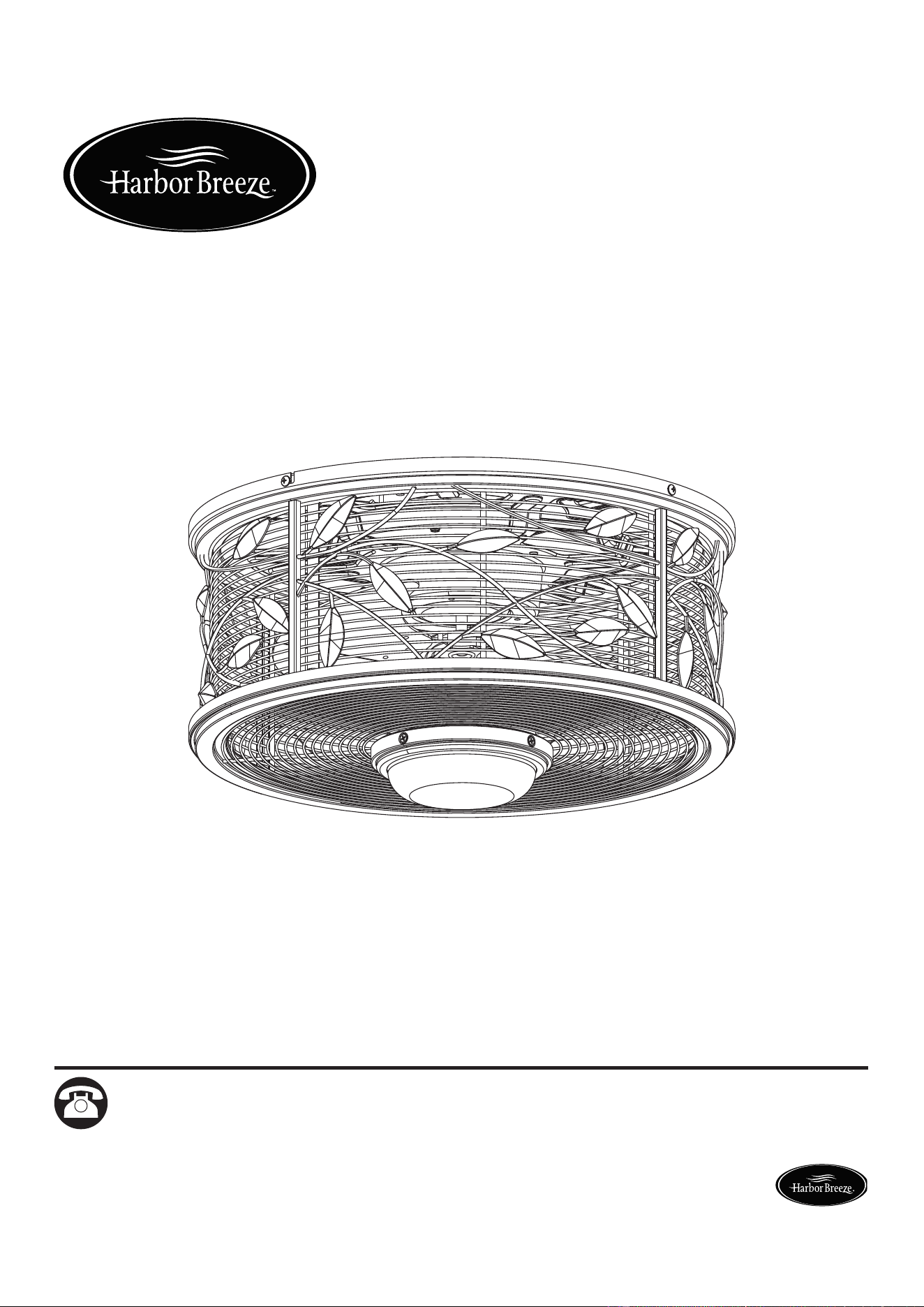
ITEM #0449504
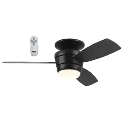
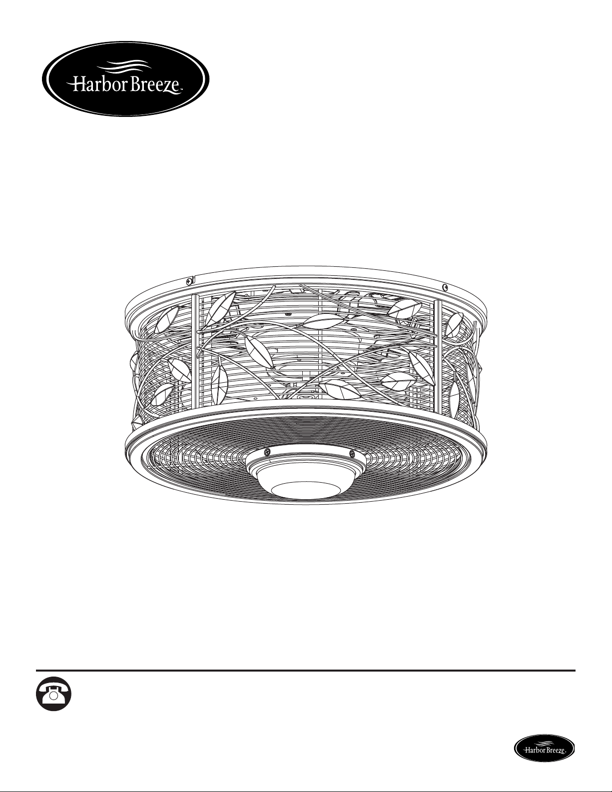
HIVE SERIES CEILING FAN
MODEL #LP8271LAZ
Español p. 16

2
Lowes.com/harborbreeze
TABLE OF CONTENTS
Package Contents . . . . . . . . . . . . . . . . . . . . . . . . . . . . . . . . . . . . . . . . . . . . . . . . . . . . . . . . . . . . . . 3
Hardware Contents . . . . . . . . . . . . . . . . . . . . . . . . . . . . . . . . . . . . . . . . . . . . . . . . . . . . . . . . . . . . . 4
Safety Information . . . . . . . . . . . . . . . . . . . . . . . . . . . . . . . . . . . . . . . . . . . . . . . . . . . . . . . . . . . . . . 4
Preparation. . . . . . . . . . . . . . . . . . . . . . . . . . . . . . . . . . . . . . . . . . . . . . . . . . . . . . . . . . . . . . . . . . . . 5
Assembly Instructions . . . . . . . . . . . . . . . . . . . . . . . . . . . . . . . . . . . . . . . . . . . . . . . . . . . . . . . . . . . 6
Remote Control Instructions. . . . . . . . . . . . . . . . . . . . . . . . . . . . . . . . . . . . . . . . . . . . . . . . . . . . . . . 8
Wiring Instructions . . . . . . . . . . . . . . . . . . . . . . . . . . . . . . . . . . . . . . . . . . . . . . . . . . . . . . . . . . . . . . 9
Final Assembly Installation . . . . . . . . . . . . . . . . . . . . . . . . . . . . . . . . . . . . . . . . . . . . . . . . . . . . . . . 10
Operating Instructions . . . . . . . . . . . . . . . . . . . . . . . . . . . . . . . . . . . . . . . . . . . . . . . . . . . . . . . . . . 12
Care and Maintenance . . . . . . . . . . . . . . . . . . . . . . . . . . . . . . . . . . . . . . . . . . . . . . . . . . . . . . . . . . 13
Troubleshooting . . . . . . . . . . . . . . . . . . . . . . . . . . . . . . . . . . . . . . . . . . . . . . . . . . . . . . . . . . . . . . . 14
Warranty . . . . . . . . . . . . . . . . . . . . . . . . . . . . . . . . . . . . . . . . . . . . . . . . . . . . . . . . . . . . . . . . . . . . . 14
Replacement Parts List . . . . . . . . . . . . . . . . . . . . . . . . . . . . . . . . . . . . . . . . . . . . . . . . . . . . . . . . . 15
3
Lowes.com/harborbreeze
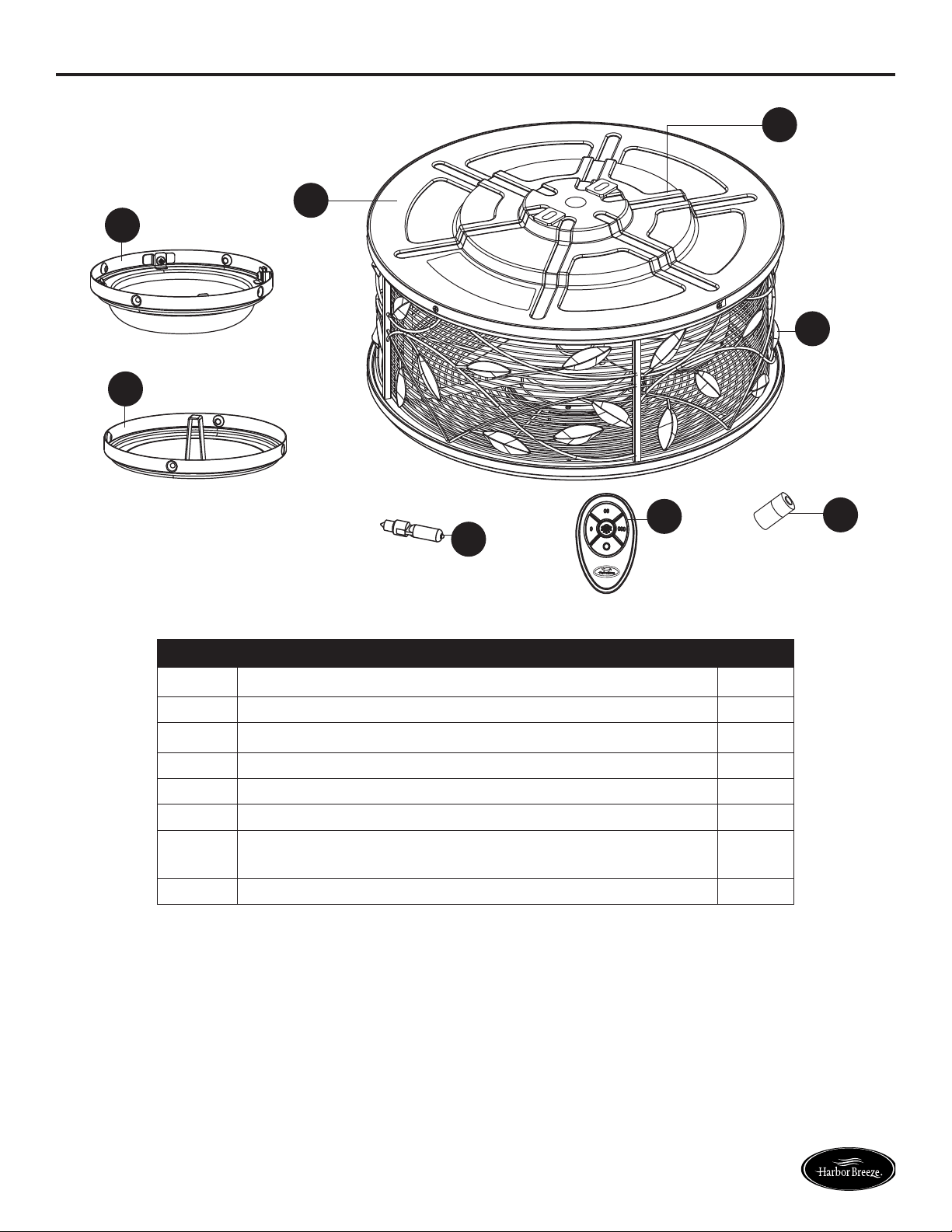
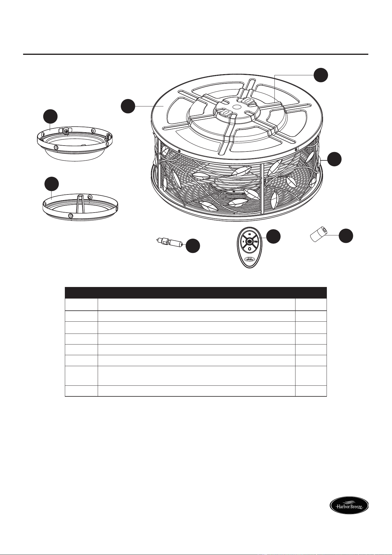
PACKAGE CONTENTS
B
G
C
D
E
A
F
H
PART DESCRIPTION QTY.
A Motor Assembly 1
B Glass 1
C Steel Cap 1
D Bulb 1
E Remote 1
F Receiver (Preassembled to Motor Assembly (A)) 1
G Ceiling Bracket (Preassembled to Motor Assembly (A)) 1
H Battery 1
4
Lowes.com/harborbreeze
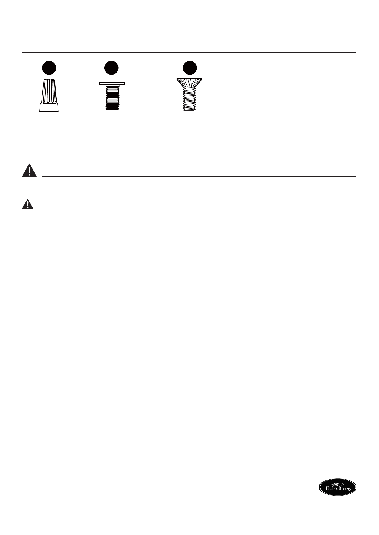
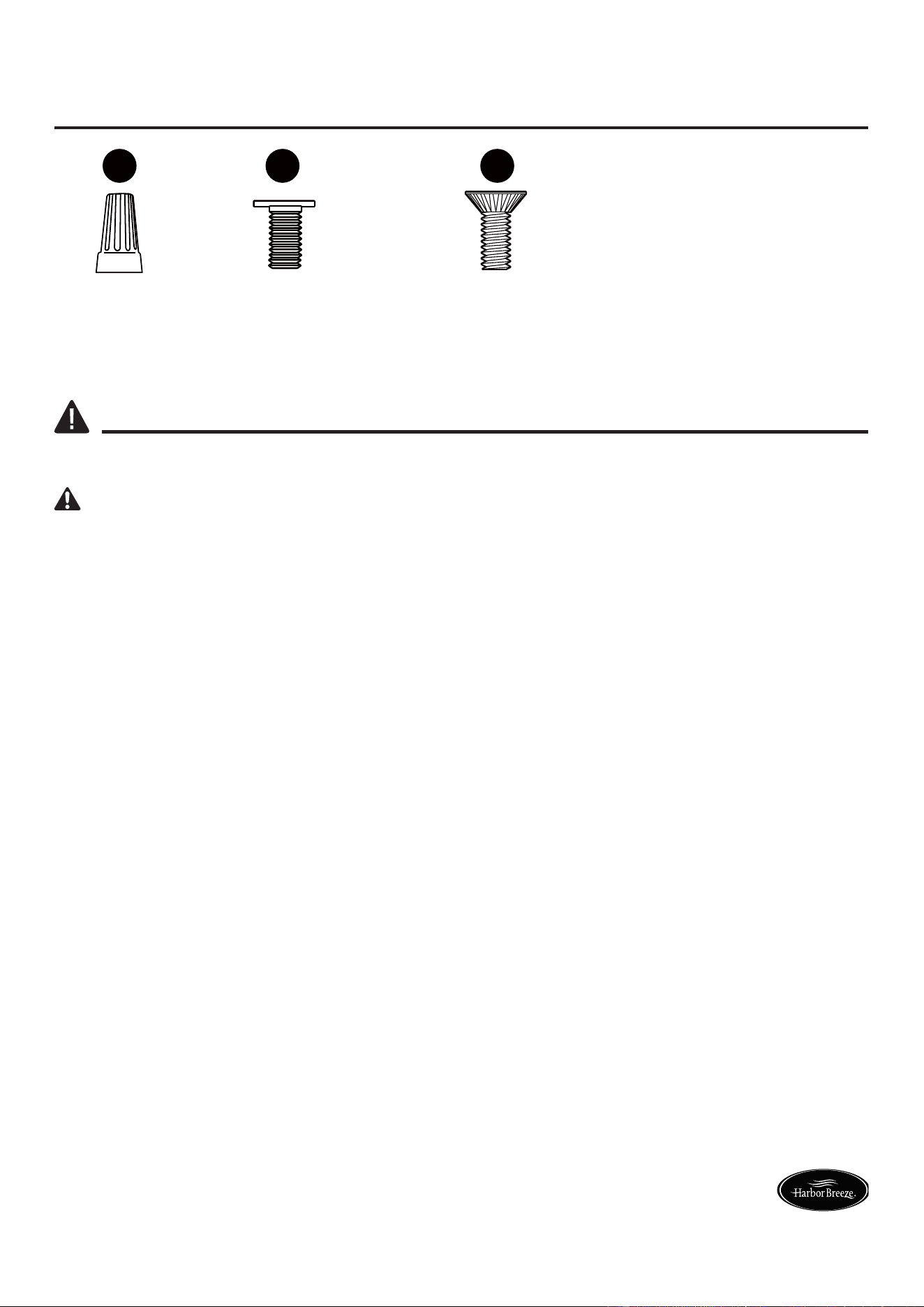
HARDWARE CONTENTS (not shown actual size)
AA
BB
CC
Wire
Connector
Qty.4
Ceiling
Bracket Screw
(Preassembled to
Motor Assembly (A))
Qty. 4
Switch Housing Screw
(Preassembled to
Motor Assembly (A))
Qty. 4
SAFETY INFORMATION
Please read and understand this entire manual before attempting to assemble, operate, or install the
product. READ AND SAVE THESE INSTRUCTIONS.
WARNING: TO REDUCE THE RISK OF FIRE, ELECTRIC SHOCK, OR INJURY TO PERSONS,
OBSERVE THE FOLLOWING:
• Before you begin installing the fan, disconnect the power by removing fuses or turning off circuit
breakers.
• Make sure all electrical connections comply with local codes, ordinances, or the National Electrical
code. Hire a qualifi ed electrician or consult a do-it-yourself wiring handbook if you are unfamiliar
with installing electrical wiring.
• If you are mounting the fan to a ceiling outlet box, use a METAL octagonal outlet box. Secure the
box directly to the building structure. The outlet box and its support must be able to support the
moving weight of the fan (at least 35 lbs.). Do NOT use a plastic outlet box.
• After you install the fan, make sure all connections are secure to prevent the fan from falling.
• For supply connections, if the conductor of a fan is identifi ed as a grounded conductor, then it
should be connected to a grounded conductor power supply. If the conductor of a fan is identifi ed
as an ungrounded conductor, then it should be connected to an ungrounded conductor power
supply. If the conductor of a fan is identifi ed for equipment grounding, then it should be connected
to an equipment-grounding conductor.
• This device complies with Part 15 of the FCC Rules. Operation is subject to the following two
conditions: (1) This device may not cause harmful interference, and (2) this device must accept any
interference received, including interference that may cause undesired operation.
• This equipment has been tested and found to comply with the limits for Class B digital device,
pursuant to part 15 of the FCC Rules. These limits are designed to provide reasonable protection
against harmful interference in a residential installation. This equipment generates, uses and can
radiate radio frequency energy and, if not installed and used in accordance with the instructions,
may cause harmful interference to radio or television reception, which can be determined by
turning the equipment off and on, the user is encouraged to try to correct the interference by one or
more of the following measures:
- Reorient or relocate the receiving antenna.
- Increase the separation between the equipment and the receiver.
- Connect the equipment into an outlet on a circuit different from that to which the receiver is
connected.
- Consult the dealer or an experienced radio/TV technician for help.

5
Lowes.com/harborbreeze
SAFETY INFORMATION
WARNING: Do not install or use the fan if any part is damaged or missing.
WARNING: To reduce the risk of fi re, electrical shock, or personal injury, wire connectors
provided with this fan are designed to accept only one 12-gauge house wire and two lead wires from
the fan. If your house wire is larger than 12 gauges or there is more than one house wire to connect
to the two fan lead wires, consult an electrician for the proper size wire connectors to use. Before
cutting, drilling or hammering, verify the wires location. If needed, contact your electrician, plumber or
service person.
WARNING: To Reduce The Risk Of Fire, Electric Shock, Or Personal Injury, Mount To Outlet Box
Marked ‘Acceptable for Fan Support of 15.9 kg (35 lbs) or less’ And Use Mounting Screws Provided
With The Outlet Box and/or Support Directly From Building Structure. Most Outlet Boxes Commonly
Used For The Support of Luminaires Are Not Acceptable For Fan Support And May Need To Be
Replaced. Consult A Qualifi ed Electrician If In Doubt.
WARNING: To reduce the risk of fi re or electric shock, do not use this fan with any solid-state
speed control device.
WARNING: This fan is to be used in dry locations only.
WARNING: Before servicing or cleaning the unit, switch power off at the service panel and lock
the service disconnecting means to prevent power from being switched on accidentally. When the
service disconnecting means cannot be locked, securely fasten a prominent warning device, such as
a tag, to the service panel.
CAUTION: Read all instructions and safety information before installing the new fan. Review
accompanying assembly diagrams.
PREPARATION
Before beginning the assembly of this product, ensure that all parts are present. Compare all parts
with the package contents list and hardware contents list. If any part is missing or damaged, do not
attempt to assemble the product.
After opening the top of the carton, remove the mounting hardware package from the foam inserts,
then remove the motor from the packaging and place it on a soft surface, such as a carpet, to avoid
damage to the fi nish.
Estimated Assembly Time: 60 minutes
Tools Required for Assembly (not included): Electrical Tape, Phillips Screwdriver, 1/4 in. Flathead
Screwdriver, Pliers, Safety Glasses, Step Ladder, and Wire Strippers
Helpful Tools (not included): AC Tester Light, Tape Measure, Wiring Handbook, and Wire Cutters
6
Lowes.com/harborbreeze
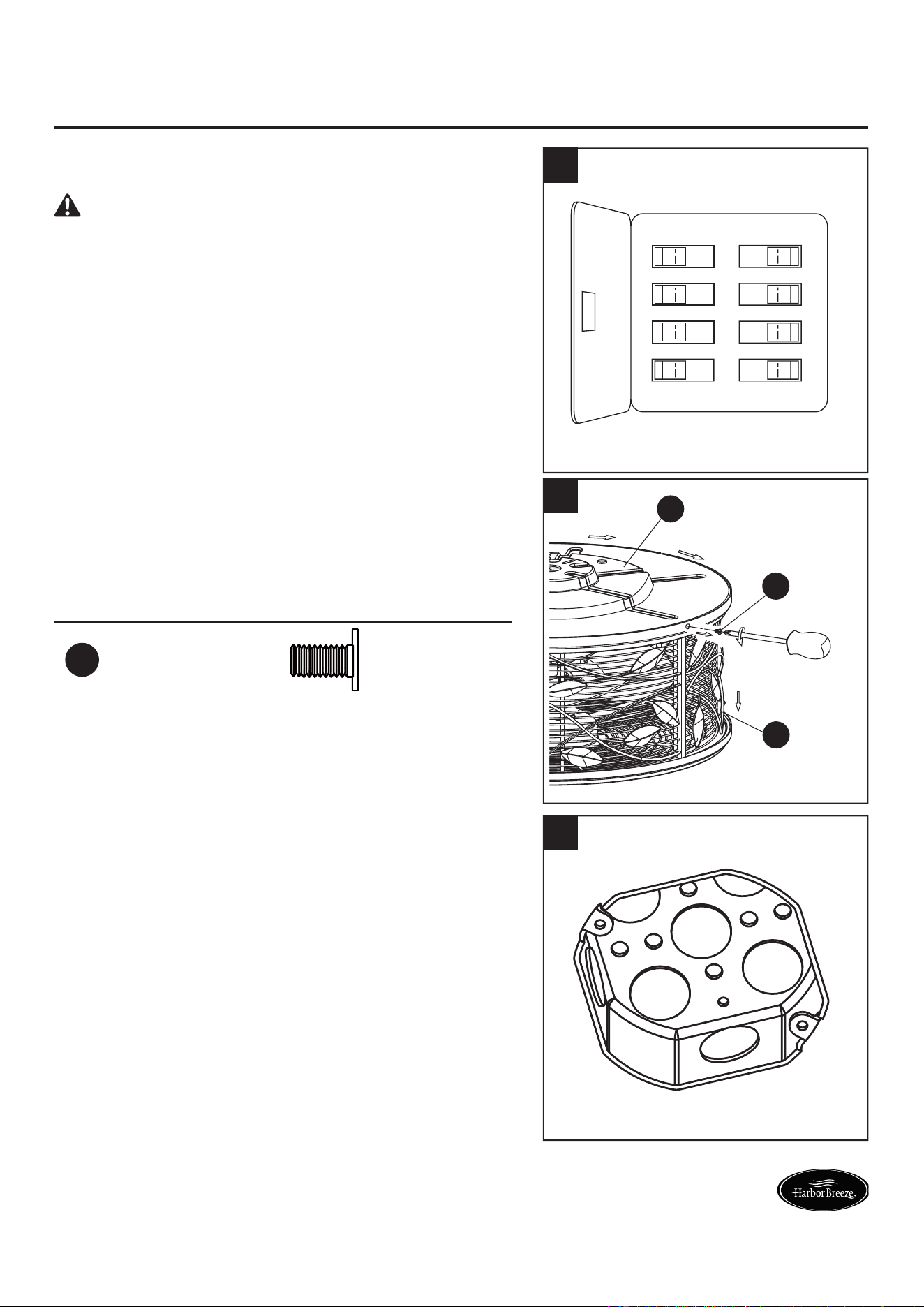
INITIAL ASSEMBLY INSTRUCTIONS
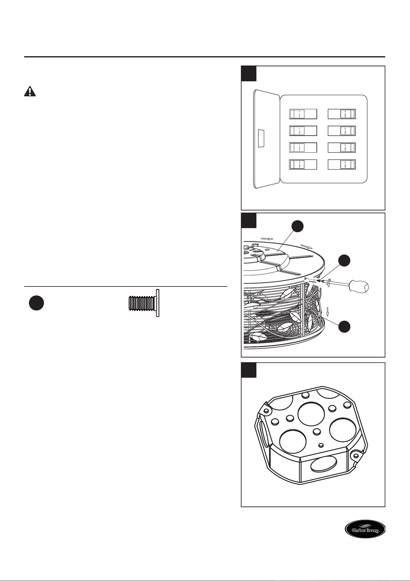
1. Turn off the electricity at the main fuse box before
assembly.
DANGER: Failure to disconnect the power supply
prior to installation may result in serious injury or death.
ON
ON
ON
ON
ON
ON
ON
ON
1
2. Separate the ceiling bracket (G) from the motor
assembly (A) by loosening the two ceiling bracket
screws (BB) in the slotted holes, then removing the
two remaining ceiling bracket screws (BB) in the
motor assembly (A). Retain the screws for later.
Hardware Used
BB
Ceiling Bracket
Screw
x 4
A
G
BB
2
3. If not done already, secure a metal octagonal outlet
box (not included) directly to the building structure.
Note: Supply wires omitted for clarity.
3
7
Lowes.com/harborbreeze
INITIAL ASSEMBLY INSTRUCTIONS
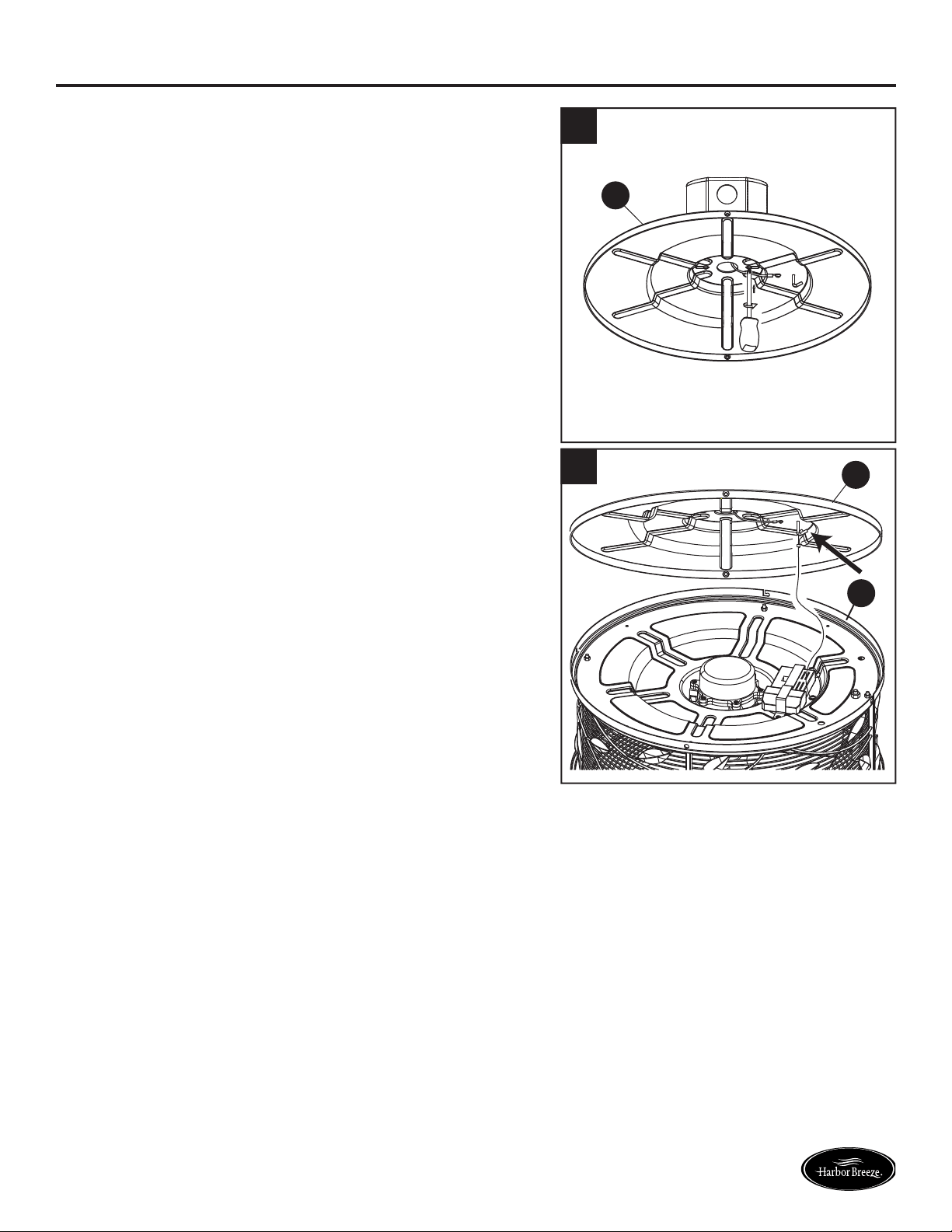
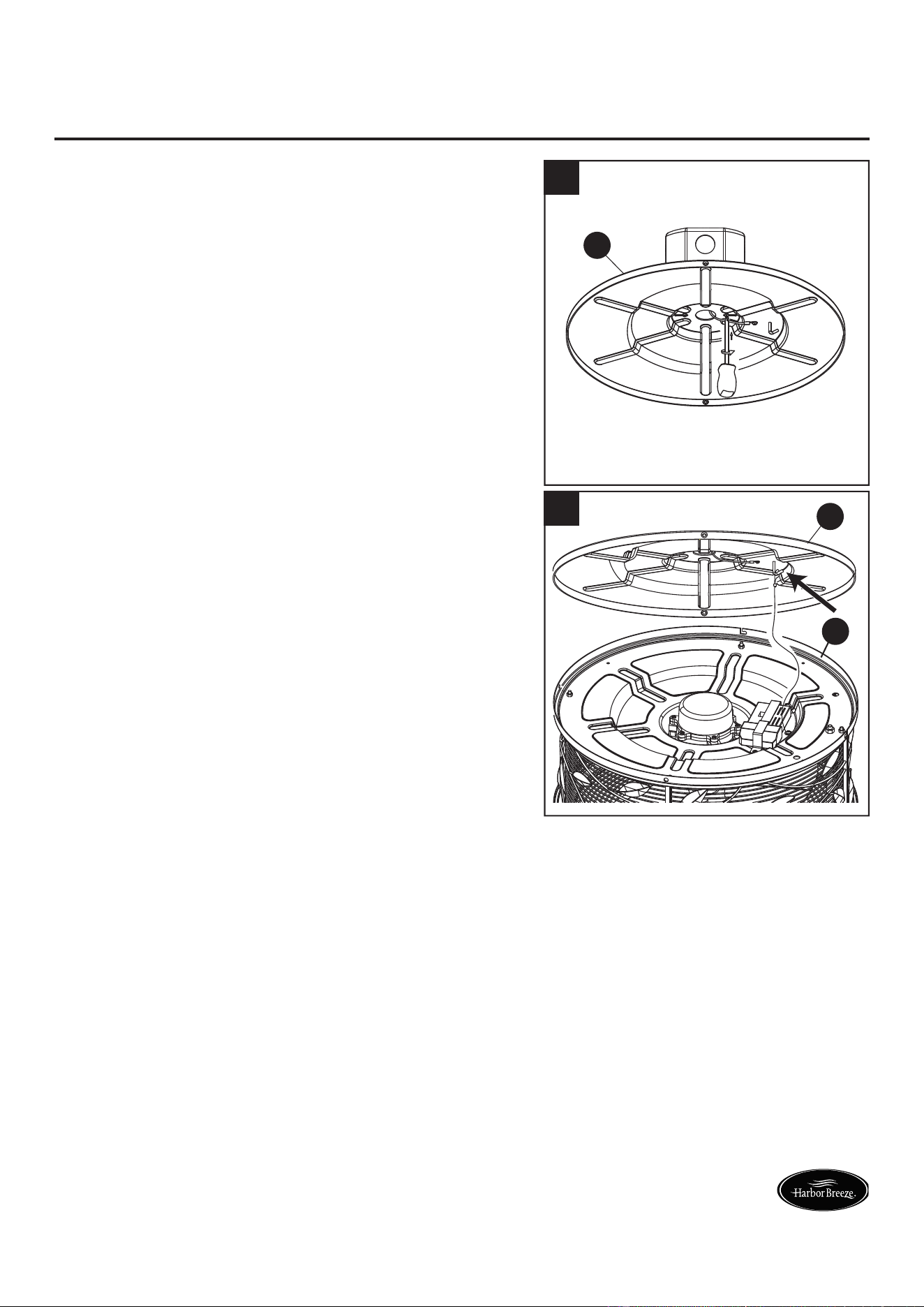
4. Securely attach the ceiling bracket (G) to the outlet
box with screws and washers supplied with the outlet
box.
G
4
5. Loop the preassembled ceiling support cable from
the motor assembly (A) over the hook on the ceiling
bracket (G).
G
A
5
8
Lowes.com/harborbreeze
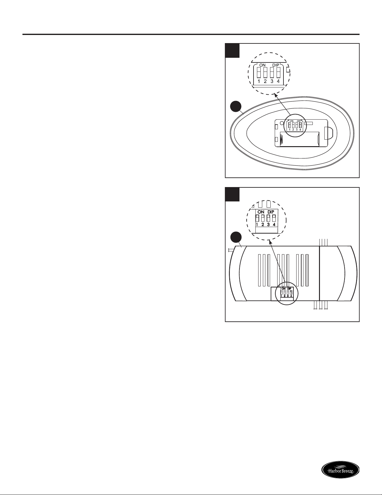
REMOTE CONTROL INSTRUCTIONS
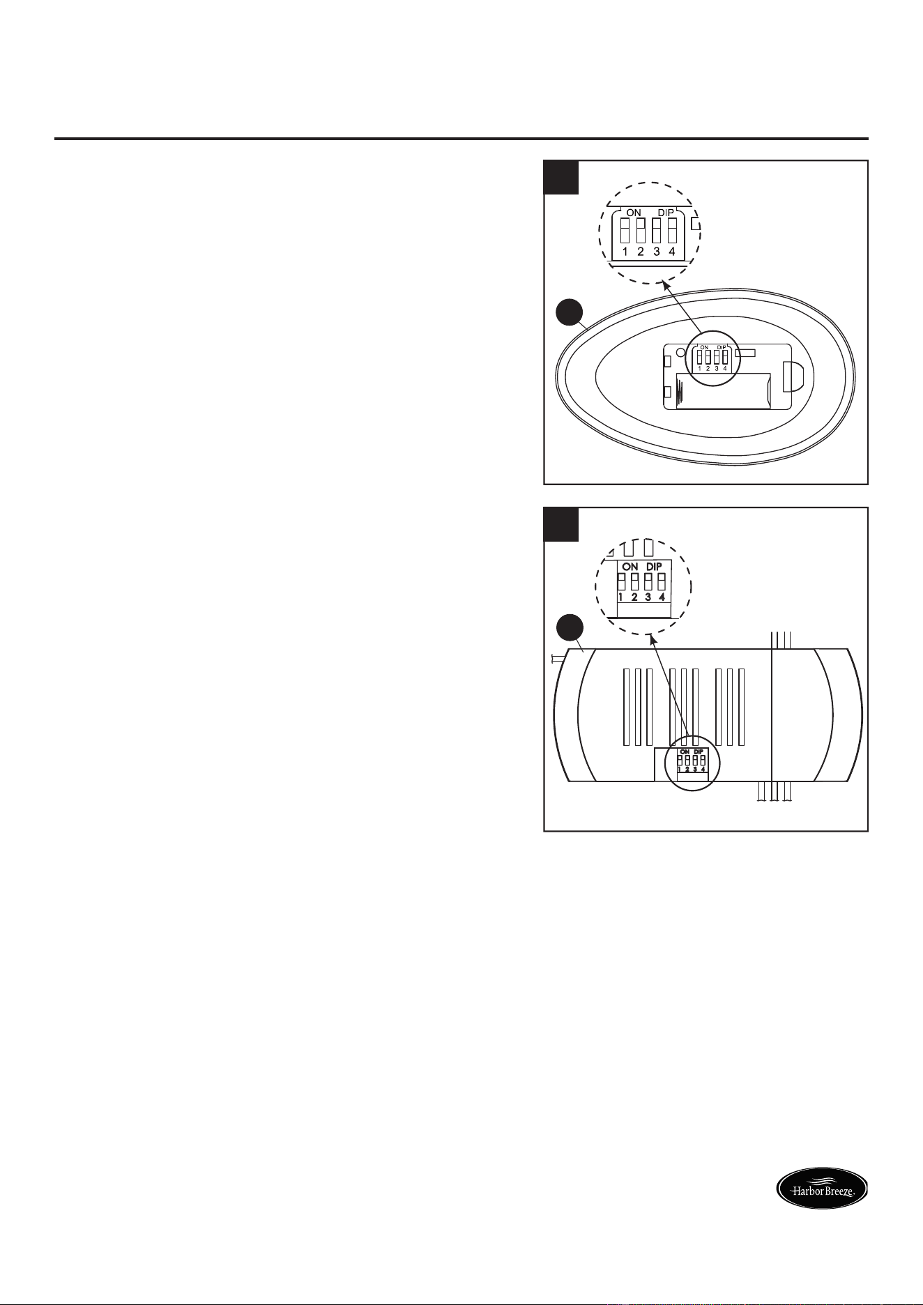
1. To set the transmitter code on the remote (E), remove
the battery cover. With a small screwdriver or a
ballpoint pen (not included), slide the code switches
up or down to a confi guration of your choice.
Note: The factory setting is all up; do not use this position.
Replace the battery cover on the remote (E).
E
1
2. Slide the code switches on the receiver (F) to the
same positions as set on the remote (E).
When two or more fans are located near each other,
set the receiver/remote for each fan to a different
code so the operation of this fan does not affect the
operation of the other fans.
Note: Before you change the code settings, make sure
the battery in the remote (E) is disconnected.
F
2
9
Lowes.com/harborbreeze
WIRING INSTRUCTIONS
Note: If you are not sure if the outlet box is grounded, contact a licensed electrician for advice, as it
must be grounded for safe operation.
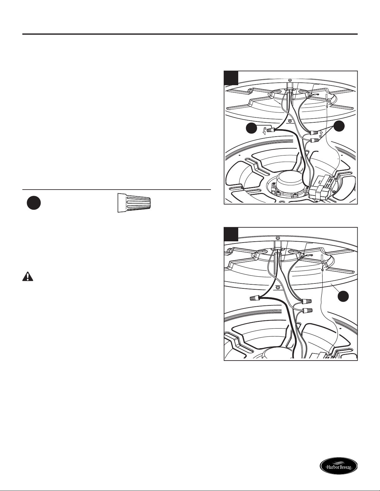
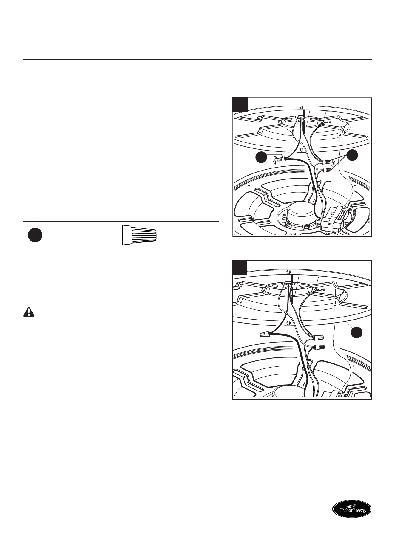
1. Connect the green grounding lead from the wire
tray and the green grounding lead from the ceiling
bracket (G) to the supply grounding conductor
(this may be a bare wire or wire with green colored
insulation). Securely connect the wires with a wire
connector (AA). Connect the white fan receiver
wire to the white supply (neutral) wire using a wire
connector (AA). Connect the black fan receiver wire
to the black supply wire using a wire connector (AA).
Hardware Used
AA
Wire
Connector
x 3
AA
AA
1
2. After connections have been made, turn leads
upward and carefully push the leads into the ceiling
bracket (G), with the white and green leads to one
side and the black leads toward the other side.
WARNING: Check to see all connections are tight,
including ground, and no bare wire is visible at the wire
connectors except for the ground wire.
G
2
10
Lowes.com/harborbreeze
FINAL ASSEMBLY INSTRUCTIONS
1. Hold the motor assembly (A) and release it from
the hook on the ceiling bracket (G). The motor
assembly (A) has two mating slots and two mating
holes. Position both slots on the motor assembly
(A) directly under and in line with the two ceiling
bracket screws (BB) in the ceiling bracket (G). Lift the
motor assembly (A), allowing the two ceiling bracket
screws (BB) to slide into the mating slots. Rotate
the motor assembly (A) until both ceiling bracket
screws (BB) drop into the slot recesses on the motor
assembly (A). Tighten the ceiling bracket screws
(BB) securely. Then, install the previously removed
ceiling bracket screws (BB) into the remaining mating
holes of the ceiling bracket (G) to secure the motor
assembly (A) to the ceiling bracket (G).
Hardware Used
BB
Ceiling Bracket
Screw
x 4
G
BB
A
1
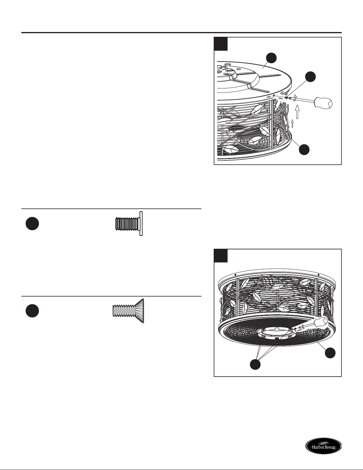
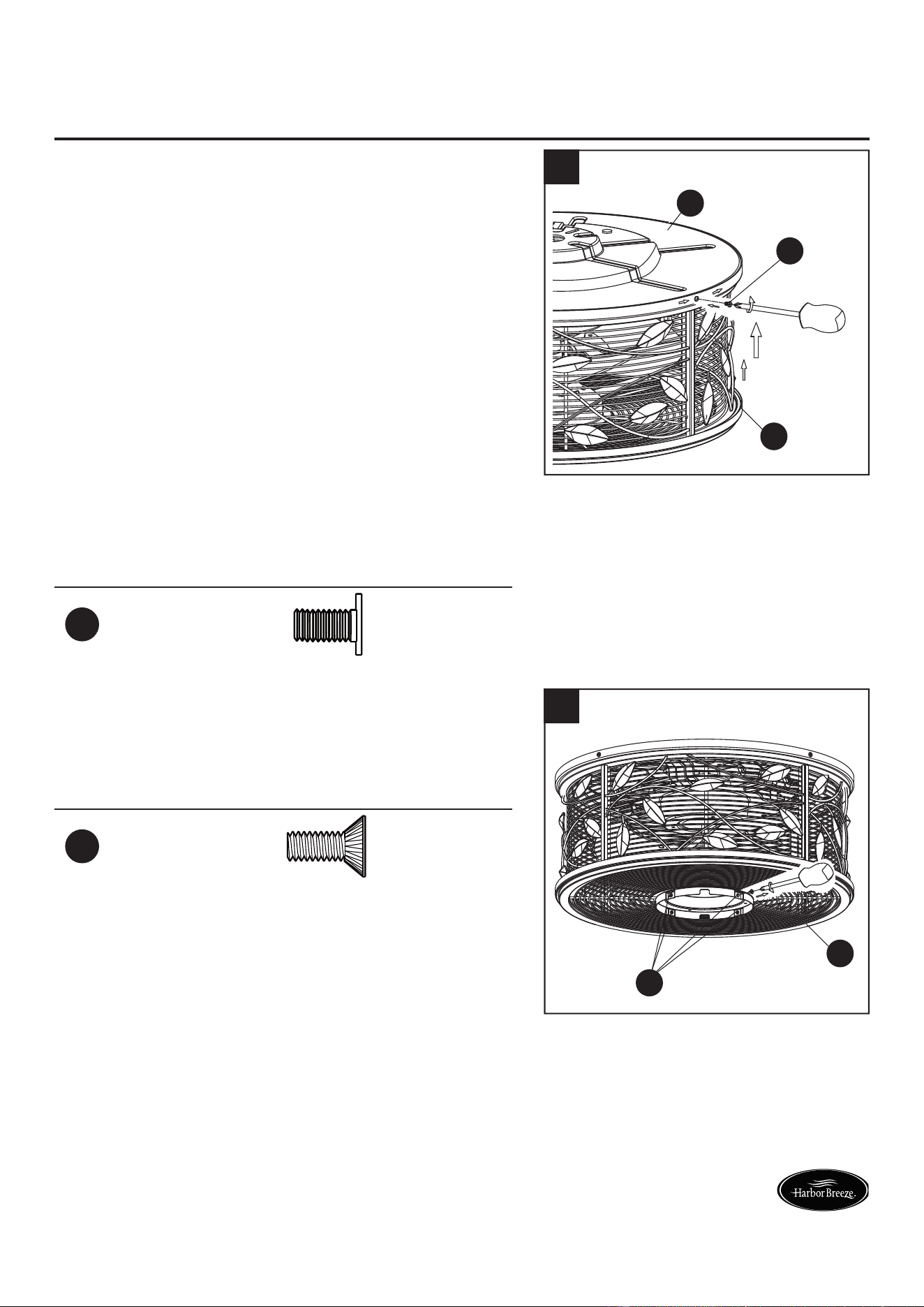
2. Remove the four preassembled switch housing
screws (CC) from the adapter switch housing of the
motor assembly (A). Retain the screws for later.
Hardware Used
CC
Switch Housing
Screw
x 4
CC
A
2
11
Lowes.com/harborbreeze
FINAL ASSEMBLY INSTRUCTIONS
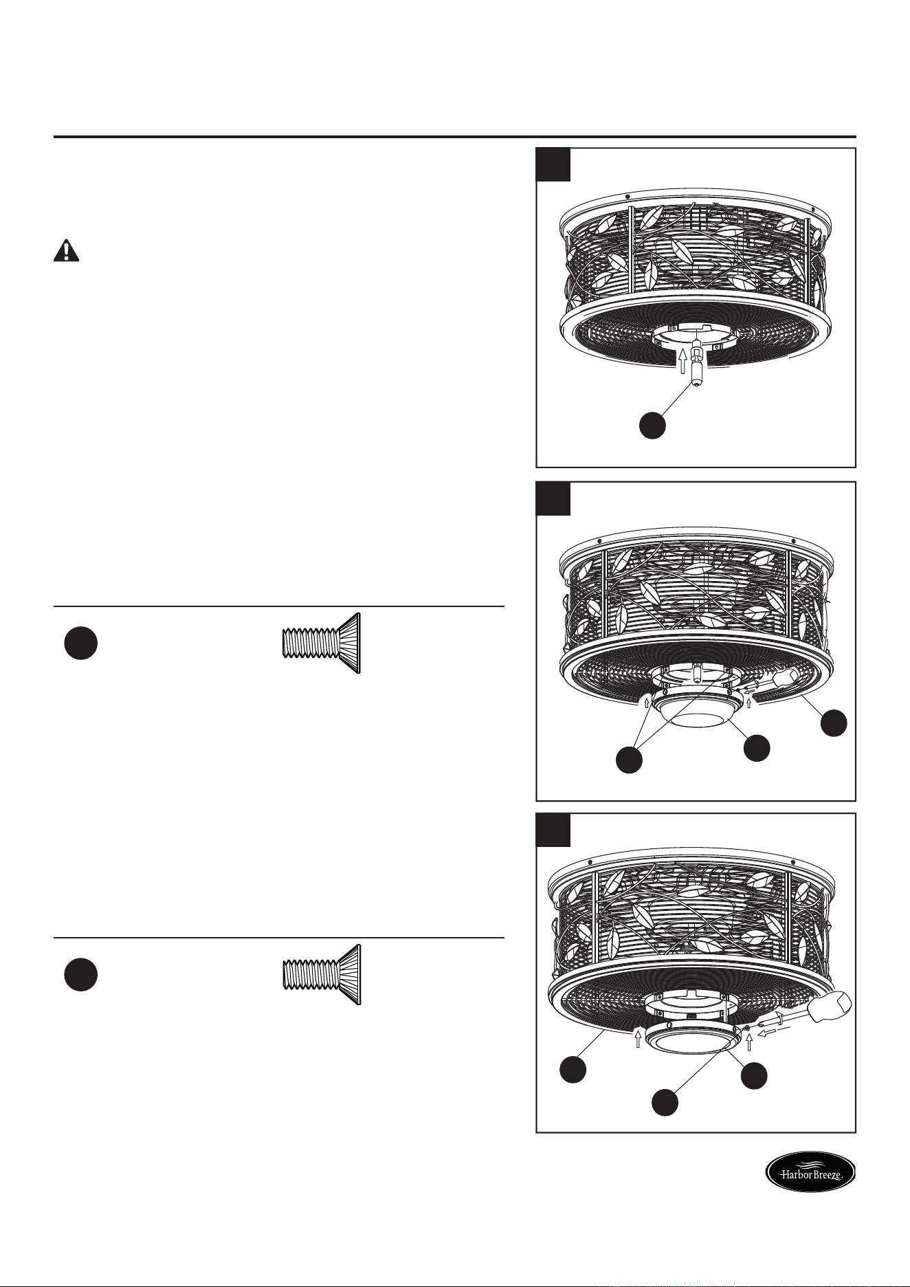
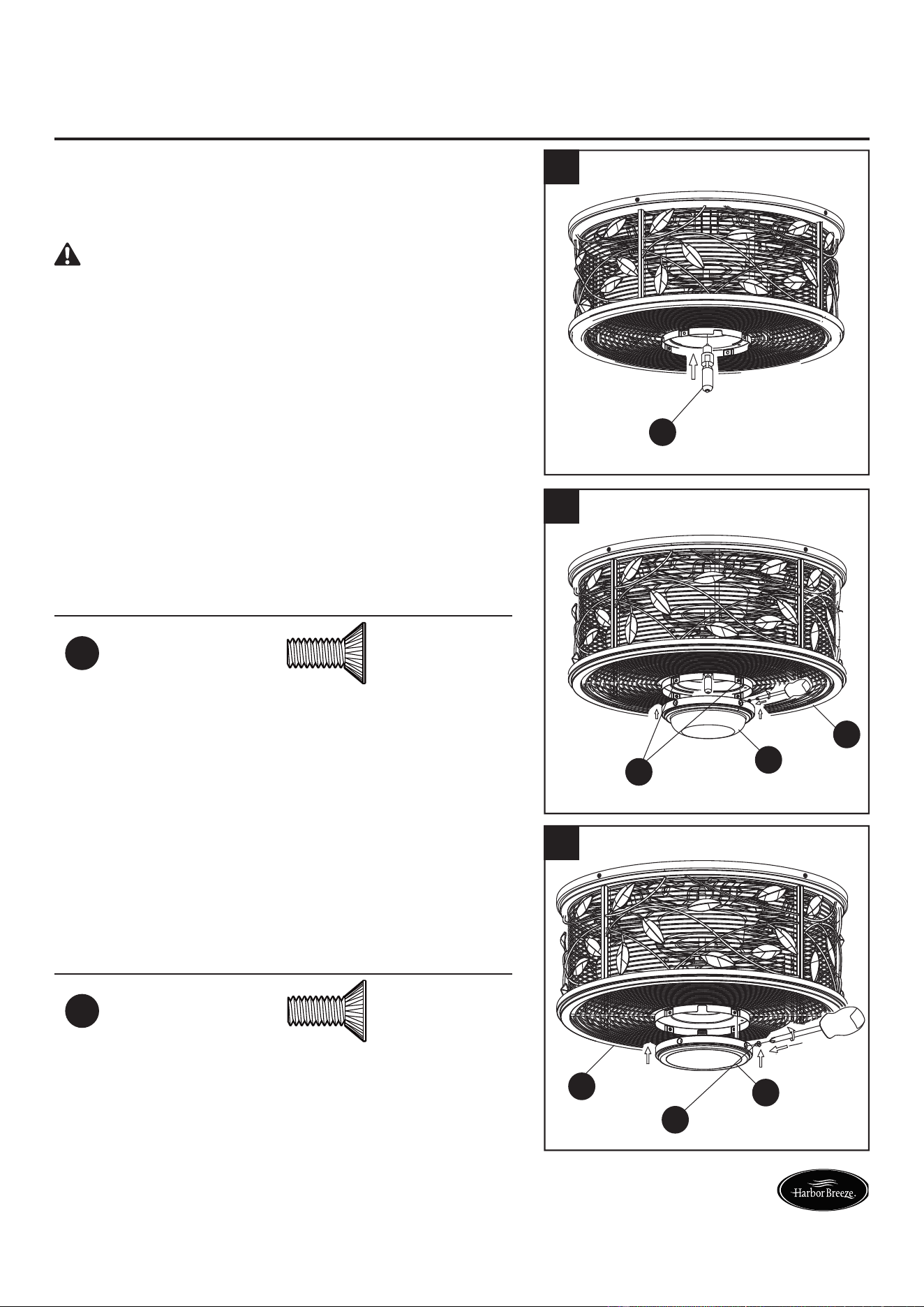
3. If you wish to use the light kit portion of the motor
assembly (A), install the bulb (D) and proceed to step
4. If you do not wish to use the light kit, skip to step 5
directly.
CAUTION: The bulb is pressurized and may shatter.
DO NOT TOUCH THE BULB WITH BARE HAND.
Fingerprints may result in shorter bulb life. Remove
fi ngerprints with alcohol prior to use. To reduce the risk of
fi re, use 75-watt max. type T4-minican JD E11 tungsten
halogen bulb. Turn off the wall switch and allow the bulb
to cool for 10 minutes before relamping.
D
3
4. Position the glass (B) onto the motor assembly (A)
and secure with the previously removed switch
housing screws (CC). Do not overtighten.
Assembly is now complete.
Hardware Used
CC
Switch Housing
Screw
x 4
A
B
CC
4
5. To use the fan without the light kit, position the steel
cap (C) onto the motor assembly (A) and secure with
the previously removed switch housing screws (CC).
Assembly is now complete.
Hardware Used
CC
Switch Housing
Screw
x 4
A
C
CC
5
12
Lowes.com/harborbreeze
OPERATING INSTRUCTIONS
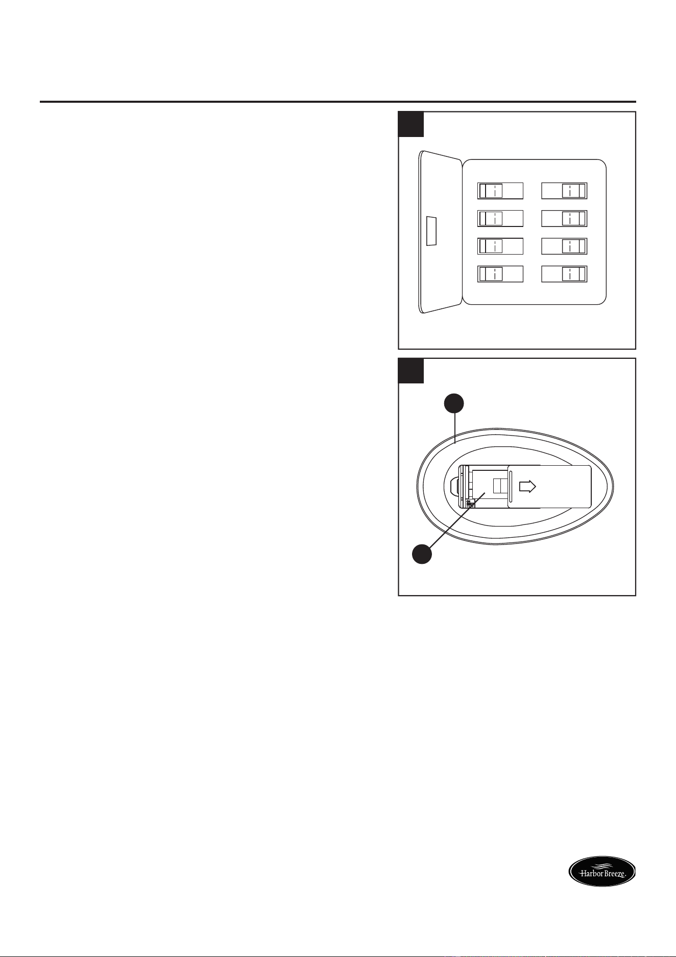
1. Restore electrical power to the outlet box by turning
the electricity on at the main fuse box.
ON
ON
ON
ON
ON
ON
ON
ON
1
2. Install the 12-volt battery (H) into the remote (E).
Press any key on the remote (E) to make sure the
blue light is on.
E
H
2
13
Lowes.com/harborbreeze
OPERATING INSTRUCTIONS (CONTINUED)
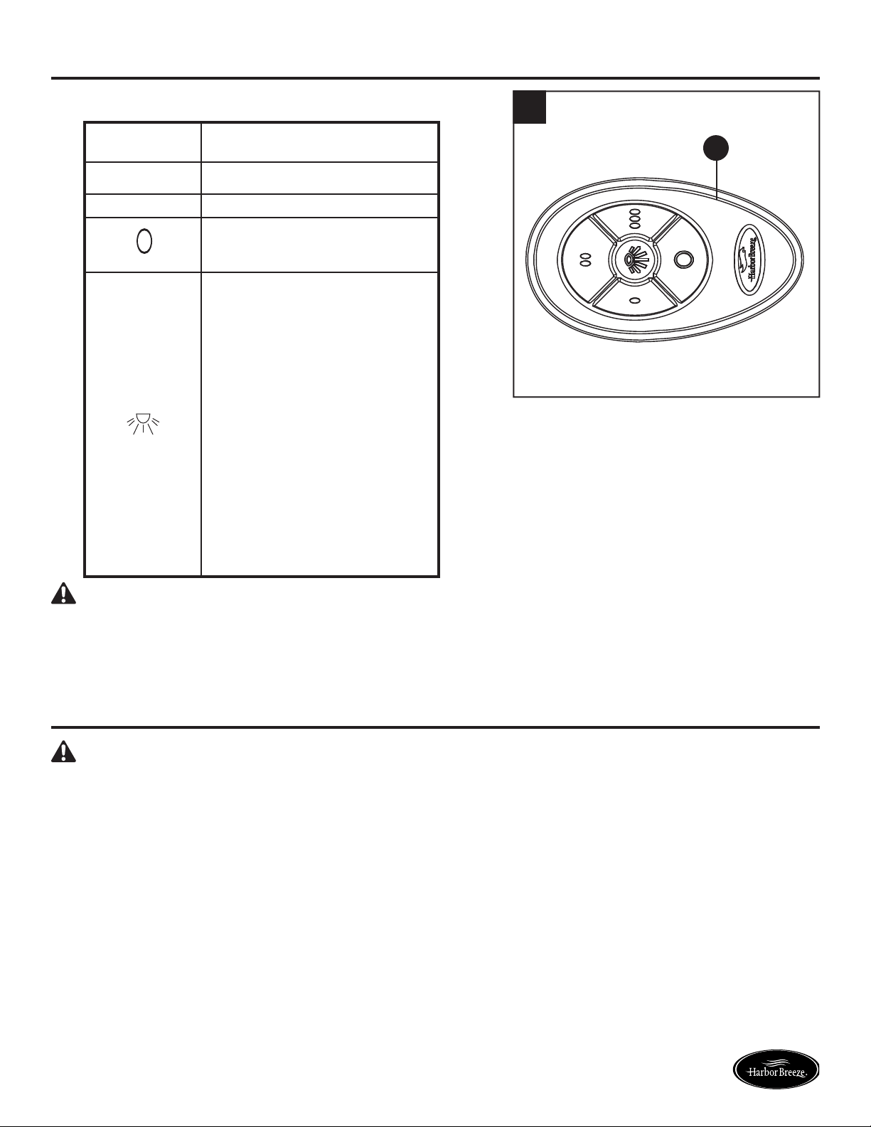
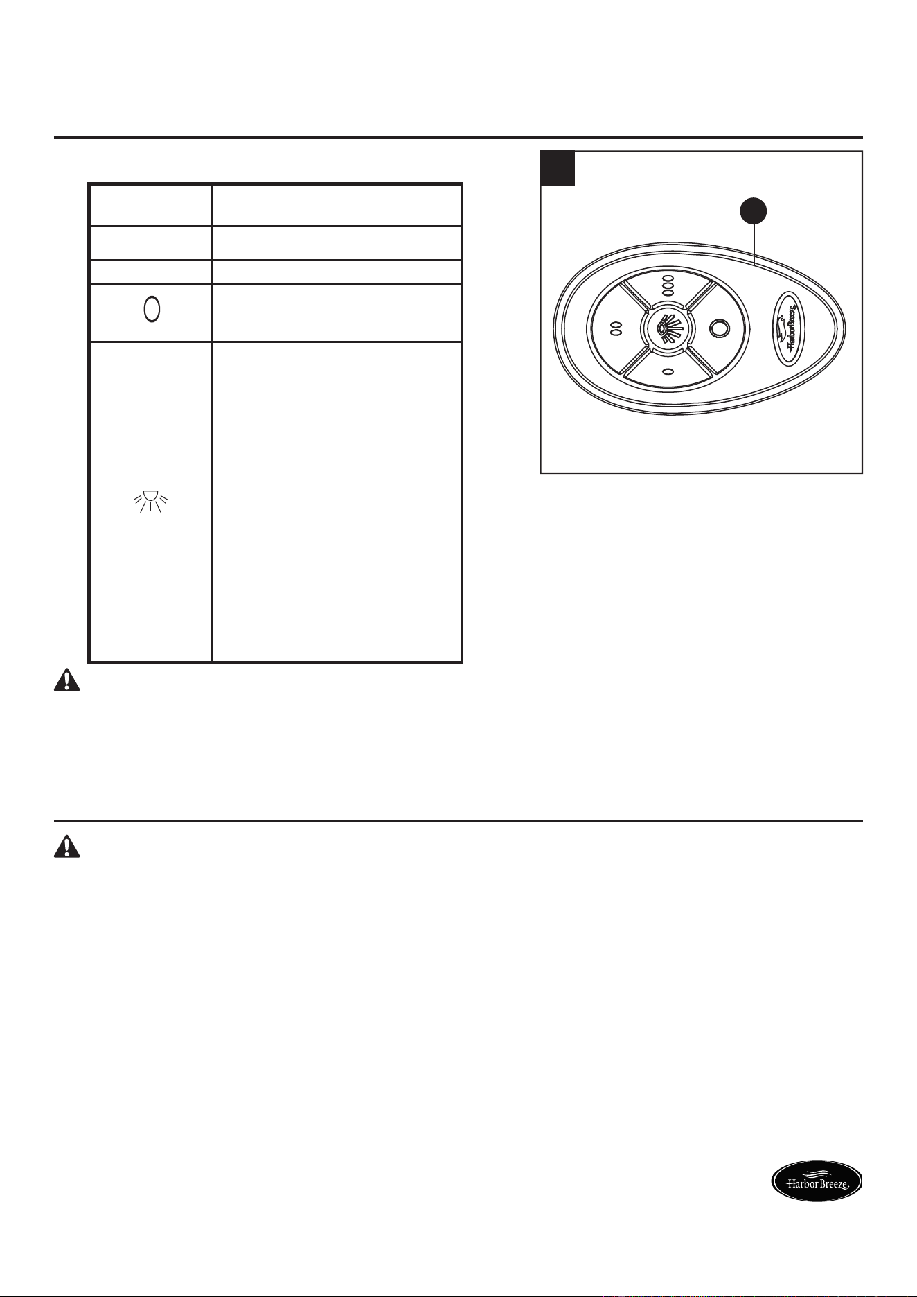
3. Control the fan and light:
0 Low Speed
00 Medium Speed
000 High Speed
Turn the fan off.
Press this button quickly
to turn the lights on or off.
To dim the lights, press
and hold this button.
Release the button when
the light is at the desired
level.
The receiver stores the
light setting when the light
is turned off. When the
light is turned on again,
it starts with the most
recent setting.
CAUTION: If you are not expecting to use the remote
for a long period of time, remove the battery to prevent
damage to the remote. Be sure to store the remote away
from excess heat or humidity.
E
3
CARE AND MAINTENANCE
WARNING: Do not use water when cleaning the ceiling fan. It could damage the motor or the
fi nish and create the possibility of electrical shock.
• When cleaning, use only a soft brush or lint-free cloth to avoid scratching the fi nish.
• Abrasive cleaning agents are not required and should be avoided to prevent damage to fi nish.
• Bulb Replacement: Use a 75-watt max. type T4-minican JD E11 tungsten halogen bulb.
• Re-lamp with the appropriate wattage bulb. Do not exceed the wattage indicated on the bulb
socket.
• Periodically check that the fan motor unit screws, blade screws, support
housing and light kit screws
are tight and secure.
• Avoid using water, cleansers, or harsh rags, which can warp and ruin the fi nish.
• Battery Replacement: Use one 23AE 12-volt alkaline battery.
14
Lowes.com/harborbreeze
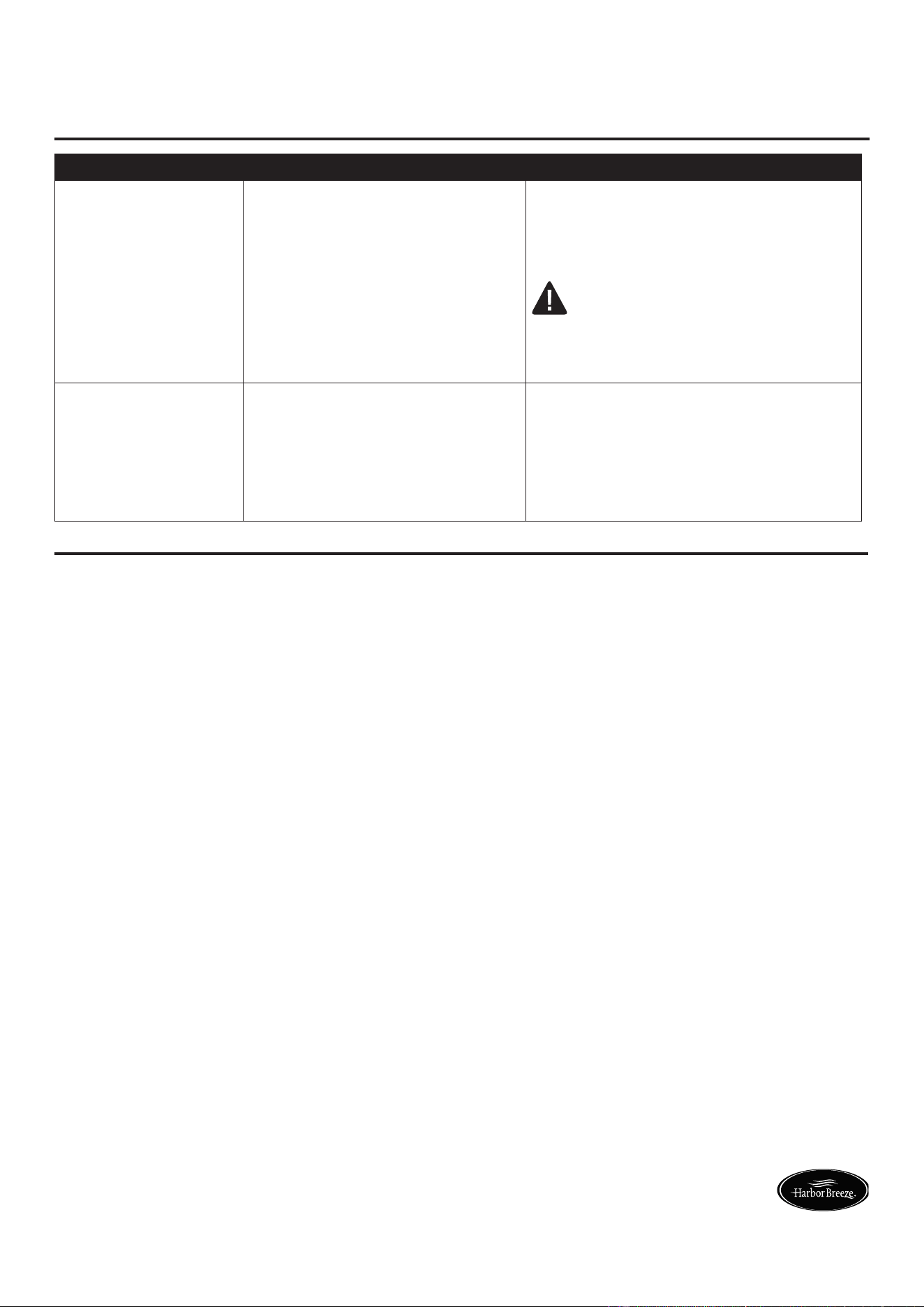
TROUBLESHOOTING
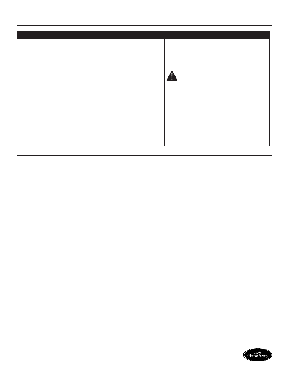
PROBLEM POSSIBLE CAUSE CORRECTIVE ACTION
The fan will not start. 1. The fuse or circuit breaker is
blown.
2. There are loose power line
connections to the fan.
3. The battery in the remote no
longer works.
1. Check the main and branch circuit
fuses or circuit breakers.
2. Check the line wire connections to
the fan.
WARNING: Ensure the main
power is turned off!
3. Replace with a new battery.
The fan sounds noisy. 1. There are loose screws in the
motor housing.
2. The wire connectors inside the
housing are rattling.
1. Check to make sure all screws in
the motor housing are snug (do not
overtighten).
2. Check to make sure the wire
connectors are not rattling against
each other or against the interior wall
of the motor assembly.
WARRANTY
The manufacturer warrants this fan to be free from defects in workmanship and material present at
time of shipment from the factory. The warranty terms from the date of purchase. The motor has a
lifetime warranty and a 2 year warranty for all remaining components. This warranty applies only to
the original purchaser. The manufacturer agrees to correct such defect at no charge or, at its option,
replace the ceiling fan with a comparable or superior model.
To obtain warranty service, present a copy of your sales receipt as proof of purchase. All cost of
removal and reinstallation are the expressed responsibility of the purchaser. Any damage to the
ceiling fan by accident, misuse or improper installation, or by affi xing accessories not produced by
this warranty, are at the purchaser’s own responsibility. The manufacturer assumes no responsibility
whatsoever for fan installation during the lifetime limited warranty. Any service performed by an
unauthorized person will render the warranty invalid.
Due to varying climate conditions, this warranty does not cover changes in brass fi nish, rusting,
pitting, tarnishing, corroding or peeling. Brass fi nish fans maintain their beauty when protected from
varying weather conditions. Any glass provided with this fan is not covered by the warranty.
Any replacement of defective parts for the ceiling fan must be reported within the fi rst year from the
date of purchase. For the balance of the warranty, call our customer service department at 1-800-643-
0067 for return authorization and shipping instructions so that we may repair or replace the ceiling
fan. Any fan or parts returned improperly packaged is the sole responsibility of the purchaser. There
is no further expressed warranty. The manufacturer disclaims any and all implied warranties. The
duration of any implied warranty which can not be disclaimed is limited to the lifetime limited period as
specifi ed in our warranty. The manufacturer shall not be liable for incidental, consequential or special
damages arising at or in connection with product use or performance except as may otherwise be
accorded by law. This warranty gives you specifi c legal rights and you also have other rights which
vary from state to state. This warranty supersedes all prior warranties.
Note: A small amount of “wobble” is normal and should not be considered a defect.

15
Lowes.com/harborbreeze
Printed in China
Harbor Breeze
®
is a registered trademark
of LF, LLC. All Rights Reserved.
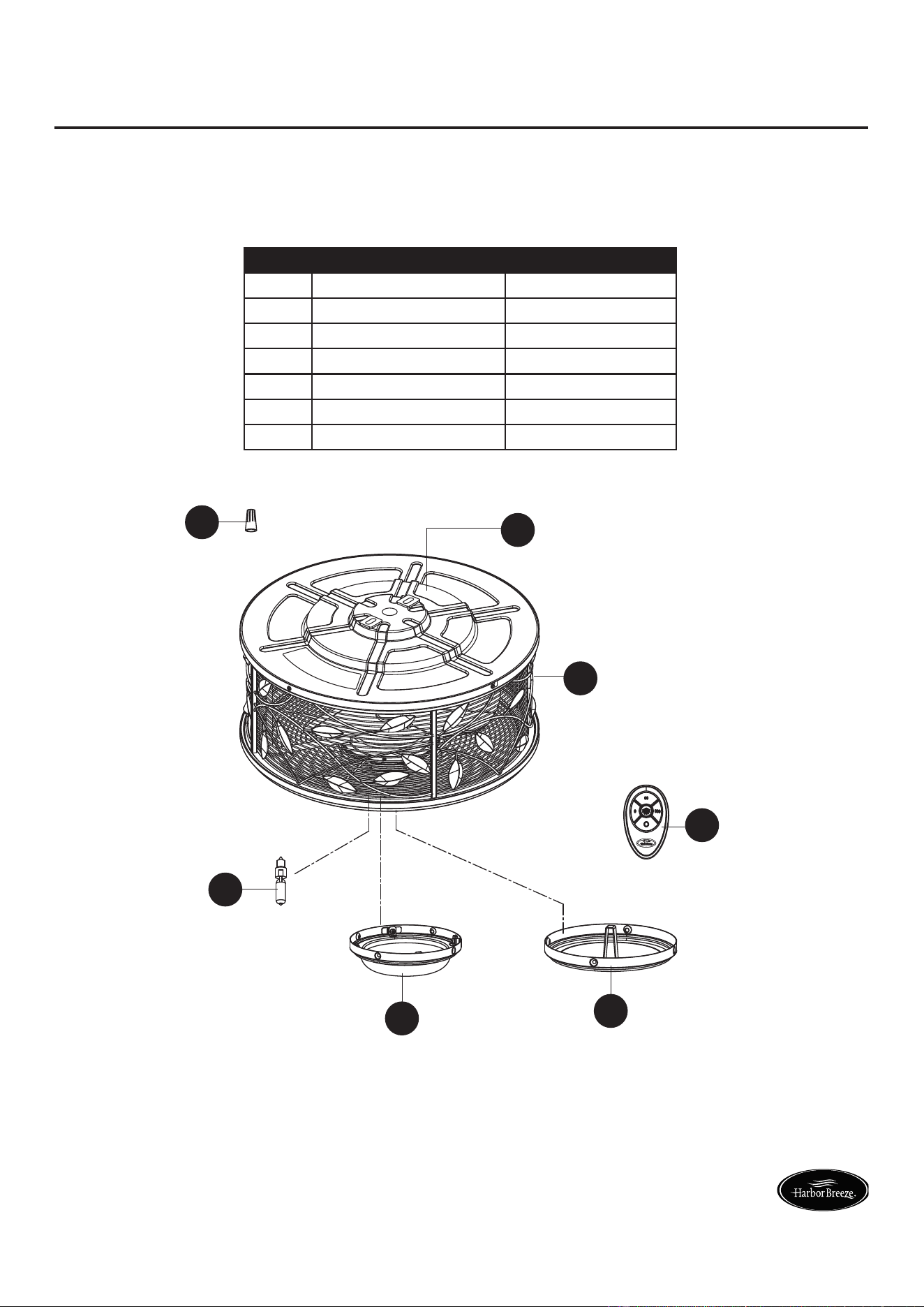
REPLACEMENT PARTS
For replacement parts, call our customer service department at 1-800-643-0067, 8 a.m. - 6 p.m., EST,
Monday - Thursday and 8 a.m. - 5 p.m., EST, Friday.
PART DESCRIPTION PART #
A Motor Assembly AMA8271LAZ
B Glass AP827115LAZ
C Steel Cap P827116LAZ
D Bulb PPE11B75
E Remote TR350
F Receiver Unit RECAN67
AA Wire Connector HDWWNUTS4
B
E
A
F
D
C
AA
¿Preguntas, problemas, piezas faltantes? Antes de volver a la tienda, llame a nuestro
Departamento de Servicio al Cliente al 1-800-643-0067, de lunes a jueves de
8 a.m. a 6 p.m., y los viernes de 8 a.m. a 5 p.m., hora estándar del Este.
16
ADJUNTE SU RECIBO AQUÍ
Número de serie ____________ Fecha de compra ____________
Lowes.com/harborbreeze
Harbor Breeze
®
es una marca registrada
de LF, LLC. Todos los derechos reservados.
ARTÍCULO #0449504
VENTILADOR DE TECHO
DE LA SERIE HIVE
MODELO #LP8271LAZ

17
Lowes.com/harborbreeze
ÍNDICE
Contenido del paquete . . . . . . . . . . . . . . . . . . . . . . . . . . . . . . . . . . . . . . . . . . . . . . . . . . . . . . . 18
Aditamentos . . . . . . . . . . . . . . . . . . . . . . . . . . . . . . . . . . . . . . . . . . . . . . . . . . . . . . . . . . . . . . . . . . 19
Información de seguridad
. . . . . . . . . . . . . . . . . . . . . . . . . . . . . . . . . . . . . . . . . . . . . . . . . . . . . . . . . .
19
Preparación . . . . . . . . . . . . . . . . . . . . . . . . . . . . . . . . . . . . . . . . . . . . . . . . . . . . . . . . . . . . . . . . . . 20
Instrucciones de ensamblaje . . . . . . . . . . . . . . . . . . . . . . . . . . . . . . . . . . . . . . . . . . . . . . . . . . . . . 21
Instrucciones del control remoto . . . . . . . . . . . . . . . . . . . . . . . . . . . . . . . . . . . . . . . . . . . . . . . . . . 23
Instrucciones de cableado . . . . . . . . . . . . . . . . . . . . . . . . . . . . . . . . . . . . . . . . . . . . . . . . . . . . . . . 24
Instrucciones de ensamblaje fi nales . . . . . . . . . . . . . . . . . . . . . . . . . . . . . . . . . . . . . . . . . . . . . . . 25
Instrucciones de funcionamiento . . . . . . . . . . . . . . . . . . . . . . . . . . . . . . . . . . . . . . . . . . . . . . . . . . 27
Cuidado y mantenimiento . . . . . . . . . . . . . . . . . . . . . . . . . . . . . . . . . . . . . . . . . . . . . . . . . . . . . . . 28
Solución de problemas
. . . . . . . . . . . . . . . . . . . . . . . . . . . . . . . . . . . . . . . . . . . . . . . . . . . . . . . . . . . . .
29
Garantía . . . . . . . . . . . . . . . . . . . . . . . . . . . . . . . . . . . . . . . . . . . . . . . . . . . . . . . . . . . . . . . . . . 29
Lista de piezas de repuesto . . . . . . . . . . . . . . . . . . . . . . . . . . . . . . . . . . . . . . . . . . . . . . . . . . . . . . . . . . 30
18
Lowes.com/harborbreeze
CONTENIDO DEL PAQUETE
B
G
C
D
E
A
F
H
PIEZA DESCRIPCIÓN CANT.
A Ensamble del motor 1
B Vidrio 1
C Tapa de acero 1
D Bombilla 1
E Control remoto 1
F
Receptor (Preensamblado en el ensamble del motor (A))
1
G
Abrazadera para techo (preensamblada en el ensamble
del motor (A))
1
H Batería 1
19
Lowes.com/harborbreeze
ADITAMENTOS (no se muestran en tamaño real)
AA
BB
CC
Conector
de cables
Cant. 4
Tornillo de la
abrazadera para techo
(preensamblado en el
ensamble del motor (A))
Cant. 4
Tornillo de la carcasa
del interruptor
(preensamblado en el
ensamble del motor (A))
Cant. 4
INFORMACIÓN DE SEGURIDAD
Lea y comprenda completamente este manual antes de intentar ensamblar, usar o instalar el producto.
LEA Y GUARDE ESTAS INSTRUCCIONES.
ADVERTENCIA: PARA REDUCIR EL RIESGO DE INCENDIOS, DESCARGAS ELÉCTRICAS
O LESIONES PERSONALES, SIGA LAS SIGUIENTES INSTRUCCIONES:
• Antes de comenzar la instalación del ventilador, desconecte la alimentación eléctrica retirando
los fusibles o colocando el interruptor de circuito en la posición de apagado.
• Asegúrese de que todas las conexiones eléctricas cumplan con los códigos u ordenanzas locales
o el Código Eléctrico Nacional. Si no está familiarizado con la instalación del cableado eléctrico,
contrate a un electricista califi cado o consulte un manual de cableado para hacerlo usted mismo.
• Si va a montar el ventilador en una caja de salida del techo, use una caja de salida octogonal de
METAL. Asegure la caja directamente a la estructura del edifi cio. La caja de salida y su soporte
deben ser capaces de sostener el peso del ventilador en movimiento (al menos 15,88 kg).
NO use una caja de salida de plástico.
• Una vez instalado el ventilador, asegúrese de que todas las conexiones sean seguras a fi n de
evitar que se caiga.
• En lo que respecta a las conexiones de suministro, si el conductor del ventilador está identifi cado
como conductor con puesta a tierra, se le debe conectar a un suministro de electricidad con
conductor de puesta a tierra. Si el conductor del ventilador está identifi cado como conductor que
no es de puesta a tierra, se le debe conectar a un suministro de electricidad con conductor sin
puesta a tierra. Si el conductor del ventilador está identifi cado para equipos de puesta a tierra,
se le debe conectar al conductor de equipos de puesta a tierra.
• Este dispositivo cumple con la sección 15 de las reglas de la FCC. El funcionamiento está sujeto
a las siguientes dos condiciones: (1) Este dispositivo no debe causar interferencia perjudicial,
y (2) deberá aceptar cualquier interferencia recibida, incluida la interferencia que pudiese causar
la operación no deseada.
• Este equipo ha sido probado y se ha verifi cado que cumple con los límites para un dispositivo digital
clase B, conforme a la sección 15 de las regulaciones de la FCC. Estos límites se han diseñado
para proporcionar una protección razonable contra la interferencia perjudicial en una instalación
residencial. Este equipo genera, usa y puede irradiar energía de radiofrecuencia y, si no se instala
y usa de acuerdo con las instrucciones, puede causar interferencia perjudicial a la recepción de
radio o televisión, lo que se puede determinar al apagar y encender el equipo. Se recomienda al
usuario que intente corregir la interferencia con una o más de las siguientes medidas:
- Reoriente o reubique la antena de recepción.
- Aumente la separación entre el equipo y el receptor.
- Conecte el equipo a un tomacorriente de un circuito distinto al que usa el receptor.
- Solicite ayuda al concesionario o a un técnico con experiencia en radio/TV.
20
Lowes.com/harborbreeze
INFORMACIÓN DE SEGURIDAD
ADVERTENCIA: No instale ni use el ventilador si falta alguna pieza o si estas están dañadas.
ADVERTENCIA: Para reducir el riesgo de incendios, descargas eléctricas o lesiones personales,
los conectores de cables proporcionados con este ventilador están diseñados para soportar solo
un cable de la casa de calibre 12 y dos cables conductores del ventilador. Si el cable de su casa
es de un calibre superior a 12 o hay más de un cable para conectar los dos cables conductores del
ventilador, pregúntele a un electricista cuál es el tamaño adecuado de los conectores de cables que
debe utilizar. Antes de cortar, taladrar o martillar, verifi que la ubicación de los conductores. Póngase
en contacto con su electricista, plomero o con un técnico califi cado si es necesario.
ADVERTENCIA: Para reducir el riesgo de incendio, descargas eléctricas o lesiones personales,
monte el ventilador en una caja de salida marcada como “Apta para sostener ventiladores de
15,88 kg o menos
” y use los tornillos de montaje provistos con la caja de salida y/o cuélguelo
directamente de la estructura del edifi cio. La mayoría de las cajas de salida que se usan
comúnmente para sostener ensambles de iluminación no son aptas para sostener un ventilador
y puede ser necesario reemplazarlas. Si tiene dudas, consulte a un electricista califi cado.
ADVERTENCIA: Para reducir el riesgo de incendios o descargas eléctricas, no use este
ventilador con dispositivos de control de velocidad de estado sólido.
ADVERTENCIA: Este ventilador es apto solo para lugares secos.
ADVERTENCIA: Antes de reparar o limpiar la unidad, corte la energía en el panel de servicio
y bloquee los medios de desconexión del servicio, a fi n de impedir la activación accidental de la
energía. Cuando no sea posible bloquear los medios de desconexión del servicio, fi je un dispositivo
de advertencia que se destaque al panel de servicio, como por ejemplo una etiqueta.
PRECAUCIÓN: Lea todas las instrucciones y la información de seguridad antes de instalar
el nuevo ventilador. Revise los diagramas de ensamblaje adjuntos.
PREPARACIÓN
Antes de comenzar a ensamblar este producto, asegúrese de tener todas las piezas. Compare todas
las piezas con la lista del contenido del paquete y la lista de aditamentos. No intente ensamblar
el producto si falta alguna pieza o si estas están dañadas.
Después de abrir la parte superior de la caja, retire el paquete de aditamentos de montaje de los
accesorios de espuma. Luego, retire el motor del ensamble y colóquelo en una superfi cie suave,
como una alfombra, para evitar dañar el acabado.
Tiempo estimado de ensamblaje: 60 minutos.
Herramientas necesarias para el ensamblaje (no se incluyen): Cinta aislante, destornillador Phillips,
destornillador de cabeza plana de 1/4”, pinzas, gafas de seguridad, escalera de tijera y pinzas
pelacables.
Herramientas útiles (no se incluyen): Luz de prueba de CA, cinta métrica, manual de cableado
y pinzas cortacables.
21
Lowes.com/harborbreeze
INSTRUCCIONES DE ENSAMBLAJE INICIALES
1. Desconecte la electricidad en la caja de fusibles
principal antes de ensamblar.
PELIGRO: Si no interrumpe el suministro de
electricidad antes de la instalación, pueden producirse
lesiones graves o la muerte.
ON
ON
ON
ON
ON
ON
ON
ON
1
2. Separe la abrazadera para techo (G) del ensamble del
motor (A), afl ojando los dos tornillos de la abrazadera
para techo (BB) en los orifi cios ranurados y luego
retirando los dos tornillos de las abrazaderas para
techo (BB) restantes en el ensamble del motor (A).
Guarde los tornillos para más adelante.
Aditamentos utilizados
BB
Tornillo de la
abrazadera
para techo
x 4
A
G
BB
2
3. Si aún no termina, asegure la caja de salida octagonal
de metal (no se incluye) directamente a la estructura
del edifi cio.
Nota: Se omitieron los cables conductores para mayor
claridad.
3
22
Lowes.com/harborbreeze
INSTRUCCIONES DE ENSAMBLAJE INICIALES
4. Fije bien la abrazadera para techo (G) a la caja de
salida con los tornillos y las arandelas provistas con
la caja de salida.
G
4
5. Enganche el cable de soporte para techo
preensamblado desde el ensamble del motor (A)
sobre el gancho en la abrazadera para techo (G).
G
A
5
23
Lowes.com/harborbreeze
INSTRUCCIONES DEL CONTROL REMOTO
1. Para confi gurar el código del transmisor en el
control remoto (E), retire la cubierta de la batería.
Con un pequeño destornillador o un lápiz de punta
redonda (no se incluye), deslice los interruptores de
código hacia arriba o hacia abajo a la confi guración
que desee.
Nota: La confi guración de fábrica es la de más arriba;
no utilice esta posición.
Vuelva a colocar la cubierta de la batería en el
control remoto (E).
E
1
2. Deslice los interruptores de código en el receptor (F)
a las mismas posiciones que en el control remoto (E).
Cuando se colocan dos o más ventiladores cerca,
confi gure el receptor/control remoto para cada
ventilador en un código distinto, de manera que
el funcionamiento de este ventilador no afecte el
funcionamiento de los demás.
Nota: Antes de cambiar las confi guraciones de código,
asegúrese de que la batería en el control remoto (E)
esté desconectada.
F
2
24
Lowes.com/harborbreeze
INSTRUCCIONES DE CABLEADO
Nota: Si no está seguro de si la caja de salida tiene puesta a tierra, solicite ayuda a un electricista
certifi cado, ya que debe tener puesta a tierra para un funcionamiento seguro.
1. Conecte el conductor verde con puesta a tierra
de la bandeja de conductores y el conductor
verde con puesta a tierra de la abrazadera para
techo (G) al conductor de suministro con puesta
a tierra (posiblemente un conductor desnudo o un
conductor con aislamiento verde). Conecte bien
los conductores con un conector de cables (AA).
Conecte el conductor blanco receptor del motor
del ventilador al conductor blanco (neutro) con
un conector de cables (AA). Conecte el conductor
negro receptor del motor del ventilador al conductor
negro con un conector de cables (AA).
Aditamentos utilizados
AA
Conector de
cables
x 3
AA
AA
1
2. Una vez realizadas las conexiones, gire los
conductores hacia arriba y colóquelos con
cuidado dentro de la abrazadera para techo (G),
con los conductores blancos y verdes hacia un
lado y los conductores negros hacia el otro.
ADVERTENCIA: Verifi que que todas las conexiones
estén ajustadas, incluyendo la puesta a tierra, y que no
haya conductores desnudos visibles en los conectores
de cables, excepto el conductor con puesta a tierra.
G
2
25
Lowes.com/harborbreeze
INSTRUCCIONES DE ENSAMBLAJE FINALES
1. Sostenga el ensamble del motor (A) y libérelo
del gancho en la abrazadera para techo (G).
El ensamble del motor (A) tiene dos ranuras y dos
orifi cios de acoplamiento. Coloque ambas ranuras
del ensamble del motor (A) directamente debajo
y alineadas con los dos tornillos de la abrazadera
para techo (BB) en la abrazadera para techo (G).
Levante el ensamble del motor (A), permitiendo que
los dos tornillos de la abrazadera para techo (BB)
se deslicen dentro de las ranuras de acoplamiento.
Gire el ensamble del motor (A) hasta que ambos
tornillos de la abrazadera para techo (BB) caigan
en los huecos de las ranuras en el ensamble del
motor (A). Apriete bien los tornillos de la abrazadera
para techo (BB). Luego, instale los tornillos de la
abrazadera para techo (BB) que retiró en los orifi cios
de acoplamiento de la abrazadera para techo (G)
para fi jar el ensamble del motor (A) a la abrazadera
para techo (G).
Aditamentos utilizados
BB
Tornillo de la
abrazadera
para techo
x 4
G
BB
A
1
2. Retire la cubierta de los cuatro tornillos de la carcasa
del interruptor (CC) de la carcasa del interruptor del
adaptador del ensamble del motor (A). Guarde los
tornillos para más adelante.
Aditamentos utilizados
CC
Tornillo de la
carcasa del
interruptor
x 4
CC
A
2
26
Lowes.com/harborbreeze
INSTRUCCIONES DE ENSAMBLAJE FINALES
3. Si desea usar la sección del kit de iluminación del
ensamble del motor (A), instale la bombilla (D)
y continúe con el paso 4. Si no desea utilizar el
kit de iluminación, pase directamente al paso 5.
PRECAUCIÓN: La bombilla está presurizada y
puede quebrarse. NO TOQUE LA BOMBILLA CON
LAS MANOS DESCUBIERTAS. Las huellas dactilares
en la bombilla pueden reducir la vida útil de la misma.
Elimine las huellas dactilares con alcohol antes de usar
la bombilla. Para disminuir el riesgo de incendios, utilice
una bombilla minican de tungsteno halógena tipo T4 JD
E11 de 75 vatios como máximo. Apague el interruptor de
pared y deje enfriar la bombilla durante 10 minutos antes
de cambiarla.
D
3
4. Coloque el vidrio (B) en el ensamble del motor (A)
y fíjelo con los tornillos de la carcasa del interruptor
(CC) retirados anteriormente. No apriete demasiado.
El ensamblaje está completo.
Aditamentos utilizados
CC
Tornillo de la
carcasa del
interruptor
x 4
A
B
CC
4
5. Para usar el ventilador sin el kit de iluminación,
coloque la tapa de acero (C) en el ensamble del
motor (A) y fíjelo con los tornillos de la carcasa
del interruptor (CC) retirados anteriormente.
El ensamblaje está completo.
Aditamentos utilizados
CC
Tornillo de la
carcasa del
interruptor
x 4
A
C
CC
5

27
Lowes.com/harborbreeze
INSTRUCCIONES DE FUNCIONAMIENTO
1. Restablezca la alimentación eléctrica en la caja de
salida volviendo a conectar la electricidad de la caja
de fusibles principal.
ON
ON
ON
ON
ON
ON
ON
ON
1
2. Instale la batería de 12 voltios (H) en el control
remoto (E). Presione cualquier tecla en el control
remoto (E) para asegurarse de que la luz azul
se encienda.
E
H
2
28
Lowes.com/harborbreeze
INSTRUCCIONES DE FUNCIONAMIENTO (CONTINUACIÓN)
3. Controle el ventilador y la luz:
0 Velocidad baja
00 Velocidad media
000 Velocidad alta
Apague el ventilador.
Presione rápidamente este
botón para encender o apagar
las luces.
Mantenga presionado este
botón para regular la intensidad
de las luces.
Cuando la intensidad de la
luz alcance el nivel deseado,
suelte el botón.
El receptor registra la intensidad
de la luz al apagarla. Cuando
se vuelve a encender la luz, se
pone en funcionamiento con el
último ajuste establecido.
PRECAUCIÓN: Si el producto no se usará por un
período prolongado, retire la batería para evitar que
se dañe el control remoto. Asegúrese de almacenar el
control remoto alejado del calor y humedad extremos.
E
3
CUIDADO Y MANTENIMIENTO
ADVERTENCIA: No use agua para limpiar el ventilador de techo. Puede dañar el motor
o el acabado y crea la posibilidad de una descarga eléctrica.
• Use solo una brocha suave o un paño que no produzca pelusas para evitar rayar el acabado al
limpiarlo.
• Los agentes limpiadores abrasivos son innecesarios y deben evitarse para no dañar el acabado.
• Reemplazo de la bombilla: Use una bombilla minican de tungsteno halógena tipo T4 JD E11 de
75 vatios como máximo.
• Cambie la bombilla por una del vataje correcto. No exceda el vataje máximo indicado en el
portalámpara.
• Revise periódicamente que los tornillos del motor, los tornillos de las aspas, la carcasa
de soporte
y los tornillos del kit de iluminación del ventilador estén apretados y fi rmes.
• Evite usar agua, limpiadores o paños ásperos, ya que pueden combar y arruinar el acabado.
• Reemplazo de la batería: Use una batería alcalina 23AE de 12 voltios.
29
Lowes.com/harborbreeze
SOLUCIÓN DE PROBLEMAS
PROBLEMA CAUSA POSIBLE ACCIÓN CORRECTIVA
El ventilador
no arranca.
1. El fusible o el interruptor de
circuito están fundidos.
2. Alguna de las conexiones
eléctricas que van al ventilador
está suelta.
3. La batería del control remoto
ya no funciona.
1. Revise los fusibles del circuito de
derivación y del circuito principal o los
interruptores de circuito.
2. Revise las conexiones de los cables
que van hacia el ventilador.
ADVERTENCIA: Asegúrese de
que alimentación eléctrica esté cortada.
3. Reemplace con una batería nueva.
El ventilador emite
mucho ruido.
1. Hay tornillos sueltos en la
carcasa del motor.
2. Los conectores de cables
al interior de la carcasa
repiquetean.
1. Compruebe que todos los tornillos de
la carcasa del motor estén apretados
(no apriete demasiado).
2. Compruebe que los conectores de
cables no repiqueteen unos contra
otros o contra las paredes interiores
del ensamble del motor.
GARANTÍA
El fabricante garantiza que este ventilador no presenta defectos de fabricación ni en los materiales
presentes en el momento del transporte desde la fábrica. La garantía es efectiva desde la fecha de compra.
El motor tiene una garantía de por vida y una garantía de 2 años para todos los componentes restantes.
Esta garantía es válida solo para el comprador original. El fabricante acepta reparar dichos defectos sin
cargo o, según su criterio, reemplazar el ventilador de techo por un modelo comparable o superior.
Para obtener el servicio de garantía, presente una copia del recibo de venta como comprobante de la
compra. Todos los costos de extracción y reinstalación son de responsabilidad explícita del comprador.
Cualquier daño al ventilador de techo producido por accidente, uso indebido o instalación incorrecta,
o a causa de accesorios de fi jación que no están cubiertos por esta garantía, será responsabilidad
del comprador. El fabricante no asume ningún tipo de responsabilidad por la instalación del ventilador
durante la garantía limitada de por vida. Cualquier servicio realizado por una persona no autorizada
invalidará la garantía.
Debido a las cambiantes condiciones climáticas, esta garantía no cubre cambios en el acabado de latón,
óxido, picaduras, deslustre, corrosión o descascarado. Los ventiladores con acabado de latón mantienen
su belleza cuando se les protege de las cambiantes condiciones climáticas. La garantía no cubre los
elementos de vidrio incluidos con este ventilador.
Cualquier reemplazo de piezas defectuosas para el ventilador de techo debe informarse dentro del primer
año a partir de la fecha de compra. Para conocer el saldo de la garantía, llame a nuestro Departamento de
Servicio al Cliente al 1-800-643-0067 para obtener la autorización para la devolución y las instrucciones
de envío, de modo que podamos reparar o reemplazar el ventilador de techo. Un ventilador o piezas
devueltas con un embalaje incorrecto son de responsabilidad única del comprador. No existe otro tipo de
garantía explícita. El fabricante rechaza cualquiera y todas las garantías implícitas. La duración de cualquier
garantía implícita que no pueda rechazarse se limita al período limitado de por vida especifi cado en nuestra
garantía. El fabricante no será responsable por daños incidentales, resultantes o especiales que surjan en
relación con el uso o el funcionamiento del producto, excepto que la ley indique lo contrario. Esta garantía
le otorga derechos legales específi cos, y usted tiene también otros derechos que varían según el estado.
Esta garantía sustituye cualquier garantía previa.
Nota: Una pequeña cantidad de “tambaleo” es normal y no se debe considerar como un defecto.
30
Lowes.com/harborbreeze
Impreso en China
Harbor Breeze
®
es una marca registrada
de LF, LLC. Todos los derechos reservados.
PIEZAS DE REPUESTO
Para obtener piezas de repuesto, llame a nuestro Departamento de Servicio al Cliente al 1-800-643-0067,
de lunes a jueves de 8 a.m. a 6 p.m., y los viernes de 8:00 a.m. a 5 p.m., hora estándar del Este.
PIEZA DESCRIPCIÓN PIEZA #
A Ensamble del motor AMA8271LAZ
B Vidrio AP827115LAZ
C Tapa de acero P827116LAZ
D Bombilla PPE11B75
E Control remoto TR350
F Unidad receptora RECAN67
AA Conector de cables HDWWNUTS4
B
E
A
F
D
C
AA