Español p. 19
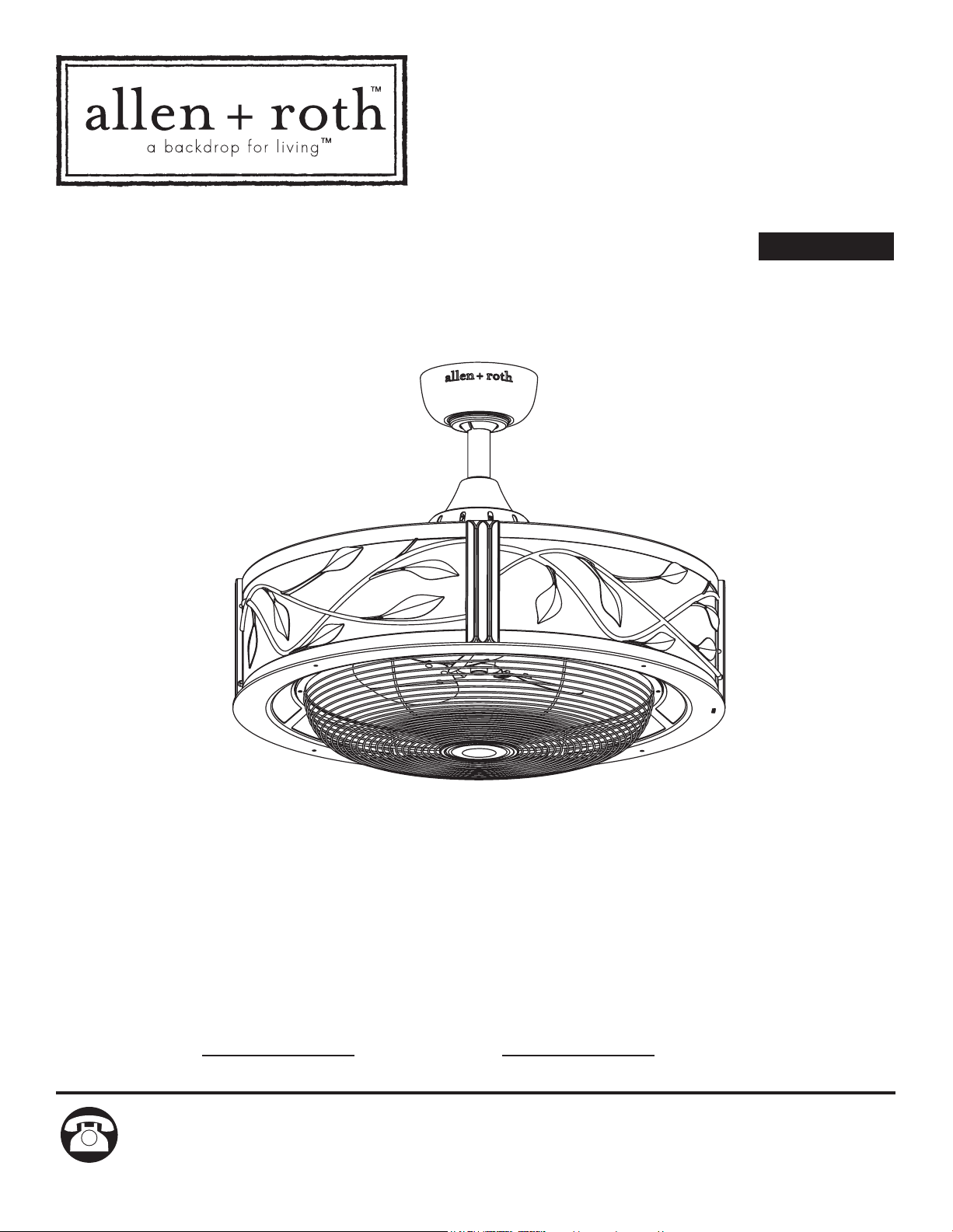
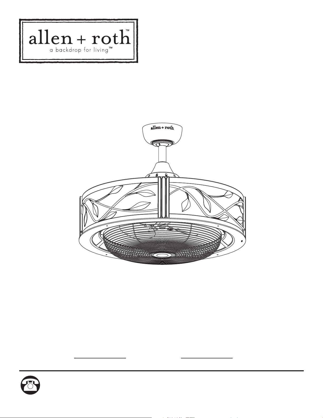
ITEM #0331091
MODEL #LP8074LAZ
EASTVIEW CEILING FAN
ATTACH YOUR RECEIPT HERE
Serial Number
Purchase Date
Questions, problems, missing parts? Before returning to your retailer, call our customer
service department at 1-888-567-2055, 8 a.m. - 5 p.m., EST, Monday - Friday.
PRODUCT SPECIFICATIONS
TABLE OF CONTENTS
Safety Information .........................................................................................................................
Package Contents .........................................................................................................................
Hardware Contents .......................................................................................................................
Preparation ...................................................................................................................................
Assembly Instructions ...................................................................................................................
Hanging Instructions .....................................................................................................................
Wiring Instructions ........................................................................................................................
Canopy Housing Installation .........................................................................................................
Light Bulb Installation ...................................................................................................................
Fan Operating Instructions ...........................................................................................................
Care and Maintenance .................................................................................................................
Troubleshooting
............................................................................................................................
Warranty
.......................................................................................................................................
Replacement Parts List
................................................................................................................
2
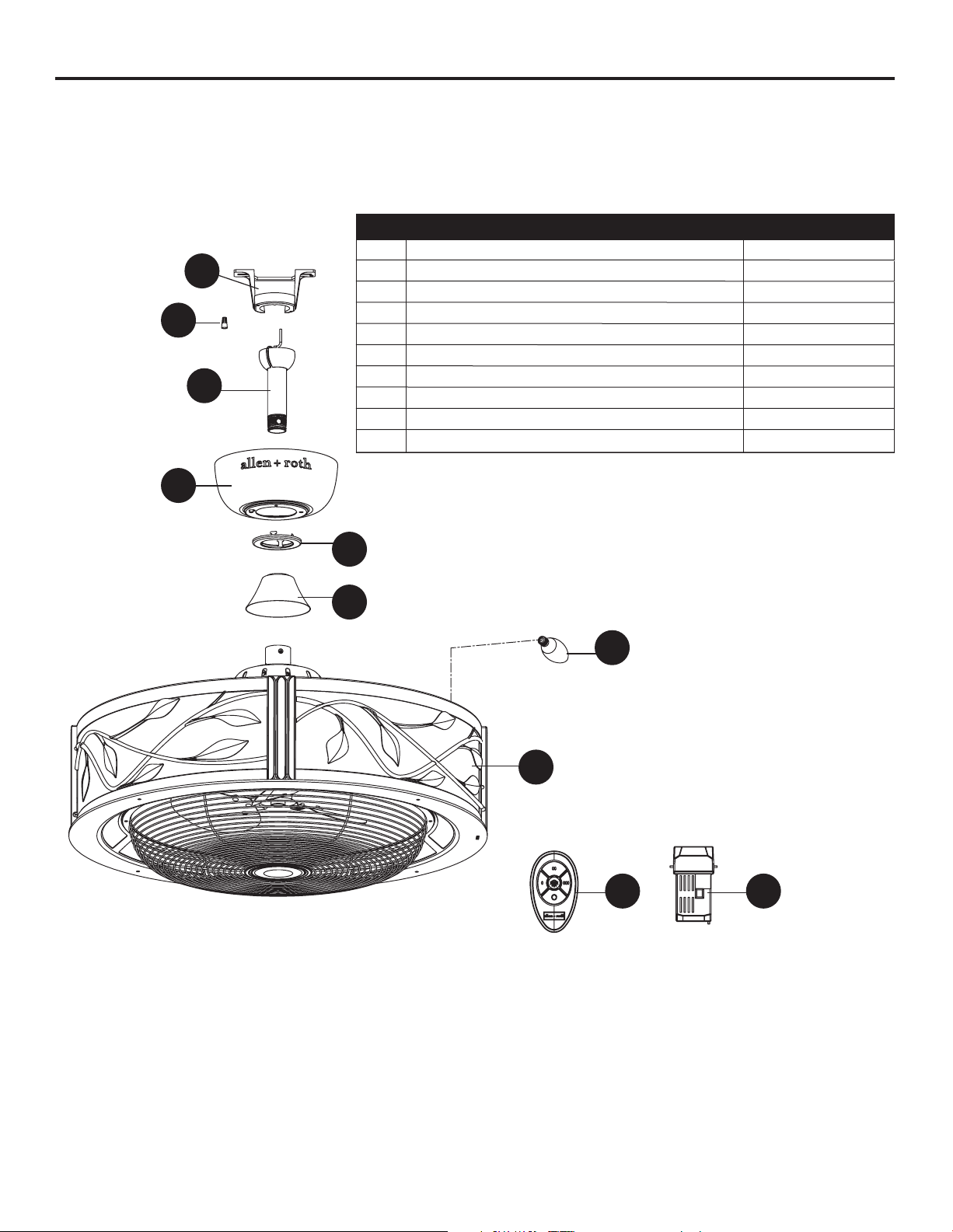
COMPONENT
SPECIFICATIONS
A
B
C
D
E
F
G
H
I
Motor Assembly
Bulb
Remote
Receiver Unit
Canopy Screw Cover
Ceiling Canopy
Hanger Ball/Downrod Assembly
Hanger Bracket
Motor Coupling Cover
3
5
6
6
7
9
10
12
13
14
15
15
17
18
3
SAFETY INFORMATION
• Before you begin installing the fan, disconnect the power by removing fuses or turning off circuit
breakers.
• Make sure that all electrical connections comply with local codes, ordinances, or the National
Electrical code. Hire a qualified electrician or consult a do-it-yourself wiring hand-book if you are
unfamiliar with installing electrical wiring.
• Make sure the installation site you choose allows a minimum clearance of 7 ft. from the blades
to the floor and at least 30 in. from the ends of the blades to any obstruction.
• If you are mounting the fan to a ceiling outlet box, use a METAL octagonal outlet box.
Secure the box directly to the building structure. The outlet box and its support must be able to
support the moving weight of the fan (at least 35 lbs.) Do NOT use a plastic outlet box.
• After you install the fan, make sure that all connections are secure to prevent the fan from falling.
• Instructions for supply connections: conductor of a fan identified as grounded conductor to be
connected to a grounded conductor of power supply; conductor of a fan identified for equipment
grounding to be connected to an equipment-grounding conductor.
Do not install or use fan if any part is damaged or missing.
WARNING
Read all instructions and safety information before installing your new fan.
Review accompanying assembly diagrams.
CAUTION
Please read and understand this entire manual before attempting to assemble, operate or install
the product. If you have any questions regarding the product, please call customer service at
1-888-567-2055,
8 a.m. - 5 p.m., EST, Monday - Friday.
• This device complies with Part 15 of the FCC Rules. Operation is subject to the following two
conditions: (1) This device may not cause harmful interference, and (2) this device must accept
any interference received, including interference that may cause undesired operation.
If the intentional radiator can be classified as a Class B digital device or a PC peripheral, then shall
include the following or equivalent:
Note: This equipment has been tested and found to comply with the limits for Class B digital
device, pursuant to part 15 of the FCC Rules. These limits are designed to provide reasonable
protection against harmful interference in a residential installation. This equipment generates, uses
and can radiate radio frequency energy and, if not installed and used in accordance with the
instructions, may cause harmful interference to radio or television reception, which can be
determined by turning the equipment off and on, the user is encouraged to try to correct the
interference by one or more of the following measures:
- Reorient or relocate the receiving antenna.
- Increase the separation between the equipment and the receiver.
- Connect the equipment into an outlet on a circuit different from that to which the receiver is
connected.
Consult the dealer or an experienced radio/TV technician for help.
Note: For a Class A digital device, statements of 15. 105(a) must be included when appropriate for
the device in question.
4
SAFETY INFORMATION (Continued)
•The net weight of this fan is: 26.01 lbs. (11.8 kg).
This fan is to be used in dry locations only.
WARNING
To reduce the risk of fire, electrical shock, or personal injury, wire connectors provided
with this fan are designed to accept only one 12 gauge house wire and two lead wires
from the fan. If your house wire is larger than 12 gauge or there is more than one house
wire to connect to the two fan lead wires, consult an electrician for the proper size wire
connectors to use.
WARNING
To reduce the risk of fire, electric shock, or personal injury, do not bend the blade arms
when installing them, balancing the blades, or cleaning the fan. Do not insert foreign
objects between the rotating fan blades. Mount to outlet box marked “ACCEPTABLE
FOR FAN SUPPORT” and use mounting screws provided with the outlet box. Most outlet
boxes commonly used for the support of lighting fixtures are not acceptable for fan sup-
port and may need to be replaced. Consult a qualified electrician if in doubt.
WARNING

5
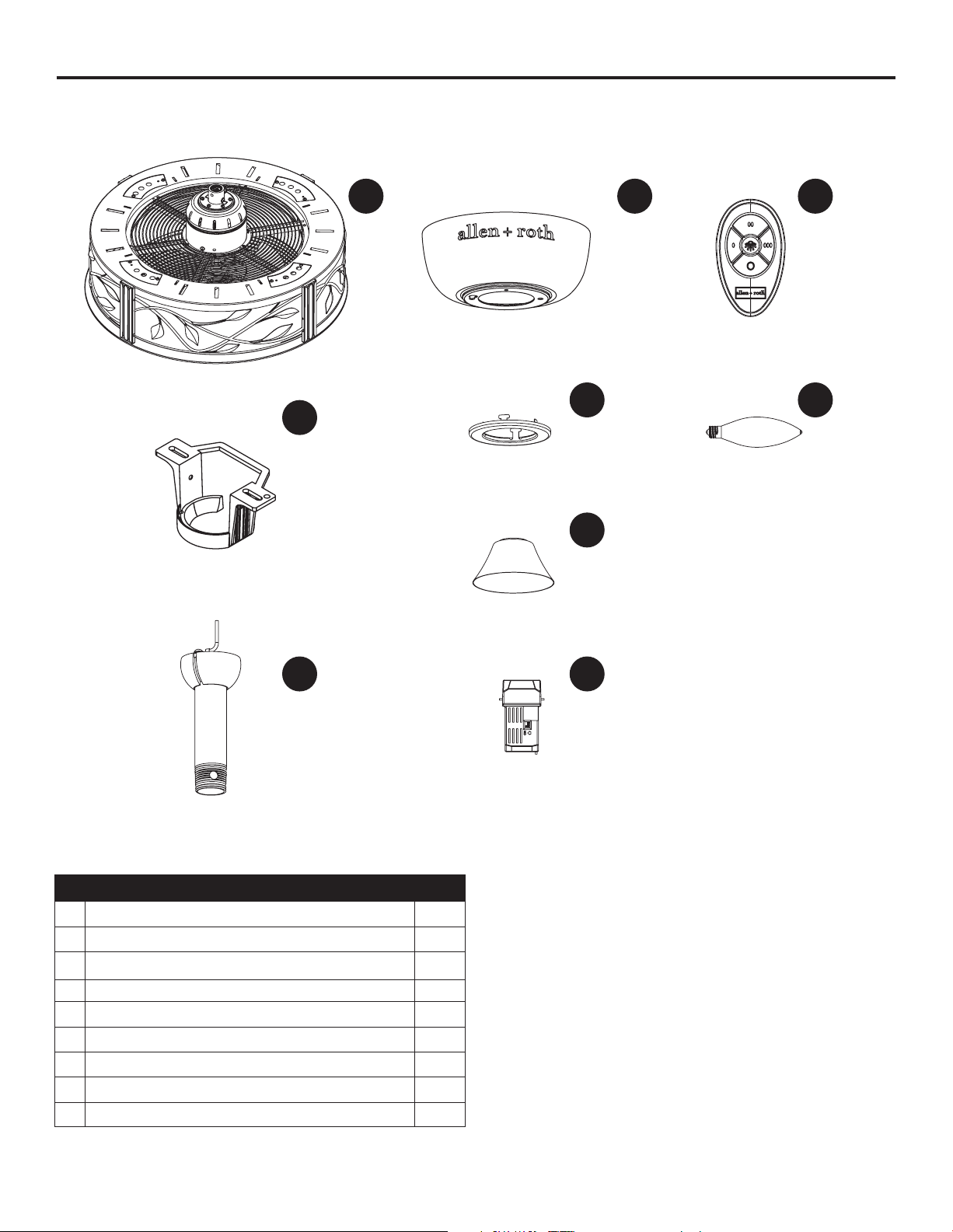
PACKAGE CONTENTS
PART DESCRIPTION QUANTITY
A Motor Assembly 1
B
Hanger Bracket
1
C
Hanger Ball / Downrod
Assembly
D
Ceiling Canopy 1
E
Canopy Screw Cover
1
F
Motor Coupling Cover
1
G
Receiver Unit
1
H
Remote
1
I
Bulb
4
A D H
IE
F
G
B
C
1
6
Wire
Connectors
Qty. 4
AA
Before beginning assembly of product, make sure all parts are present. Compare parts with.
package contents list and diagram above. If any part is missing or damaged, do not attempt to
assemble the product. Contact customer service for replacement parts.
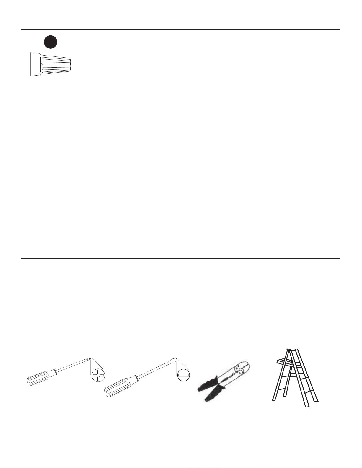
Estimated Assembly Time: 60 minutes
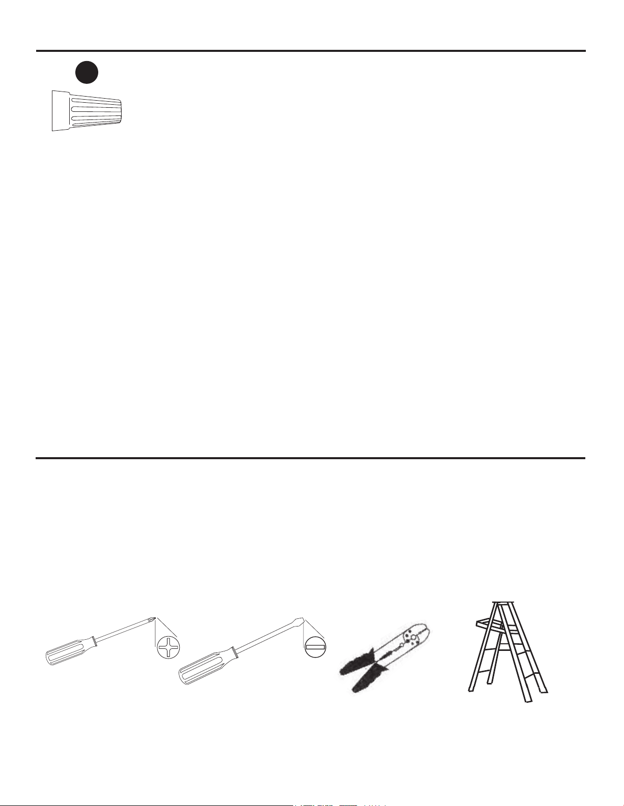
Tools Required for Assembly (not included): Phillips screwdriver, 1/4 in. flathead screwdriver,
wire stripper and step ladder.
Helpful Tools (not included): AC tester light, do-it-yourself wiring handbook and wire cutters.
PREPARATION
HARDWARE CONTENTS (shown actual size)
C
C
A
7
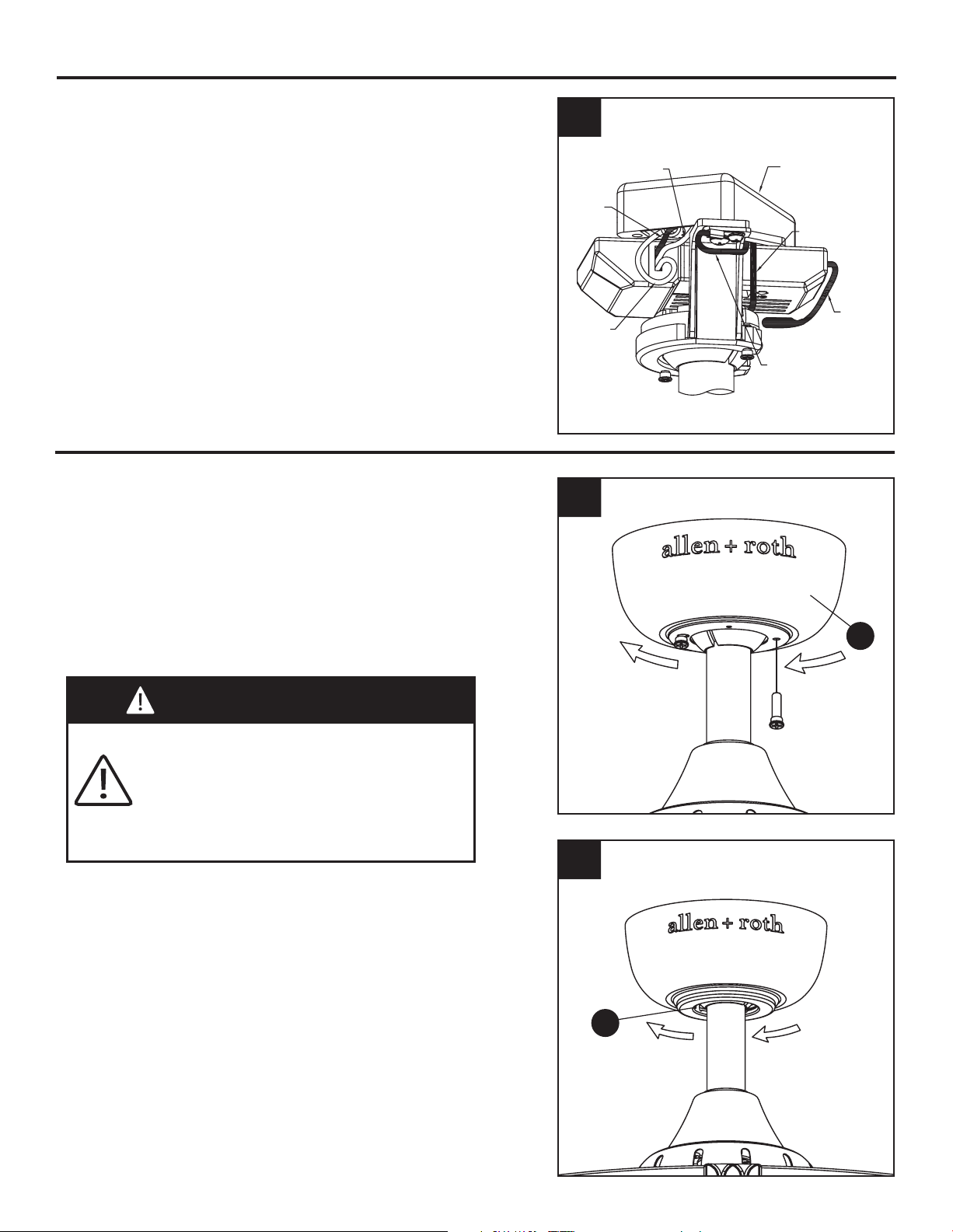
ASSEMBLY INSTRUCTIONS
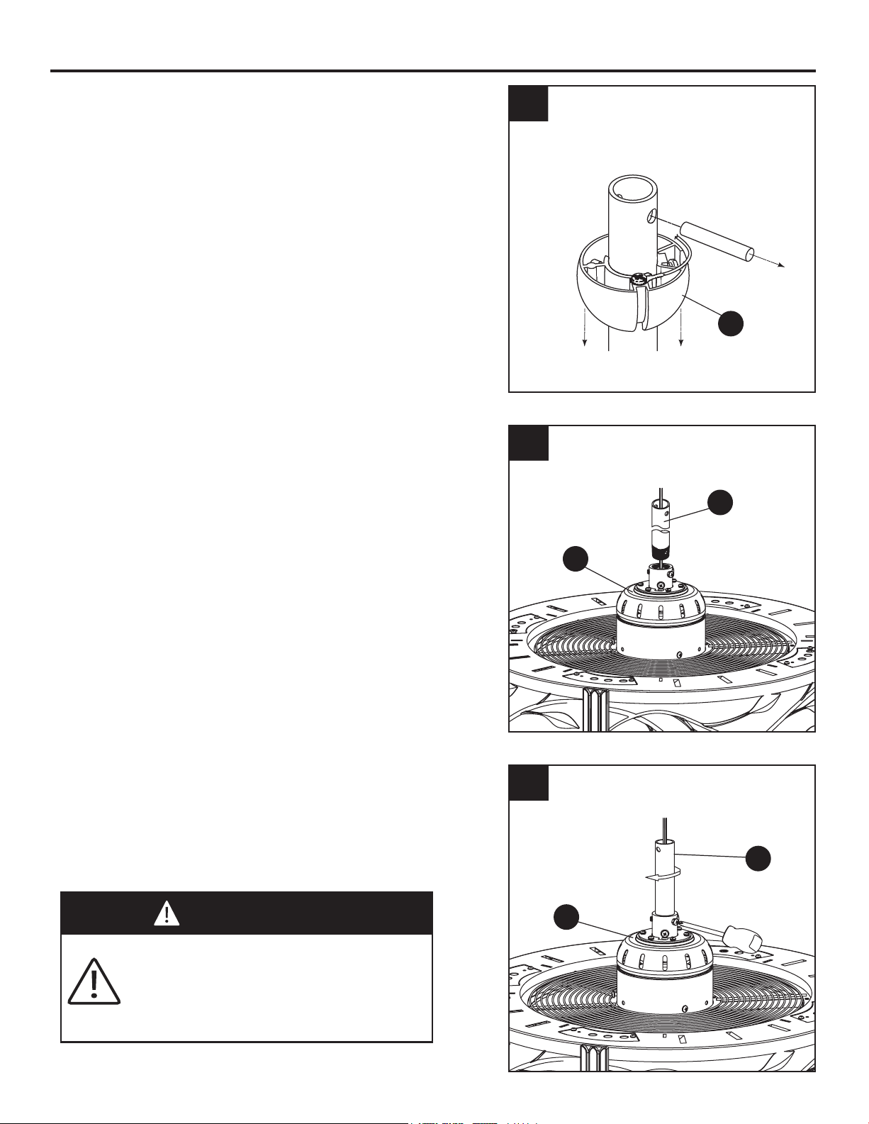
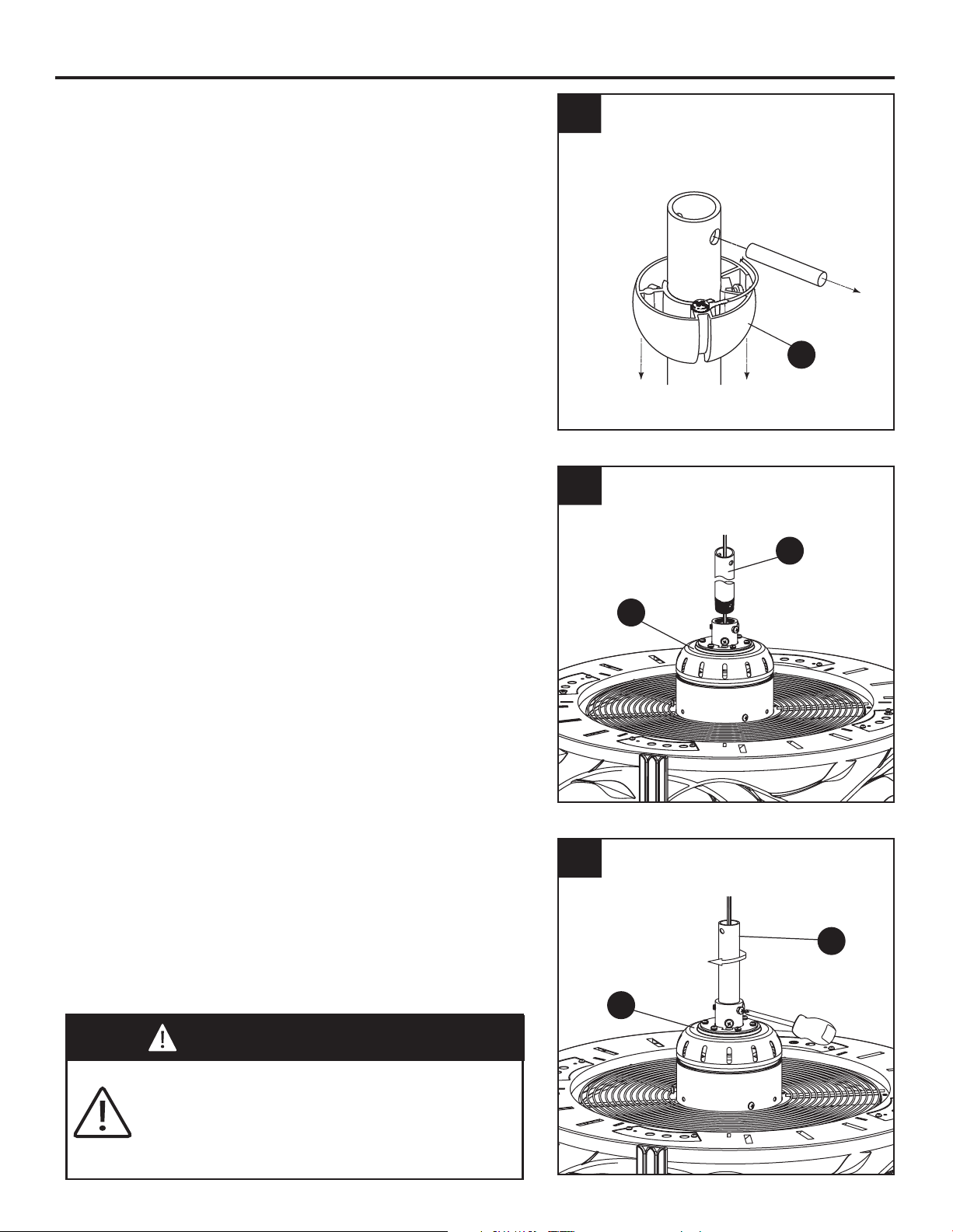
1. Remove the hanger ball portion from the
downrod/hanger ball assembly (C) by loosen-
ing the set screw in the hanger ball until the
ball falls freely down the downrod. Remove the
pin from the downrod, then remove the hanger
ball. Retain the pin and hanger ball for
reinstallation in Step 5. (Fig. 1)
1
2
3
C
A
2. Loosen the two set screws in the downrod
support of the motor assembly (A). Route the
black, white and blue wires through the
downrod of the downrod/hanger ball assembly
(C). (Fig. 2)
3. Thread the downrod of the downrod/hanger
ball assembly (C) into the downrod support
on top of the motor assembly (A). Install the
clevis pin from the downrod/hanger ball
assembly (C) by aligning the holes in the
downrod support of the motor assembly (A)
with the holes in the downrod of the
downrod/hanger ball assembly (C). Secure
clevis pin with hairpin clip from the
downrod/hanger ball assembly (C). Tighten
the two set screws in the downrod support of
the motor assembly (A). (Fig. 3)
WARNING
It is critical that the clevis pin in the
downrod support is properly installed and
the set screws is securely tightened.
Failure to do so could result in the fan
falling.
C
6
t
o
9 in
.
8
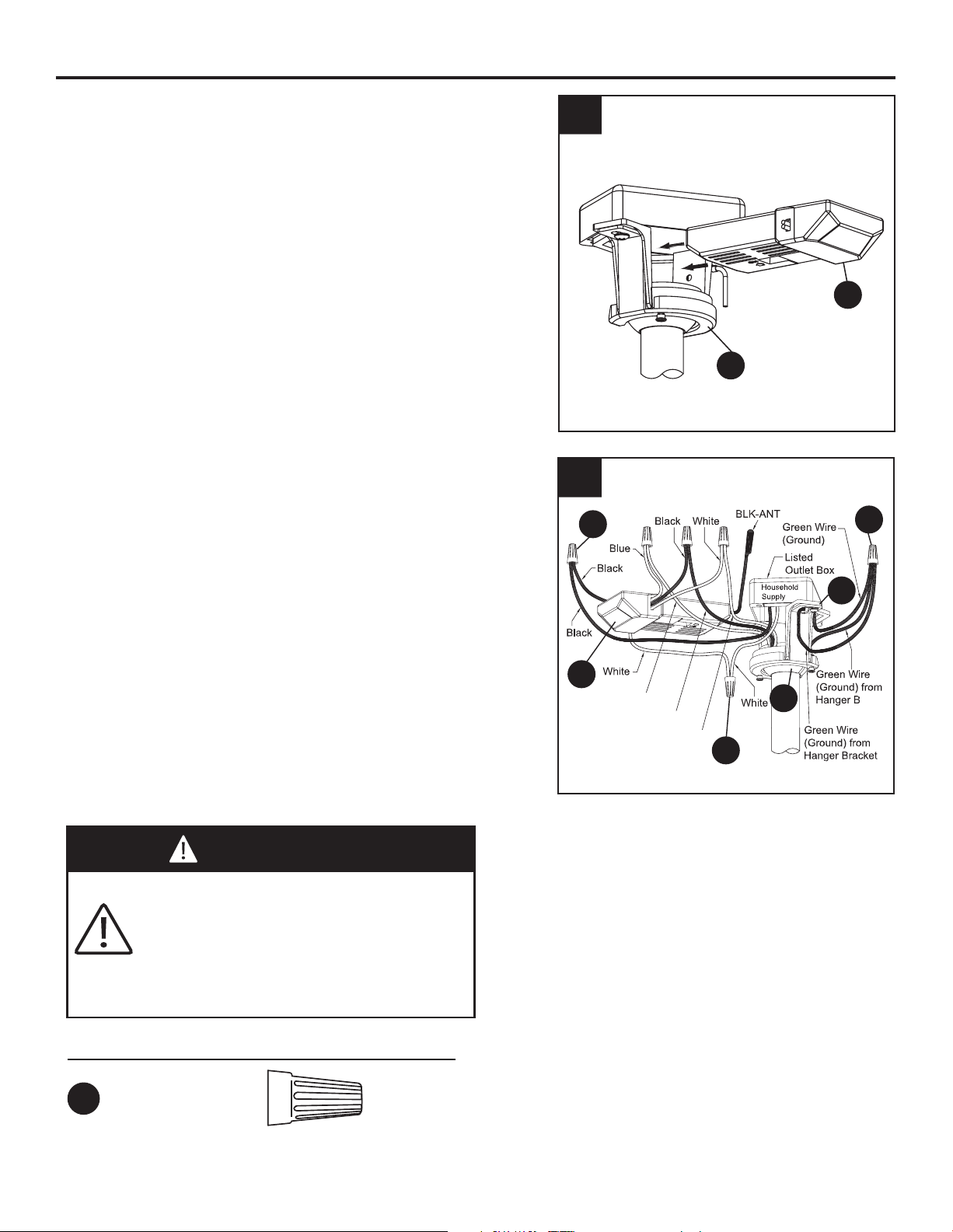
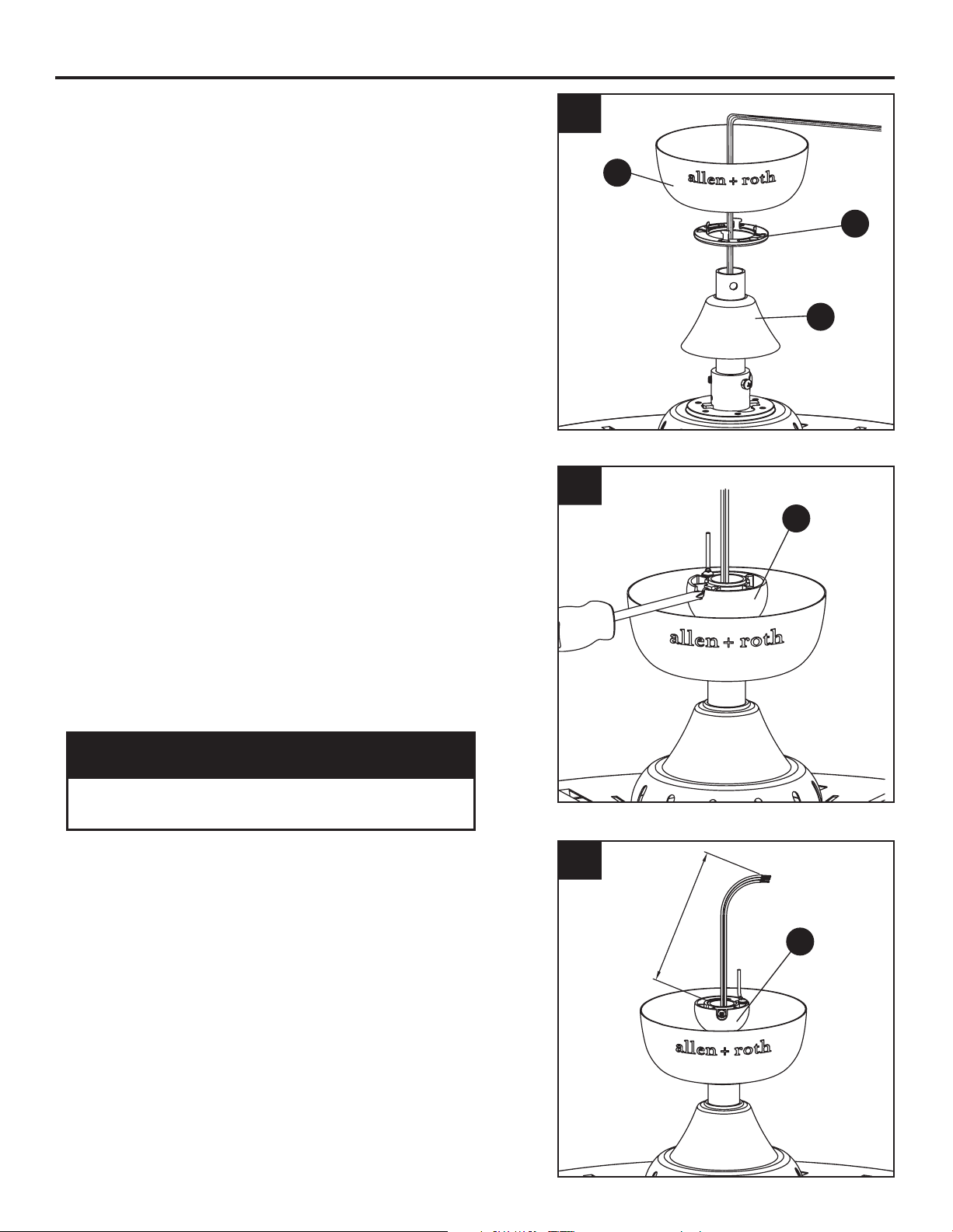
ASSEMBLY INSTRUCTIONS (Continued)
4. Route wires through motor coupling cover
(F), canopy screw cover (E) and ceiling
canopy (D). (Fig. 4)
4
E
D
C
F
5
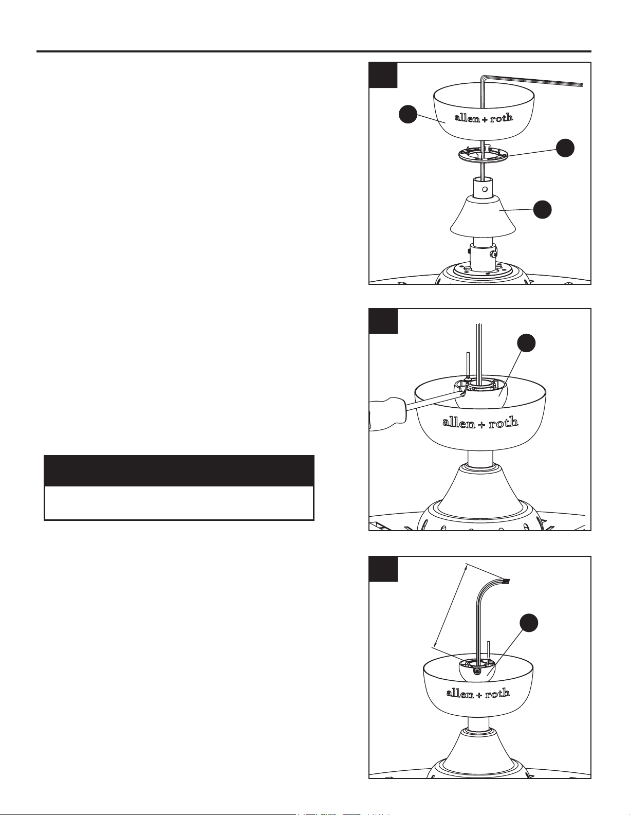
6
5. Reinstall the hanger ball on the
downrod/hanger ball assembly (C) by routing
the three 54 in. wires through the hanger ball.
Position the pin from the downrod/hanger ball
assembly (C) through the two holes in the
downrod and align the hanger ball so the pin is
captured in the groove in the top of the hanger
ball. Pull the hanger ball up tight against the
pin. Securely tighten the set screw in the
hanger ball. (Fig. 5)
CAUTION
A loose set screw could result in a wobbly
fan.
6. Cut off excess lead wire approximately 6 to 9
in. above top of the top of the downrod/hanger
ball assembly (C). Strip insulation off 1/2 in.
from the end of each lead wire. (Fig. 6)
9
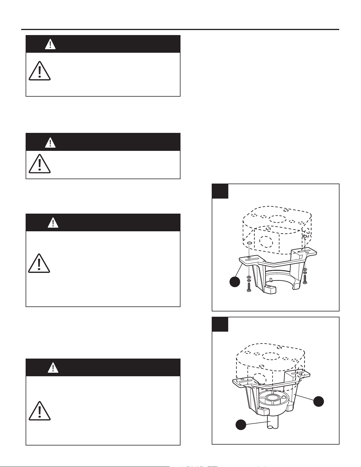
HANGING INSTRUCTIONS
WARNING
To avoid possible electrical shock, be
sure electicity is turned off at the main
fuse box before hanging.
NOTE: If you are not sure if the outlet box is
grounded, contact a licensed electrician for
advice, as it must be grounded for safe operaion.
WARNING
The fan must be hung with at least 7 ft. of
clearance from the floor to blades.
WARNING
The outlet box must be securely
anchored. Hanger bracket must seat
firmly against outlet box. If the outlet
box is recessed, remove wallboard until
bracket contacts box. If bracket and/or
outlet box are not securely attached, the
fan could wobble or fall.
B
1
1. Securely attach the hanger bracket (B) to the
outlet box using the outlet box screws and
washers supplied with the outlet box (not
included). (Fig. 1)
B
C
2
WARNING
Failure to seat tab in groove could cause
damage to electrical wires and possible
shock or fire hazard.
To avoid possible shock, do not pinch
wires between the hanger ball assembly
and the hanger bracket.
2.
Carefully lift the fan and seat the
downrod/hanger ball assembly (C) on the
hanger bracket (B) that was just attached to
the outlet box. Be sure the groove in the ball
is lined up with tab on the hanger bracket (B).
(Fig. 2)
10
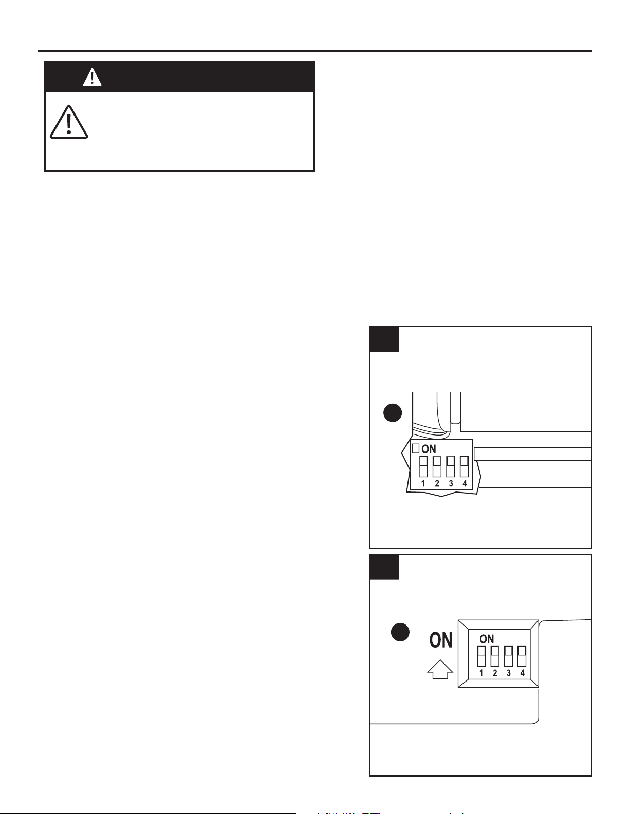
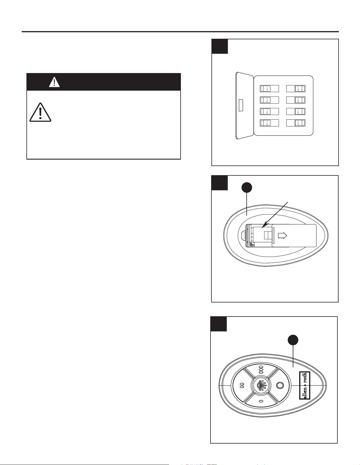
WIRING INSTRUCTIONS
H
12V
Battery
1
NOTE: If you are not sure if the outlet box is
grounded, contact a licensed electrician for
advice, as it must be grounded for safe
operation.
NOTE: The hand-held remote included with this
fan has 16 different code combinations. To
prevent possible interference from or to other
remote units, simply change the combination
code in your transmitter and receiver.
WARNING
To avoid possible electrical shock, be
sure electricity is turned off at the main
fuse box before hanging.
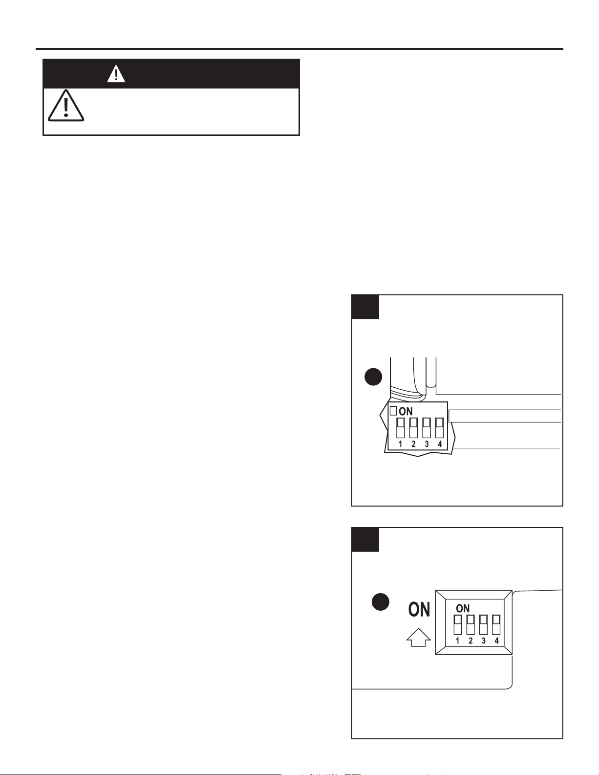
1. To set the transmitter code, remove battery
cover on remote (H) by pressing firmly below
arrow and sliding cover off. Slide code
switches to your choice of up or down position.
Factory setting is all up. Do not use this
position. With a small screwdriver or ball point
pen slide firmly up or down. Replace battery
cover on remote (H). (Fig. 1)
G
2. To set the receiver unit (G) code, slide code
switches to the same positions as set on your
remote (H). (Fig. 2)
2
11
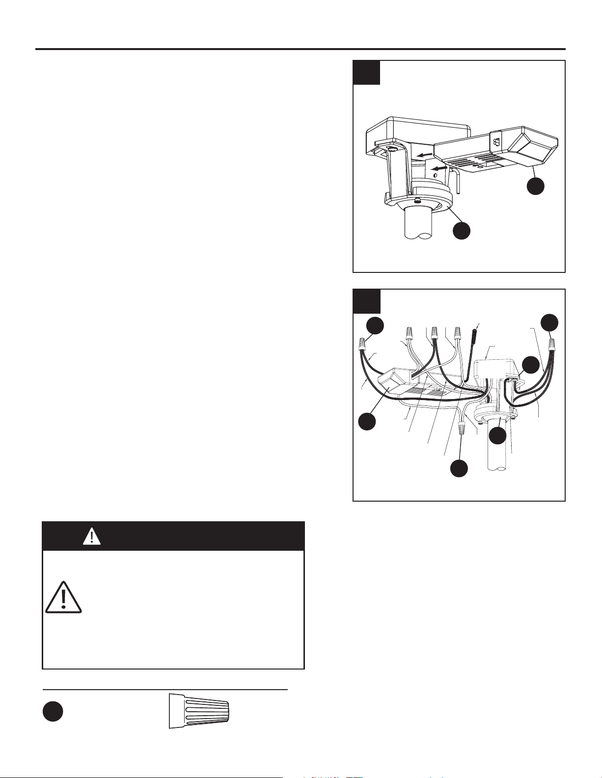
WIRING INSTRUCTIONS (Continued)
3. Slide the receiver unit (G) into the open end of
the hanger bracket (B). (Fig. 3)
G
B
3
G
B
C
AA
AA
AA
4
Blue to Light
Black to Motor
White to Motor
all
4. Connect green wires from hanger bracket (B)
and downrod/hanger ball assembly (C) to bare
(ground) wire using wire connector (AA).
Connect black wire from receiver unit (G)
marked “AC IN L” to black supply wire using wire
connector (AA).Connect white wire from
receiver unit (G) marked “AC IN N” to white
supply wire using wire connector (AA). Connect
white wire from receiver unit (G) marked “TO
MOTOR N” to white wire from fan using wire
connector supplied with receiver unit (G).
Connect black wire from receiver unit marked
“TO MOTOR L” to black wire from fan using wire
connector. Lastly, connect blue wire from
receiver unit (G) to the blue fan light
wire using
wire connector. (Fig. 4)
WARNING
Check to see that all connections are
tight, including ground, and that no bare
wire is visible at the wire connectors
except for the ground wire. Do not
operate fan until the blades are in place.
Noise and motor damage could result.
Hardware Used
AA
x 3
Wire
Connectors
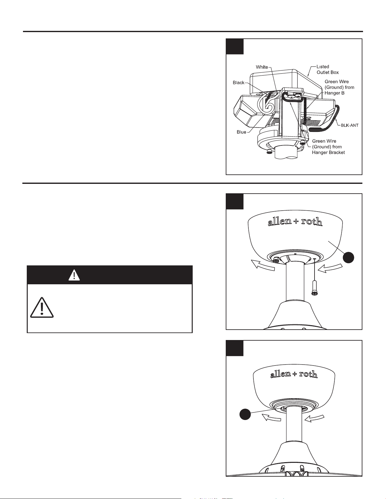
12
1
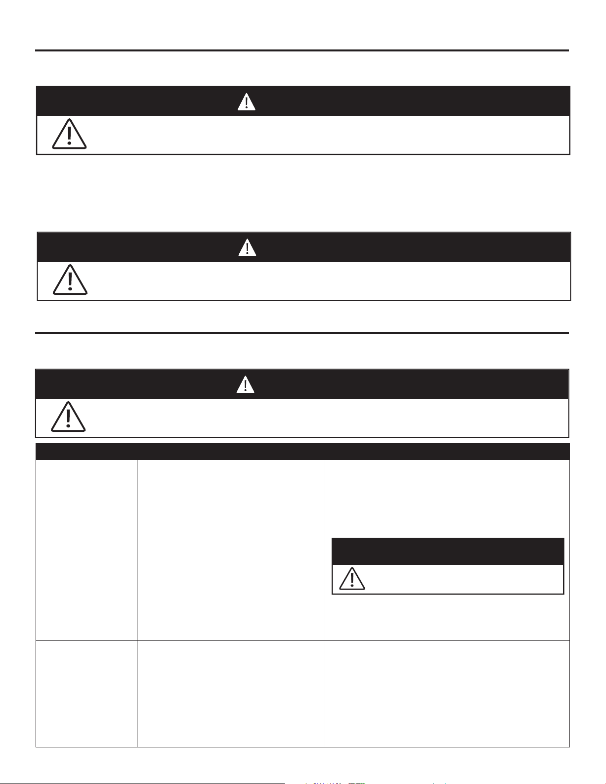
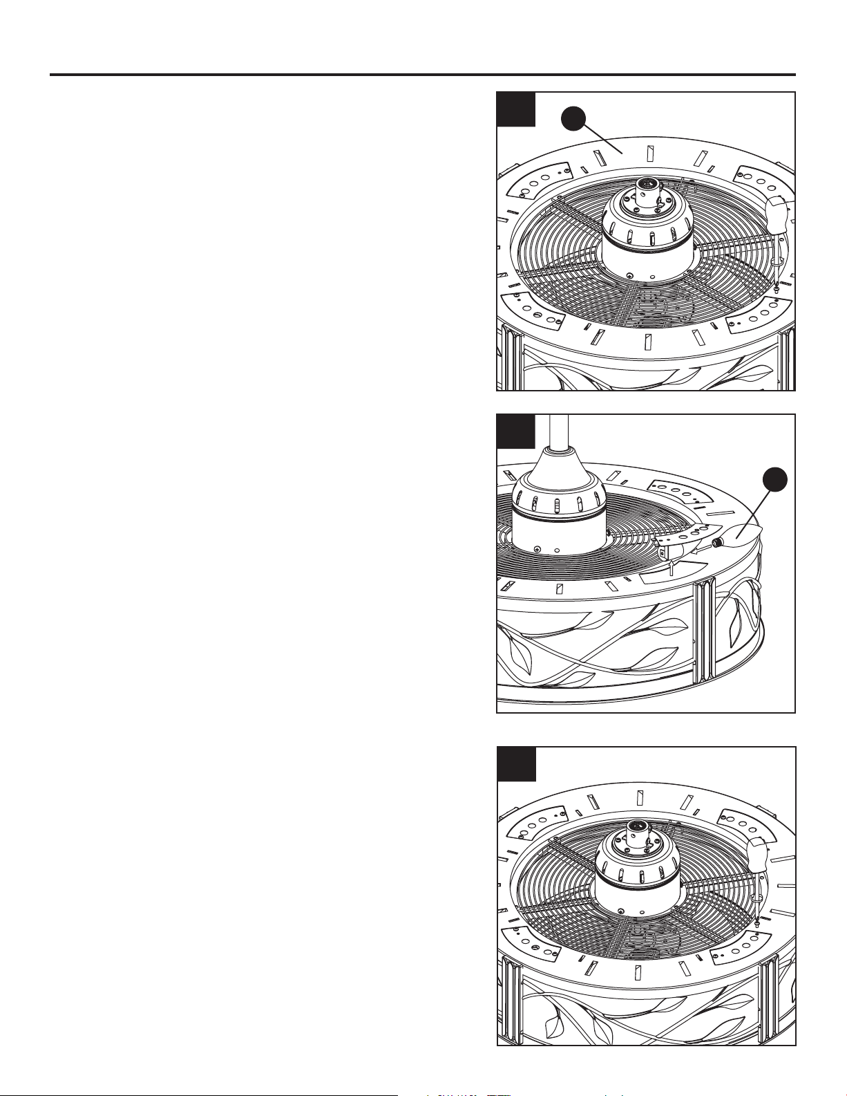
CANOPY HOUSING INSTALLATION
D
2
E
WIRING INSTRUCTIONS (Continued)
5
all
5. After connections have been made, turn leads
upward and carefully push leads into the outlet
box, with the white and green leads to one side
of the box and the black leads toward the other
side. The wires should be spread apart with the
grounded conductor and the equipment-
grounding conductor on one side of the outlet
box and the ungrounded conductor on the other
side of the outlet box. (Fig. 5)
WARNING
To avoid possible fire or shock, make
sure that the electrical wires are
completely inside the canopy housing
and not pinched between the housing
and the ceiling.
1. Remove one of the two shoulder screws in the
hanger bracket (B). Loosen the second
shoulder screw without fully removing it.
Assemble ceiling canopy (D) by rotating key
slot over shoulder screw in hanger bracket (B).
Tighten shoulder screw. Fully assemble and
tighten second shoulder screw that was
previously removed. (Fig. 1)
2. Securely attach and tighten the canopy
screw cover (E) over the shoulder screws in
the hanger bracket (B), utilizing the keyslot
twistlock feature. (Fig. 2)

13
LIGHT BULB INSTALLATION
1. Remove the screws and take off the 4 light
caps in the motor assembly (A). (Fig. 1)
1
A
I
2. Install bulbs (I). (Fig. 2)
2
3. Put the light caps back and securely tighten
the screws of light caps. (Fig. 3)
3

14
FAN OPERATING INSTRUCTIONS
3
H
2. To make fan operational, install 12-volt battery
(included) in remote (H). Store the remote
away from excessive heat or humidity. (Fig. 2)
H
2
12V BATTERY
3. The remote (H) includes five buttons for high,
medium and low fan speeds as well as fan off
and light on/off. Varying light levels are
available by holding down the light on/off
button. (Fig. 3)
WARNING
Check to see that all connections are
tight, including ground, and that no bare
wire is visible at the wire connectors,
except for the ground wire. Do not
operate fan until the blades are in place.
Noise and fan damage could result.
1. Restore electrical power to the outlet box by
turning the electricity on at the main fuse box.
(Fig.1)
1
ON
ON
ON
ON
ON
ON
ON
ON
15
TROUBLESHOOTING
Do not use water when cleaning your ceiling fan. It could damage the motor or the finish
and create the possibility of electrical shock.
WARNING
Re-lamp with the appropriate wattage bulb. Do not exceed the wattage indicated on the
bulb socket.
WARNING
•When cleaning, use only a soft brush or lint-free cloth to avoid scratching the finish.
•Abrasive cleaning agents are not required and should be avoided to prevent damage to finish.
RECOMMENDED: Periodically check that the fan motor unit screws, blade screws, support
housing and light kit screws are tight and secure.
•Periodic light dusting of the blades is recommended. A feather duster will work best.
•Avoid using water, cleansers, or harsh rag, which can warp and ruin the finish.
•Bulb Replacement: Use 40-watt candelabra-base bulbs.
CARE AND MAINTENANCE
Fan will not start
1. Fuse or circuit breaker blown.
2. Loose power line connections
to the fan, or loose switch wire
connections in the switch
housing.
3. Reversing switch in neutral
position.
1.
Check main and branch circuit fuses or
circuit breakers.
2.
Check line wire connections to fan and
switch wire connections in the switch
housings.
3.
Make sure reversing switch position is
all the way to one side.
Fan sounds
noisy
1. Blades not attached to fan
2. Loose screws in motor
housing.
3.
Screws securing fan blade
holders to motor hub are loose.
1.
Attach blades to fan before operating.
2. Check to make sure all screws in motor
housing are snug (do not overtighten).
screws which
3.
Check to make sure the
attach the fan blade holders to the motor
hub are tight.
PROBLEM POSSIBLE CAUSE CORRECTIVE ACTION
Do not install or use fan if any part is damaged or missing.
WARNING
WARNING
Make sure main power is turned off!
If you have any questions regarding the product, please call customer service at 1-888-567-2055,
8 a.m. - 5 p.m., EST, Monday - Friday.
Fan sounds
noisy
TROUBLESHOOTING (Continued)
16
4. Wire connectors inside
housing rattling.
4. Check to make sure wire connectors in
switch housing are not rattling against
each other or against the interior wall of
the switch housing.
Fan wobbles
excessively
6. Fan blades are out of
balance.
Not enough air
movement
PROBLEM POSSIBLE CAUSE CORRECTIVE ACTION
1. Set screw and nut in downrod
support is loose.
2. Set screw in downrod/hanger
ball assembly is loose.
3. Screws securing fan blade
holders to motor hub are loose.
4. Blade holders are not seated
properly.
5.
Hanger bracket and/or ceiling
outlet box is not securely fastened.
5. Motor noise caused by solid
state variable speed control.
6. Screws holding blades to
blade holders are loose.
6. Interchanging position of fan blades
can redistribute the weight and result in a
smoother operation. For example,
exchange blades in positions 1 and 3 or 1
and 4. If this does not improve wobble,
exchange 2 and 4 or 2 and 5.
1.
If possible, consider using a longer
downrod. For example, use a 12 in. downrod
instead of a 4.5 in. downrod that comes with
your fan.
Tighten both set screws and nuts
securely in downrod support.
2. Tighten the set screw in the
downrod/hanger ball assembly.
3.
Check to be sure screws which attach the
fan blade holders to the motor hub are tight.
4. Check to be sure the fan blade holders
seat firmly and uniformly to the surface of
the motor housing. If holders are seated
incorrectly, loosen the screws and
retighten.
5. Tighten the hanger bracket screws to
the outlet box, and secure outlet box.
1.
5. Some fan motors are sensitive to
signals from solid-state variable speed
controls. Solid-state controls are not
recommended, choose an alternative
control method.
6. Tighten screws securely.
WARNING
Make sure main power is turned off!
1.Too short of downrod

WARRANTY
17
The manufacturer warrants this fan to be free from defects in workmanship and material present at
time of shipment from the factory for life (with limitations) from the date of purchase. This warranty
applies only to the original purchaser. The manufacturer agrees to correct such defect at no change
or at our option replace the ceiling fan with a comparable or superior model.
To obtain warranty service, present a copy of your sales receipt as proof of purchase. All cost of
removal and reinstallation are the expressed responsibility of the purchaser. Any damage to the
ceiling fan by accident, misuse or improper installation, or by affixing accessories not produced by
this warranty, are at the purchaser’s own responsibility. The manufacturer assumes no responsibility
whatsoever for fan installation during the lifetime limited warranty. Any service performed by an
unauthorized person will render the warranty invalid.
Due to varying climatic conditions, this warranty does not cover changes in brass finish, rusting,
pitting, tarnishing, corroding or peeling. Brass finish fans maintain their beauty when protected from
varying weather conditions. Any glass provided with this fan is not covered by the warranty.
Any replacement of defective parts for the ceiling fan must be reported within the first year from the
date of purchase. For the balance of the warranty, call our customer service department at
1-888-567-2055 for return authorization and shipping instructions so that we may repair or replace
the ceiling fan. Any fan or parts returned improperly packaged is the sole responsibility of the purchaser.
There is no further expressed warranty. The manufacturer disclaims any and all implied warranties.
The duration of any implied warranty which can not be disclaimed is limited to the lifetime limited
period as specified in our warranty. The manufacturer shall not be liable for incidental, consequential
or special damages arising at or in connection with product use or performance except as may
otherwise be accorded by law. This warranty gives you specific legal rights and you also have other
rights which vary from state to state. This warranty supersedes all prior warranties.
Note: A small amount of “wobble” is normal and should not be considered a defect.
18
Printed in China
Motor Assembly AMA8074LAZ
Hanger Bracket (with Screws) APGAC110RBL
Hanger Ball/Downrod Assembly ADRACT1-45LAZ
Ceiling Canopy P807207LAZ
Canopy Screw Cover APPAC1101LAZ
Motor Coupling Cover AP1115LAZ
Receiver Unit RECAN26
Remote TR350AR
Bulb PPE12B40
Wire Connector
HDWWNUTS4
A
B
C
D
E
F
G
H
I
PART DESCRIPTION PART #
AA
B
C
D
A
I
H
G
E
F
L
AA
REPLACEMENT PARTS LIST
For replacement parts, call our customer service department at 1-888-567-2055, 8 a.m. - 5 p.m.,
EST, Monday - Friday.
ARTÍCULO #0331091
MODELO #LP8074LAZ
VENTILADOR DE TECHO EASTVIEW
Adjuntar su recibo AQUÍ
Número de serie
Fecha de Compra
¿Preguntas, problemas, piezas faltantes? Antes de volver a la tienda, llame a nuestro
Departamento de Servicio al Cliente al 1-888-567-2055, 8 a.m. - 5 pm, hora del Este, de
lunes - viernes.
ESPECIFICACIONES DEL PRODUCTO
ÍNDICE
Información de seguridad .............................................................................................................
Contenido del paquete ..................................................................................................................
Aditamentos ..................................................................................................................................
Preparación ...................................................................................................................................
Instrucciones de ensamblaje ........................................................................................................
Instrucciones para colgar ..............................................................................................................
Instrucciones de cableado ............................................................................................................
Instalación de la carcasa de la base .............................................................................................
Instalación de la bombilla .............................................................................................................
Instrucciones de funcionamiento de la cadena del tirador ............................................................
Cuidado y mantenimiento .............................................................................................................
Solución de problemas
.................................................................................................................
Garantía
........................................................................................................................................
Lista de piezas de repuesto
..........................................................................................................
20
COMPONENTE
ESPECIFICACIONES
A
B
C
D
E
F
G
H
I
Ensamble del motor
Bombilla
Control remoto
Unidad receptora
Cubierta para los tornillo de la base
Escudo del techo
Ensamble de la bola para colgar/varilla
Abrazadera para colgar
Cubierta para el acoplador del motor
21
23
24
24
25
27
28
30
31
32
33
33
35
36
21
INFORMACIÓN DE SEGURIDAD
• Antes de comenzar la instalación del ventilador, desconecte la alimentación eléctrica
retirando los fusibles o colocando el interruptor de circuito en la posición de apagado.
No instale ni use el ventilador si falta alguna pieza o si éstas están dañadas.
ADVERTENCIA
Lea todas las instrucciones y la información de seguridad antes de instalar el nuevo ventilador.
Revise los diagramas de ensamblaje adjuntos.
PRECAUCIÓN
• Asegúrese de que todas las conexiones eléctricas cumplan con los códigos locales, las
ordenanzas o el Código Nacional de Electricidad. Si no está familiarizado con la instalación del
cableado eléctrico, contrate a un electricista calificado o consulte un manual de cableado para
hacerlo usted mismo.
• Asegúrese de que el sitio de instalación que elija permita una distancia mínima de 2,13 m desde
las aspas hasta el piso y al menos a 76,20 cm desde los extremos de las aspas hasta cualquier
obstáculo.
• Si desea montar el ventilador en una caja de salida del techo, use una caja de salida octagonal
de METAL. Asegure la caja directamente a la estructura del edificio. La caja de salida y su soporte
deben ser capaces de sostener el peso del ventilador en movimiento (como mínimo 15,88 kg).
NO use una caja de salida de plástico.
• Una vez instalado el ventilador, asegúrese de que todas las conexiones sean seguras a fin de
evitar que se caiga.
• Instrucciones para las conexiones de suministro: conductor del ventilador identificado como
conductor con conexión a tierra se debe conectar al conductor con conexión a tierra de la
alimentación eléctrica; el conductor del ventilador identificado para la conexión a tierra del equipo
se debe conectar al conductor con conexión a tierra del equipo.
Lea y comprenda completamente este manual antes de intentar ensamblar, usar o instalar el
producto. Si tiene preguntas relacionadas con el producto, llame a nuestro Departamento de
Servicio al Cliente al 1-888-567-2055,
8 a.m. - 5 pm, hora del Este, de lunes - viernes.
• Este equipo cumple con lo establecido en la Parte 15 de la Normativa FCC. Su funcionamiento
está sujeto a las dos condiciones siguientes: (1) Este equipo no causará interferencias perjudiciales
y (2) este equipo tolerará cualquier interferencia recibida, incluidas las interferencias que puedan
provocar un funcionamiento no deseado. Si el radiador intencional puede ser clasificado como un
dispositivo digital de clase B o un periférico del ordenador, entonces se deberán incluir los
siguientes o equivalentes:
Nota: Tras someterlo a las pruebas correspondientes, se ha determinado que este equipo cumple
con los límites establecidos para dispositivos digitales de Clase B de conformidad con la parte 15
de la Normativa FCC. Estos límites se han establecido con el objetivo de aportar una protección
razonable contra interferencias perjudiciales cuando el equipo se utiliza en el hogar. Este equipo
genera, utiliza y puede emitir energía de radiofrecuencia y, a menos que se instale y se utilice de
acuerdo con el manual de instrucciones, puede provocar interferencias perjudiciales en las
comunicaciones por radio y televisión. Si el equipo produce interferencias perjudiciales en la
recepción de radio o televisión, lo cual puede probarse encendiendo y apagando el equipo, se
22
Para reducir el riesgo de incendios, descargas eléctricas o lesiones personales, no
doble los brazos de las aspas al instalarlas, al equilibrarlas o al limpiar el ventilador. No
introduzca objetos extraños entre las aspas en movimiento. Instale en una caja de salida
marcada como “ACCEPTABLE FOR FAN SUPPORT” (APTA PARA SOPORTE DE
VENTILADOR) y use los tornillos de montaje que se proporcionan con la caja de salida.
La mayoría de las cajas de salida que se usan comúnmente para sostener ensambles
de iluminación no son aptas para sostener un ventilador y puede ser necesario reem-
plazarlas. Si tiene dudas, consulte con un electricista calificado.
INFORMACIÓN DE SEGURIDAD (Continuación)
•El peso neto de este ventilador es: 11,8 kg (26,01 lb).
Este ventilador es apto sólo para lugares secos.
ADVERTENCIA
ADVERTENCIA
Para reducir el riesgo de incendios, descargas eléctricas o lesiones personales, los
conectores de cable incluidos con este ventilador están diseñados para soportar sólo un
cable interior de calibre 12 y dos cables conductores del ventilador. Si el cable interior es
de un calibre superior a 12 o hay más de un cable interior para conectar los dos cables
conductores del ventilador, pregúntele a un electricista cuáles son los conectores de
cable de tamaño correcto que se deben usar.
ADVERTENCIA
recomienda al usuario corregir dichas interferencias tomando una o varias de las siguientes medidas:
- Modificar la orientación o ubicación de la antena de recepción;
- Aumentar la separación entre el equipo y el receptor;
- Conectar el equipo a una toma de corriente o circuito diferente al del receptor;
Consulte al distribuidor o a un técnico especialista de radio o TV para obtener más ayuda.
Nota: Para un dispositivo digital de clase A, la declaración de 15. 105(a) debe ser incluida cuando
sea apropiada para el dispositivo en cuestión.
23
CONTENIDO DEL PAQUETE
A D H
IE
F
G
B
C
PIEZA DESCRIPCIÓN CANTIDAD
Ensamble del motor
Bombilla
Control remoto
Unidad receptora
Cubierta para los tornillo de la base
Escudo del techo
Ensamble de la bola para colgar/varilla
Abrazadera para colgar
Cubierta para el acoplador del motor
D
E
F
G
H
I
A
B
C
1
1
1
1
1
1
1
1
4
24
ADITAMENTOS
(Se muestan en tamaño real)
Conectores
de cable
Cant. 4
AA
Antes de comenzar a ensamblar el producto, asegúrese de tener todas las piezas. Compare las
piezas con la lista del contenido del paquete y el diagrama anterior. No intente ensamblar el
producto si falta alguna pieza o si éstas están dañadas. Póngase en contacto con el
Departamento de Servicio al Cliente para obtener piezas de repuesto.
Tiempo estimado de ensamblaje: 60 minutos
Herramientas necesarias para el ensamblaje (no se incluyen): Destornillador Phillips,
destornillador de punta plana de 1/4”, pinzas pelacables y escalera de tijera.
Herramientas útiles: Luz de prueba CA, manual de cableado para hacerlo usted mismo y pinzas
cortacables.
PREPARACIÓN
C
C
A
25
1
2
3
C
A
INSTRUCCIONES DE ENSAMBLAJE
1. Retire la parte correspondiente a la bola para
colgar del ensamble de la bola para
colgar/varilla(C) aflojando el tornillo de fijación
de la bola hasta que ésta salga libremente de
la varilla. Retire el pasador de la varilla y luego
retire la bola para colgar. Guarde el pasador y
la bola para colgar a fin de colocarlos nueva
mente en el Paso 5. (Fig. 1)
2. Afloje los dos tornillos de fijación del soporte
de la varilla del ensamble del motor (A). Pase
los conductores negro, blanco y azul a través
de la varilla del ensamble de la bola para
colgar/varilla (C). (Fig. 2)
3. Haga pasar la varilla del ensamble de la bola
para colgar/varilla (C) por el soporte para
varilla en la parte superior del ensamble de
motor (A). Instale el pasador de horquilla del
ensamble de la bola para colgar/varilla (C)
alineando los orificios del ensamble de
soporte de la varilla (A) con los orificios del
ensamble de la bola para colgar/varilla (C).
Fije el pasador de horquilla con el sujetador de
horquilla del ensamble de la bola para
colgar/varilla (C). Apriete los dos tornillos de
fijación del soporte de la varilla del ensamble del
motor (A). (Fig. 3)
ADVERTENCIA
Es fundamental que instale correctamente el
pasador de horquilla en el soporte de la varilla,
y que ajuste firmemente los tornillos de fijación.
El incumplimientode dicho paso
podría hacer
que el ventilador se caiga.
C
26
INSTRUCCIONES DE ENSAMBLAJE (Continuación)
4
E
D
C
F
5
6
4. Pase los cables a través de la cubierta del
acoplador del motor (F), la cubierta del tornillo
de la base (E) y la base para techo (D).
(Fig. 4)
5. Vuelva a instalar la bola para colgar en el
ensamble de la bola para colgar/varilla (C)
haciendo pasar los tres conductores de 1,37
m a través de la bola para colgar. Coloque el
pasador del ensamble de la bola para
colgar/varilla (C) a través de los dos orificios
de la varilla y alinee la bola para colgar de
manera tal que el pasador quede inserto en la
ranura de la parte superior de la bola para
colgar. Sujete la bola para colgar firmemente
al pasador. Fije bien el tornillo de fijación a la
bola para colgar. (Fig. 5)
Un tornillo de fijación flojo podría hacer que
el ventilador se tambalee.
PRECAUCIÓN
15,24 cm a
22,86 cm
6. Corte el excedente del cable conductor
aproximadamente en unos 15,24 cm a 22,86
cm por sobre la parte superior del ensamble
de la bola para colgar/varilla (C). Pele 1,27 cm
del aislamiento del extremo de cada cable
conductor. (Fig. 6)
27
INSTRUCCIONES PARA COLGAR
ADVERTENCIA
Para evitar una posible descarga
eléctrica,asegúrese de cortar la
alimentación eléctrica de la caja de
fusibles principal antes de colgar el
ventilador.
ADVERTENCIA
Debe colgar el ventilador a una distancia
mínima de 2,13 m desde las aspas hasta
el piso.
NOTA: Si no está seguro de si la caja de salida
tiene conexión a tierra, pida consejo a un
electricista certificado, ya que debe tener
conexión a tierra para un funcionamiento seguro.
B
C
2
1
B
1. Fije bien la abrazadera para colgar (B) a la
caja de salida con los tornillos y las arandelas
provistas con la caja de salida (No se incluye).
(Fig. 1)
La caja de salida debe estar bien asegu-
rada. La abrazadera para colgar debe
estar bien asentada contra la caja de
salida. Si la caja de salida está
empotrada, retire el panel hasta que la
abrazadera haga contacto con la caja. Si
la abrazadera y/o la caja de salida no
están bien aseguradas, el ventilador
podría tambalearse o caerse.
ADVERTENCIA
2. Levante cuidadosamente el ventilador y
coloque el ensamble de la bola para colgar/varilla
(C) en la abrazadera para colgar (B) que
acaba de fijar a la caja de salida. Asegúrese
de que la ranura de la bola esté alineada con
la lengüeta de la abrazadera para colgar (B). (Fig. 2)
Si no coloca la lengüeta en la ranura,
podrían dañarse los cables eléctricos y
podrían ocurrir incendios o descargas
eléctricas.
Para evitar una posible descarga
eléctrica, no apriete los cables entre el
ensamble de la bola para colgar y la
abrazadera para colgar.
ADVERTENCIA
28
H
12V
BATERÍA
1
1. Para configurar el código del transmisor (N),
retire la cubierta de la batería en el control
remoto (H) presionando firmemente bajo la
flecha y deslizando la cubierta hacia fuera.
Deslice los interruptores de código a su
elección hacia arriba o hacia abajo. La
configuración de fábrica es de todo hacia
arriba. No use esta posición. Deslice
firmemente hacia arriba o hacia abajo con un
destornillador o un bolígrafo pequeños. Vuelva
a colocar la cubierta de la batería en el control
remoto (H). (Fig. 1)
G
2. Para configurar el código de la unidad
receptora (G), deslice los interruptores de
código a la misma posición que la de su control
remoto (H). (Fig. 2)
2
INSTRUCCIONES DE CABLEADO
NOTA: El control remoto de mano incluido con el
ventilador cuenta con combinaciones de 16
códigos diferentes. Para evitar una posible
interferencia de otras unidades de control remoto
simplemente cambie la combinación de código
de su transmisor y su receptor.
Para evitar una posible descarga
eléctrica,asegúrese de cortar la
alimentación eléctrica de la caja de
fusibles principal antes de colgar el
ventilador.
ADVERTENCIA
NOTA: Si no está seguro de si la caja de salida
tiene conexión a tierra, pida consejo a un
electricista certificado, ya que debe tener
conexión a tierra para un funcionamiento seguro.
29
G
B
3
4. Conecte los conductores verdes de la
abrazadera para colgar (B) y el ensamble de
bola para colgar/varilla (C) al conductor desnudo
(a tierra) con el conector de cables (AA).
Conecte el conductor negro de la unidad
receptora (G) marcado “AC IN L” al conductor
negro de alimentación con el conector de cables
(AA). Conecte el conductor blanco de la unidad
receptora (II) marcado “AC IN N” al conductor
blanco de alimentación con el conector de cables
(AA). Conecte el conductor blanco de la unidad
receptora (G) marcado “TO MOTOR N” al
conductor blanco del ventilador con el conector
de cables incluido con la unidad
receptora (G). Conecte el conductor negro de la
unidad receptora marcado “TO MOTOR L” al
conductor negro del ventilador con el conector de
cables. Finalmente, conecte el conductor azul de
la unidad receptora (G) al conductor azul de la
iluminación del ventilador con el conector de
cables. (Fig. 4)
3. Deslice la unidad receptora (G) en el extremo
abierto de la abrazadera para colgar (B).
(Fig. 3)
INSTRUCCIONES DE CABLEADO (Continuación)
Verifique que todas las conexiones estén
ajustadas, incluida la conexión a tierra, y
que no haya conductores desnudos
visibles en los conectores, excepto el
conductor con conexión a tierra. No
opere el ventilador hasta que las aspas
estén instaladas. Podría ocasionar ruidos
y daños al motor.
ADVERTENCIA
Aditamentos utilizados
AA
x 3
Conectores
de cable
AA
AA
G
AA
4
Conductor
verde (puesta
a tierra) desde
la bola para
colgar
Azul
Azul al motor
Negro al motor
Blanco al motor
Negro
Negro
Negro a antena
Conductor verde
(puesta a tierra)
Caja de salida
homologada
Negro
Blanco
Blanco
Blanco
Suministro
eléctrico
del hogar
C
B
Conductor
verde (puesta
a tierra) desde
la abrazadera
para colgar
30
1
D
2
E
INSTRUCCIONES DE CABLEADO (Continuación)
5
Blanco
Negro
Azul
Caja de salida
homologada
Conductor
verde (puesta
a tierra) desde
la abrazadera
para colgar
Conductor verde
(puesta a tierra)
desde la bola
para colgar
Negro a
antena
5. Una vez realizadas las conexiones, gire los
conductores hacia arriba y, con cuidado,
colóquelos dentro de la caja de salida; con los
conductores blancos y verdes hacia un lado y
los conductores negros hacia el otro. Los
cables deben separarse; el conductor de
puesta a tierra y el conductor de puesta a tierra
del equipo hacia un lado de la caja de salida, y
el conductor sin puesta a tierra hacia el otro.
(Fig. 5)
INSTALACIÓN DE LA CARCASA DE LA BASE
1. Retire uno de los dos tornillos de reborde de la
abrazadera para colgar. Afloje el segundo
tornillo de reborde sin retirarlo del todo
.
Ensamble la base de techo (D) girando el
chavetero de la base (E) sobre el tornillo de
reborde de la abrazadera para colgar (B).
Apriete el tornillo de reborde. Ensamble por
completo el segundo tornillo de reborde que
antes había retirado y apriételo. (Fig. 1)
Para evitar una posible descarga
eléctrica o incendio, asegúrese de
colocar los cables eléctricos
completamente dentro de la carcasa de
la base, y de no apretarlos entre la
carcasa y el techo.
ADVERTENCIA
2. Coloque y ajuste firmemente la cubierta para
el tornillo de la base (E) sobre los tornillos de
reborde de la abrazadera para colgar
(B),
mediante el mecanismo de seguro por giro del
chavetero. (Fig. 2)
31
INSTALACIÓN DE LA BOMBILLA
1. Retire los tornillos y retire las 4 tapas de
iluminación en el ensamble del motor (A).
(Fig. 1)
1
A
I
2. Instale la bombilla (I). (Fig. 2)
2
3. Vuelva a colocar firmemente las tapas de
iluminación y apriete los tornillos de las
mismas. (Fig. 3)
3
32
3
H
2. Para que el ventilador esté operativo, instale
una batería de 12 voltios (se incluye) en el
control remoto (H). Almacene el control remoto
alejado del calor y humedad extremos. (Fig. 2)
H
2
12V BATERÍA
3. El control remoto (H) incluye cinco botones
para velocidades alta, media y baja, además
del apagado del ventilador y el
encendido/apagado de la iluminación. Podrá
acceder a diferentes niveles de iluminación al
presionar hacia abajo el botón de
encendido/apagado de la iluminación. (Fig. 3)
1
ON
ON
ON
ON
ON
ON
ON
ON
INSTRUCCIONES DE FUNCIONAMIENTO DEL VENTILADOR
1.
Restablezca la alimentación eléctrica en la
caja de salida volviendo a conectar la
electricidad de la caja de fusibles principal.
(Fig. 1)
Verifique que todas las conexiones
estén ajustadas, incluida la conexión a
tierra, y que no haya conductores
desnudos visibles en los conectores,
excepto el conductor con conexión a
tierra. No opere el ventilador hasta que
las aspas estén instaladas. Podría
ocasionar ruidos y daños al ventilador.
ADVERTENCIA
33
CUIDADO Y MANTENIMIENTO
El ventilador
no arranca
PROBLEMA CAUSA POSIBLE ACCIÓN CORRECTIVA
No use agua para limpiar el ventilador de techo. Puede dañar el motor o el acabado y
crea la posibilidad de una descarga eléctrica.
ADVERTENCIA
Por su propia seguridad, desconecte la alimentación desde la caja de fusibles o el
interruptor de circuito antes de solucionar problemas en el ventilador. No instale ni use el
ventilador si falta alguna pieza o si éstas están dañadas.
ADVERTENCIA
ADVERTENCIA
Re-lámpara con la bombilla de potencia adecuada. No exceda la potencia indicada en el
casquillo.
•El único mantenimiento que necesita el ventilador de techo es la limpieza periódica. Use sólo
una brocha suave o un paño sin pelusa para evitar rayar el acabado al limpiar. Los agentes
limpiadores abrasivos son innecesarios y deben evitarse para no dañar el acabado.
•Se recomienda una limpieza suave del polvo de las aspas periódicamente. Lo ideal es usar un
plumero de plumas. Evite usar agua, limpiadores o paños ásperos, ya que pueden arruinar el acabado.
•Sustitución de las bombillas: Use bombillas de 40 vatios candelabro de base.
El ventilador
emite mucho
ruido
1. Las aspas no están sujetas al
ventilador.
2. Hay tornillos flojos en la
carcasa del motor.
1.
Fije las aspas al ventilador antes de
ponerlo en funcionamiento.
1. Se fundió un fusible o el
interruptor de circuito.
2. Las conexiones de la línea de
alimentación eléctrica del
ventilador o las conexiones del
cable del interruptor en la carcasa
del interruptor se han aflojado.
3. El interruptor de reversa está
en la posición neutra.
1.
Verifique los fusibles del circuito de
derivación y del circuito principal o los
interruptores de circuito.
2. Verifique las conexiones del cable de
alimentación del ventilador y las
conexiones del cable del interruptor en
las carcasas del interruptor.
ADVERTENCIA
Asegúrese de cortar la
alimentación eléctrica.
3. Asegúrese de que la posición del
interruptor de reversa esté
completamente hacia un lado.
3. Los tornillos que sujetan los
soportes de las aspas del
ventilador al eje del motor están
flojos.
3. Compruebe que los tornillos que fijan
los soportes de las aspas del ventilador al
eje del motor estén ajustados.
2. Compruebe que todos los tornillos de
la carcasa del motor estén ajustados
(no apriete demasiado).
SOLUCIÓN DE PROBLEMAS
Si tiene preguntas relacionadas con el producto, llame a nuestro Departamento de Servicio al
Cliente al 1-888-567-2055, 8 a.m. - 5 pm, hora del Este, de lunes - viernes.
SOLUCIÓN DE PROBLEMAS (Continuación)
34
PROBLEMA CAUSA POSIBLE ACCIÓN CORRECTIVA
El ventilador
emite mucho
ruido
(Continuación)
ADVERTENCIA
Asegúrese de cortar la
alimentación eléctrica.
4. Los conectores de cable de la
carcasa repiquetean.
5. El control de velocidad
variable de estado sólido
produce ruidos en el motor.
6. Los tornillos que sujetan las
aspas a los soportes de las
aspas están flojos.
4. Compruebe que los conectores de
cable de la carcasa del interruptor no
repiqueteen unos contra otros o contra
las paredes interiores de la carcasa del
interruptor.
5. Algunos motores de ventilador son
sensibles a las señales de los controles de
velocidad variable de estado sólido. No se
recomiendan los controles de estado sólido,
elija un método de control alternativo.
6. Ajuste completamente los tornillos.
El ventilador
se tambalea
excesivamente
1. El tornillo de fijación y la
tuerca del soporte de la varilla
están flojos.
2. El tornillo de fijación del
ensamble de la bola para
colgar/varilla está flojo.
3. Los tornillos que sujetan los
soportes de las aspas del ventilador
al eje del motor están flojos.
1. Fije bien ambos tornillos de fijación y
sus tuercas al soporte de la varilla.
2. Apriete el tornillo de fijación en el ensamble
de la bola para colgar/varilla.
3. Compruebe que los tornillos que fijan los
soportes de las aspas del ventilador al eje
del motor estén ajustados.
4. Los soportes de las aspas no
están asentados correctamente.
5. La abrazadera para colgar y/o
la caja de salida del techo no
están firmemente ajustados.
6. Las aspas del ventilador
están desequilibradas.
4. Compruebe que los soportes de las
aspas del ventilador estén firmes y
uniformemente asentados en la superficie
de la carcasa del motor. Si los soportes no
están bien asentados, afloje los tornillos y
vuelva a ajust
arlos.
5. Aju
ste los tornillos de la abrazadera para
colgar a la caja de salida y asegúrela.
No hay
suficiente
movimiento
de aire
1.
Si es posible, piense en utilizar una
varilla más larga. Por ejemplo, use una
varilla de 30,48 cm en lugar de la varilla
de 11,43 cm provista con el ventilador.
1.La varilla es demasiado corta.
6.Intercambiar la posición de las aspas
del ventilador puede redistribuir el peso
y hacer que funcione suavemente. Por
ejemplo, intercambie las aspas en la
posición 1 y 3 ó 1 y 4. Si no mejora el
tambaleo, intercambie las posiciones 2 y
4 ó 2 y 5.

GARANTÍA
35
El fabricante garantiza, de por vida, (con limitaciones) que este ventilador no presenta defectos ni
de fabricación ni en los materiales presentes en el momento del transporte desde la fábrica a partir
de la fecha de compra. Esta garantía es válida sólo para el comprador original. El fabricante acepta
reparar dichos defectos sin cargo o, según nuestro criterio, reemplazar el ventilador de techo por un
modelo comparable o superior.
Para obtener el servicio de garantía, presente una copia del recibo de venta como prueba de la
adquisición. Todos los costos de extracción y reinstalación son responsabilidad explícita del
comprador. Cualquier daño al ventilador de techo producido por accidente, uso indebido o
instalación incorrecta, o a causa de accesorios de fijación que no están cubiertos por esta garantía,
será responsabilidad del comprador. El fabricante no asume ningún tipo de responsabilidad por la
instalación del ventilador durante la garantía limitada de por vida. Cualquier servicio realizado por
una persona no autorizada invalidará la garantía.
Debido a las cambiantes condiciones climáticas, esta garantía no cubre cambios en el acabado de
latón, óxido, picaduras, deslustre, corrosión o descascaramiento. Los ventiladores con acabado de
latón mantienen su belleza cuando se les protege de las cambiantes condiciones atmosféricas. La
garantía no cubre los elementos de vidrio incluidos con este ventilador.
El reemplazo de piezas defectuosas para el ventilador de techo debe informarse dentro del primer
año a partir de la fecha de compra. Para conocer el saldo de la garantía, llame a nuestro
Departamento de Servicio al Cliente al 1-888-567-2055 y obtenga la autorización para la devolución
y las instrucciones de envío de modo que podamos reparar o reemplazar el ventilador de techo. Un
ventilador o piezas devueltas con un embalaje incorrecto son de responsabilidad única del
comprador. No existe otro tipo de garantía explícita. El fabricante rechaza cualquiera y todas las
garantías implícitas.
La duración de cualquier garantía implícita que no pueda rechazarse se limita al período limitado de
por vida especificado en nuestra garantía. El fabricante no será responsable de daños
circunstanciales, resultantes o especiales que surjan en relación con el uso o el funcionamiento del
producto, excepto que la ley indique lo contrario. Esta garantía le da derechos legales específicos, y
además usted tiene otros derechos que varían según el estado. Esta garantía sustituye cualquier
garantía previa.
Nota: Una pequeña cantidad de “tambaleo” es normal y no se debe considerar como un defecto.

36
Impreso en China
AA
B
C
D
A
I
H
G
E
F
L
LISTA DE PIEZAS DE REPUESTO
Ensamble del motor AMA8074LAZ
Abrazadera para colgar (con tornillos) APGAC110RBL
Ensamble de la bola para colgar/varilla ADRACT1-45LAZ
Escudo del techo P807207LAZ
Cubierta para los tornillo de la base APPAC1101LAZ
Cubierta para el acoplador del motor AP1115LAZ
Unidad receptora
RECAN26
Control remoto
TR350AR
Bombilla
PPE12B40
Conectores de cable
HDWWNUTS4
A
B
C
D
E
F
G
H
I
AA
PIEZA DESCRIPCIÓN PIEZA #
Para obtener piezas de repuesto, llame a nuestro Departamento de Servicio al Cliente al al 1-888-567-
2055, 8 a.m. - 5 pm, hora del Este, de lunes - viernes.