Español p. 14
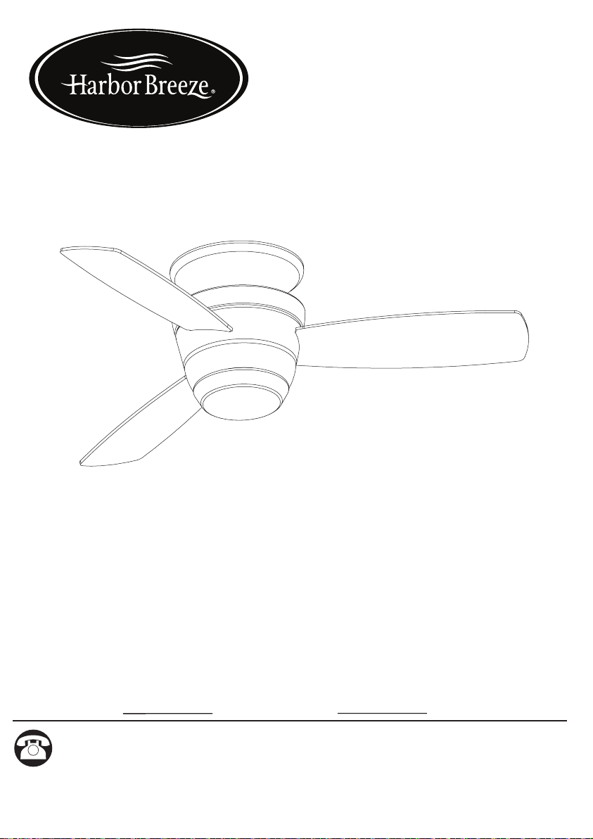
MAZON
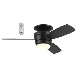
CEILING FAN
ITEM #0807421, 0807422
MODEL #00728, 00729
Serial Number Purchase Date
Harbor Breeze
®
is a registered trademark of LF,
LLC. All Rights Reserved.
Questions, problems, missing parts? Before returning to your retailer, call our
customer service department at 1-800-643-0067, 8 a.m. - 6 p.m., EST, Monday -
Thursday 8 a.m. - 5 p.m., EST Friday
PH18420
ATTACH YOUR RECEIPT HERE
UL MODEL #44-MZ

TABLE OF CONTENTS
Package Contents....................................................................................................... 3
Hardware Contents...................................................................................................... 4
Preparation.................................................................................................................. 4
Safety Information...................................................................................................... 5
Assembly Instructions..................................................................................................6
Operating Instructions ............................................................................................... 11
Care and Maintenance ............................................................................................. 12
Troubleshooting......................................................................................................... 12
Warranty..................................................................................................................................13
Replacement Parts List ............................................................................................. 13
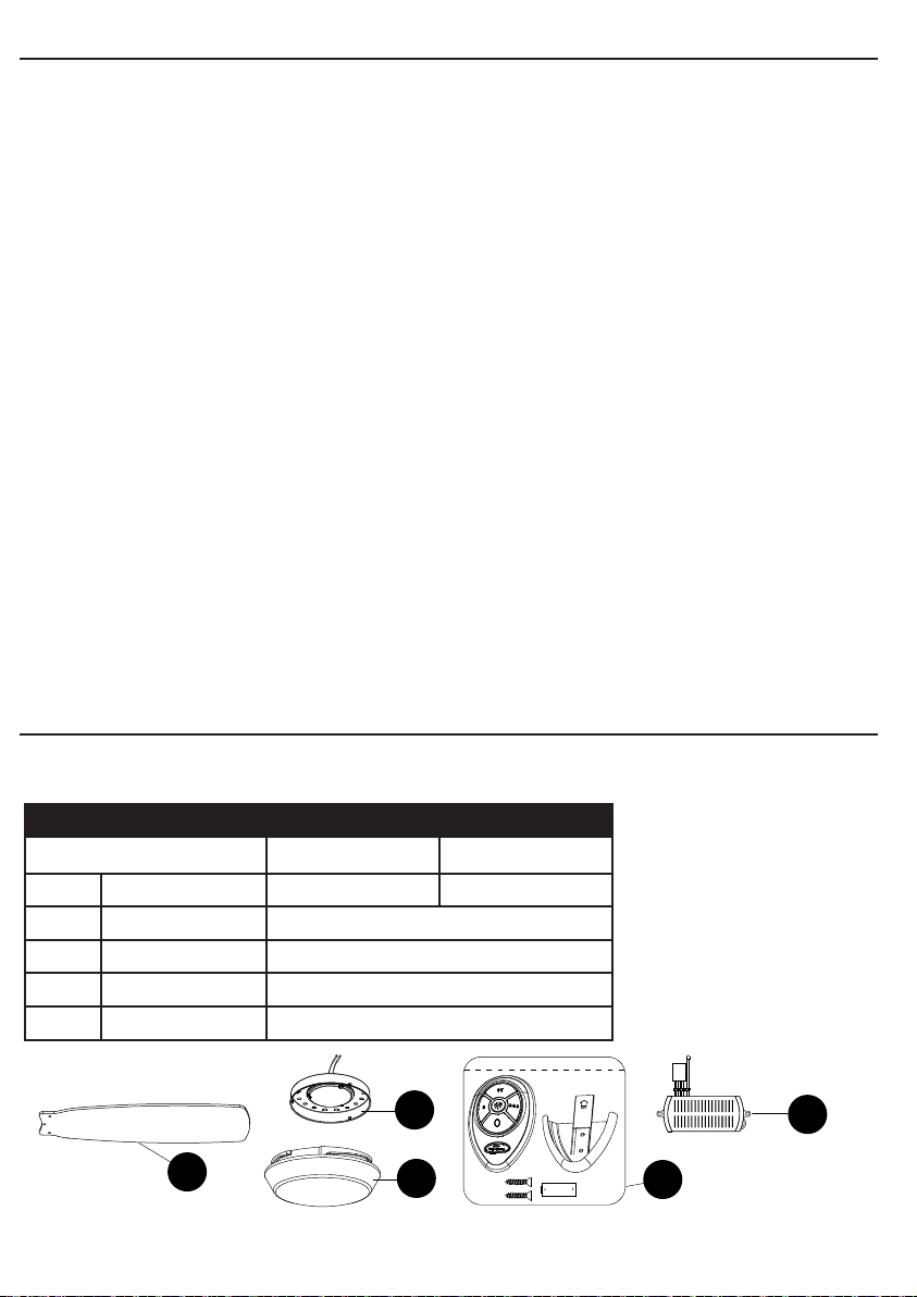
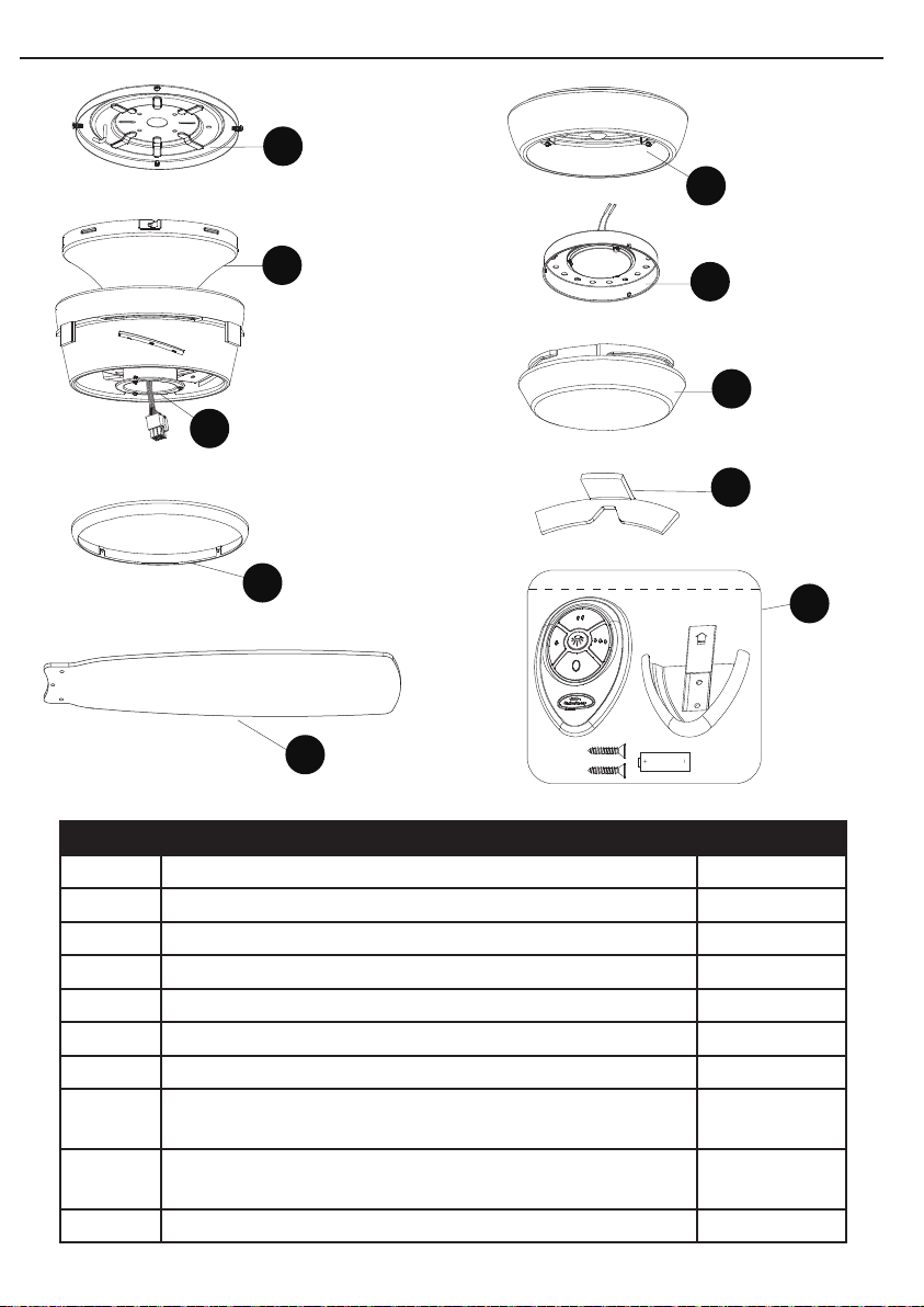
PACKAGE CONTENTS
32
A
B
H
C
D
E
F
G
I
J
PART DESCRIPTION QUANTITY
A Mounting Plate 1
B Fan Motor 1
C Trim Ring 1
D Blade 3
E Light Plate 1
F Light Fixture 1
G Glass 1
H Switch Housing Plate (preassembled to fan motor (B)) 1
I Rubber Shipping Stabalizer Tab (preassembled to fan motor (B)) 3
J Remote Pack 1
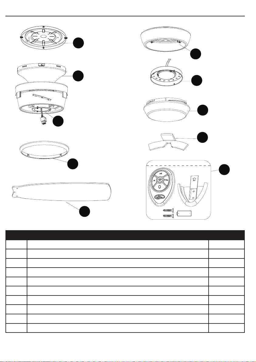
TABLE OF CONTENTS
Package Contents....................................................................................................... 3
Hardware Contents...................................................................................................... 4
Preparation.................................................................................................................. 4
Safety Information...................................................................................................... 5
Assembly Instructions..................................................................................................6
Operating Instructions ............................................................................................... 11
Care and Maintenance ............................................................................................. 12
Troubleshooting......................................................................................................... 12
Warranty..................................................................................................................................13
Replacement Parts List ............................................................................................. 13
PACKAGE CONTENTS
32
A
B
H
C
D
E
F
G
I
J
PART DESCRIPTION QUANTITY
A Mounting Plate 1
B Fan Motor 1
C Trim Ring 1
D Blade 3
E Light Plate 1
F Light Fixture 1
G Glass 1
H Switch Housing Plate (preassembled to fan motor (B)) 1
I Rubber Shipping Stabalizer Tab (preassembled to fan motor (B)) 3
J Remote Pack 1
HARDWARE CONTENTS
SAFETY INFORMATION
READ AND SAVE THESE INSTRUCTIONS
Please read and understand this entire manual before attempting to assemble, operate or install the product.
• When using an existing outlet box, be sure the box is securely attached to the building structure and can
support the full weight of the fan, so to avoid potential serious injury or death.
• All wiring must be in accordance with the National Electrical Code “ANSI/NFPA 70” and local electrical
codes. Electrical installation should be performed by a qualied licensed electrician.
• After making the wire connections, the wires should be spread apart with the grounded conductor and the
equipment-grounding conductor on one side of the outlet box and the ungrounded conductor on the other
side of the outlet box.
• All set screws must be checked and retightened during and before installation.
• Splices after being made should be turned upward and pushed carefully up into the outlet box;
• Disconnect the electrical supply circuit to the fan before installing kit.
• Electrical diagrams are for reference only.
• The net weight of this fan including the light kit is: 15.7 lbs.
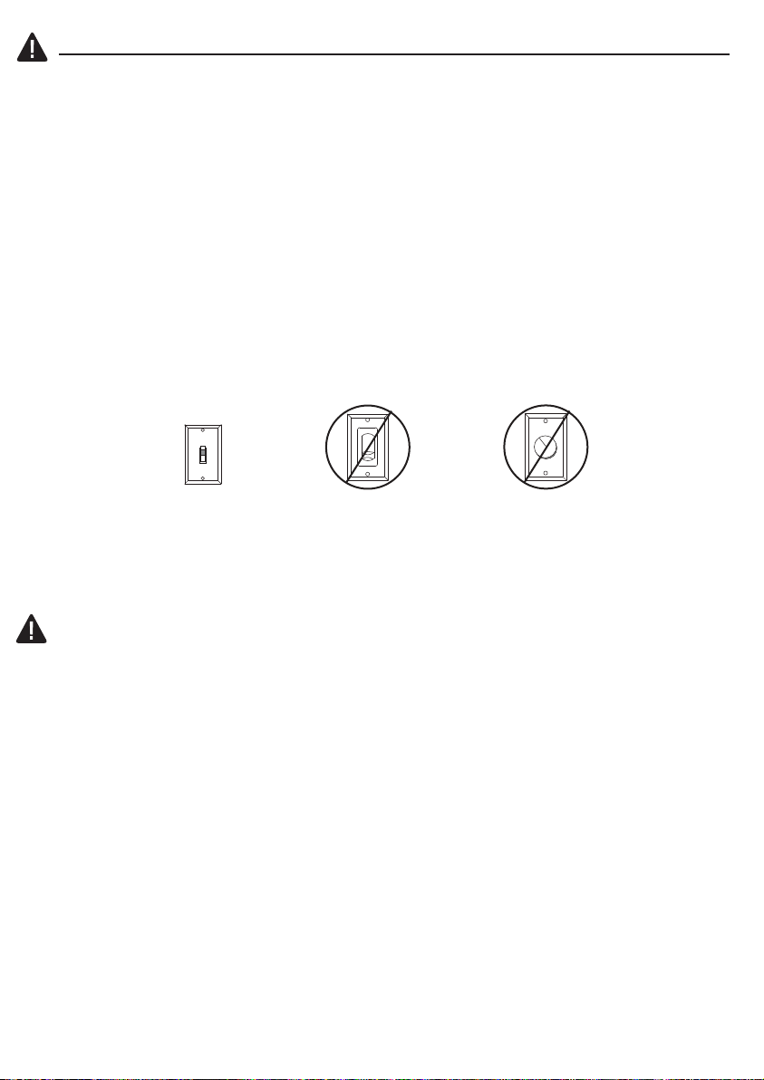
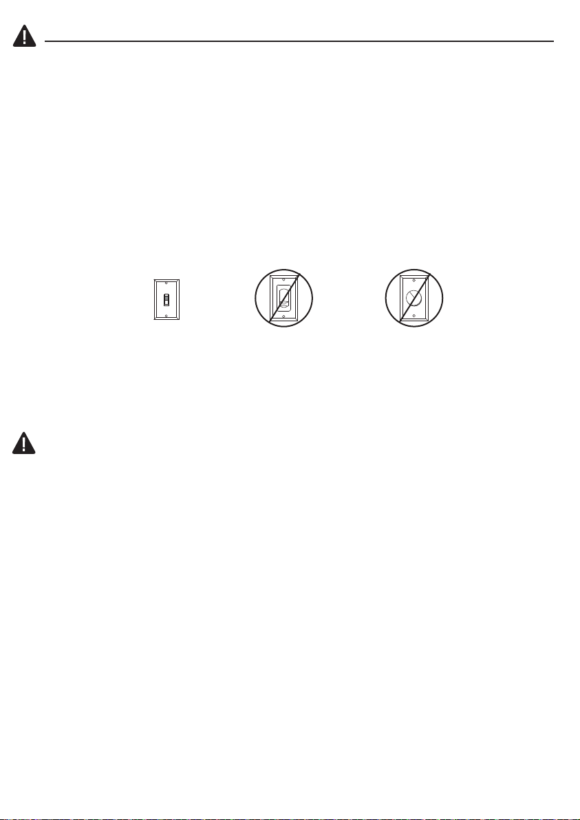
• ELECTRIC SHOCK HAZARD - Do not install this fan with variable speed wall control or wall-mounted
dimmer switch. It will permanently damage the fan’s remote control receiver and cause the fan’s functions
to fail.
WARNING
• ELECTRIC SHOCK HAZARD - To reduce the risk of electric shock, this fan must be installed with an iso-
lating wall control/switch.
• ELECTRIC SHOCK HAZARD - To reduce the risk of electric shock, make sure the electricity has bee turned
off at the circuit breaker or fuse box before beginning installation.
• PERSONAL INJURY HAZARD - To reduce the risk of injury to persons, install fan so the blades are 7 ft.
(2.1m) above the oor.
CAUTION
• PERSONAL INJURY HAZARD - To reduce the risk of personal injury, do not bend the blade brackets
when installing the brackets, balancing the blades, or cleaning the fan. DO NOT insert foreign objects in
between the rotating fan blades.
54
PREPARATION
Before beginning assembly of product, make sure all parts are present. Compare parts
with package contents list and hardware contents list. If any part is missing or damaged,
do not attempt to assemble the product.
Estimated Assembly Time: 45 minutes.
Tools Required for Assembly (not included): Phillips screwdriver, step ladder, electrical
tape, pliers, wire cutters, wire strippers.
Helpful Tools (not included): Electrical circuit tester.
This equipment has been tested and found to comply with the limits for a Class B digital device, pursuant to Part 15 of the
FCC Rules. These limits are designed to provide reasonable protection against harmful interference in a residential installation.
This equipment generates, uses and can radiate radio frequency energy and, if not installed and used in accordance with the
instructions, may cause harmful interference to radio communications. However, there is no guarantee that interference will not
occur in a particular installation. If this equipment does cause harmful interference to radio or television reception, which can be
determined by turning the equipment off and on, the user is encouraged to try to correct the interference by one or more of the
following measures:
• Reorient or relocate the receiving antenna.
• Increase the separation between the equipment and receiver.
• Connect the equipment into an outlet on a circuit different from that to which the receiver is connected.
• Consult the dealer or an experienced radio/TV technician for help.
CAUTION: Any changes or modications not expressly approved by the grantee of this device could void the user’s authority to
operate the equipment.
This device complies with Part 15 of the FCC Rules. Operation is subject to the following two conditions:
(1) This device may not cause harmful interference, and (2) this device must accept any interference received, including
interference that may cause undesired operation.
• FIRE, ELECTRIC SHOCK OR PERSONAL INJURY HAZARD - To reduce the risk of re, electric shock,
or personal injury, mount to an outlet box marked “ACCEPTABLE FOR FAN SUPPORT OF 35.1 lbs OR
LESS” and use the mounting screws provided with the outlet box. Most outlet boxes commonly used for
the support of lighting xtures are not acceptable for fan support and may need to be replaced. Consult a
qualied licensed electrician if in doubt.
ON
ON / OFF switch NO Variable speed wall control NO Dimmer switch
AA
BB
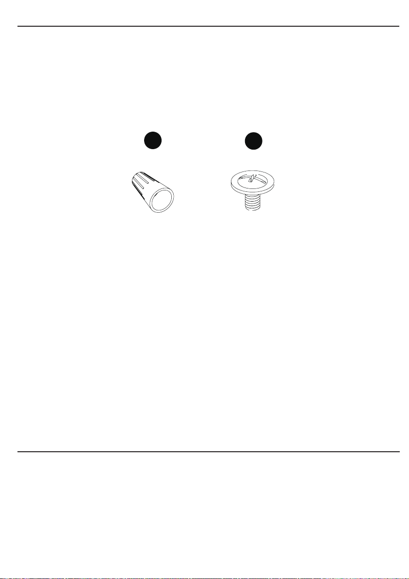
Wire Connector
Qty. 3 + 1 extra
Blade Screw
Qty. 9 + 1 extra
HARDWARE CONTENTS
SAFETY INFORMATION
READ AND SAVE THESE INSTRUCTIONS
Please read and understand this entire manual before attempting to assemble, operate or install the product.
• When using an existing outlet box, be sure the box is securely attached to the building structure and can
support the full weight of the fan, so to avoid potential serious injury or death.
• All wiring must be in accordance with the National Electrical Code “ANSI/NFPA 70” and local electrical
codes. Electrical installation should be performed by a qualied licensed electrician.
• After making the wire connections, the wires should be spread apart with the grounded conductor and the
equipment-grounding conductor on one side of the outlet box and the ungrounded conductor on the other
side of the outlet box.
• All set screws must be checked and retightened during and before installation.
• Splices after being made should be turned upward and pushed carefully up into the outlet box;
• Disconnect the electrical supply circuit to the fan before installing kit.
• Electrical diagrams are for reference only.
• The net weight of this fan including the light kit is: 15.7 lbs.
• ELECTRIC SHOCK HAZARD - Do not install this fan with variable speed wall control or wall-mounted
dimmer switch. It will permanently damage the fan’s remote control receiver and cause the fan’s functions
to fail.
WARNING
• ELECTRIC SHOCK HAZARD - To reduce the risk of electric shock, this fan must be installed with an iso-
lating wall control/switch.
• ELECTRIC SHOCK HAZARD - To reduce the risk of electric shock, make sure the electricity has bee turned
off at the circuit breaker or fuse box before beginning installation.
• PERSONAL INJURY HAZARD - To reduce the risk of injury to persons, install fan so the blades are 7 ft.
(2.1m) above the oor.
CAUTION
• PERSONAL INJURY HAZARD - To reduce the risk of personal injury, do not bend the blade brackets
when installing the brackets, balancing the blades, or cleaning the fan. DO NOT insert foreign objects in
between the rotating fan blades.
54
PREPARATION
Before beginning assembly of product, make sure all parts are present. Compare parts
with package contents list and hardware contents list. If any part is missing or damaged,
do not attempt to assemble the product.
Estimated Assembly Time: 45 minutes.
Tools Required for Assembly (not included): Phillips screwdriver, step ladder, electrical
tape, pliers, wire cutters, wire strippers.
Helpful Tools (not included): Electrical circuit tester.
This equipment has been tested and found to comply with the limits for a Class B digital device, pursuant to Part 15 of the
FCC Rules. These limits are designed to provide reasonable protection against harmful interference in a residential installation.
This equipment generates, uses and can radiate radio frequency energy and, if not installed and used in accordance with the
instructions, may cause harmful interference to radio communications. However, there is no guarantee that interference will not
occur in a particular installation. If this equipment does cause harmful interference to radio or television reception, which can be
determined by turning the equipment off and on, the user is encouraged to try to correct the interference by one or more of the
following measures:
• Reorient or relocate the receiving antenna.
• Increase the separation between the equipment and receiver.
• Connect the equipment into an outlet on a circuit different from that to which the receiver is connected.
• Consult the dealer or an experienced radio/TV technician for help.
CAUTION: Any changes or modications not expressly approved by the grantee of this device could void the user’s authority to
operate the equipment.
This device complies with Part 15 of the FCC Rules. Operation is subject to the following two conditions:
(1) This device may not cause harmful interference, and (2) this device must accept any interference received, including
interference that may cause undesired operation.
• FIRE, ELECTRIC SHOCK OR PERSONAL INJURY HAZARD - To reduce the risk of re, electric shock,
or personal injury, mount to an outlet box marked “ACCEPTABLE FOR FAN SUPPORT OF 35.1 lbs OR
LESS” and use the mounting screws provided with the outlet box. Most outlet boxes commonly used for
the support of lighting xtures are not acceptable for fan support and may need to be replaced. Consult a
qualied licensed electrician if in doubt.
ON
ON / OFF switch NO Variable speed wall control NO Dimmer switch
AA
BB
Wire Connector
Qty. 3 + 1 extra
Blade Screw
Qty. 9 + 1 extra
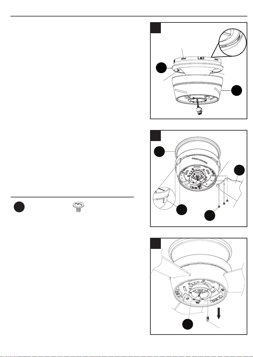
ASSEMBLY INSTRUCTIONS
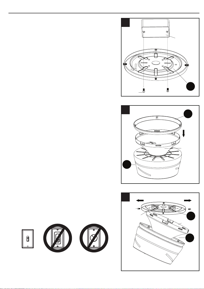
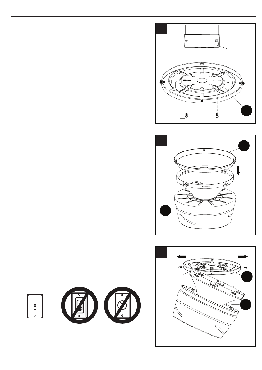
1. Attach mounting plate (A) to outlet box (not
included) using two screws (not included).
Securely tighten two outlet box screws. Pull
black, white, and grounded wires out of outlet
box and through the hole in the mounting
plate (A).
2. Place trim ring (C) over canopy, and lay it on
fan motor (B).
3. Loosen two preassembled screws across from
each other on the mounting plate (A). Remove
and save remaining two preassembled
screws. Hang fan motor (B) on mounting plate
(A) hook using one of the non-slotted holes in
the canopy.
76
A
Outlet
box
Screw
1
Ground/
Green
White
Black
Green/
Grounded
Black
Black
White
Green
Outlet box
Receiver
White
Supply
Circuit
4
AA
5
B
A
Screw
6
B
C
Canopy
2
A
B
Canopy
Screw
Hook
3
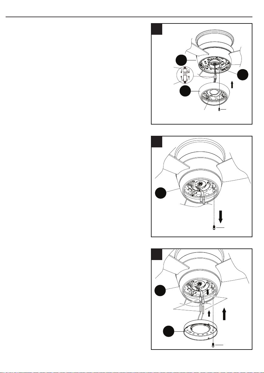
ASSEMBLY INSTRUCTIONS
6. Align keyhole slots on the fan motor (B) with
the protruding screw heads on the mounting
plate (A). Lift the fan motor (B) up to the
mounting plate (A), making sure not to break
any wire connections. Rotate the fan motor
(B) clockwise until the screw heads fully
engage into keyhole slots. Insert the previously
removed screws (Step 3, page 6) and securely
tighten all the screws.
IMPORTANT: Do NOT use this fan with a
dimmer switch or variable speed wall control.
Using a dimmer switch or variable speed wall
control will damage the fan.
ON
ON / OFF
switch
NO Variable
speed wall
control
NO Dimmer
switch
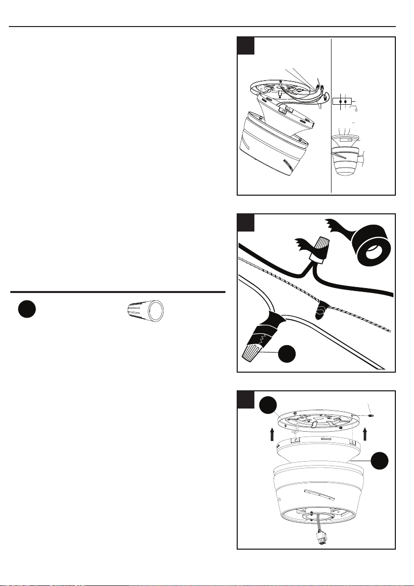
4. Connect the BLACK wire from the fan to
the BLACK wire from the ceiling. Connect
the WHITE wire from the fan, to the WHITE
wire from the ceiling. Connect all GROUND
(GREEN) wires from the fan together to the
GREEN/BARE wire from ceiling. Connecting
the GREEN/GROUND wires is conducive to
receive the signal of the remote control.
NOTE: The BLACK wire is the hot power for the
fan and light kit. The WHITE wire is common for
fan and light kit. GREEN wire is the ground wire.
lf the household wires are different colors than
referred to above, stop immediately and consult a
professional electrician to determine proper wiring.
5. Twist wire ends together and screw wire
connectors (AA) on in a clockwise direction.
Tape wire connectors (AA) and wires together
with electrical tape (not included).
Hardware Used
x 3
Wire Connector
AA
ASSEMBLY INSTRUCTIONS
1. Attach mounting plate (A) to outlet box (not
included) using two screws (not included).
Securely tighten two outlet box screws. Pull
black, white, and grounded wires out of outlet
box and through the hole in the mounting
plate (A).
2. Place trim ring (C) over canopy, and lay it on
fan motor (B).
3. Loosen two preassembled screws across from
each other on the mounting plate (A). Remove
and save remaining two preassembled
screws. Hang fan motor (B) on mounting plate
(A) hook using one of the non-slotted holes in
the canopy.
76
A
Outlet
box
Screw
1
Ground/
Green
White
Black
Green/
Grounded
Black
Black
White
Green
Outlet box
Receiver
White
Supply
Circuit
4
AA
5
B
A
Screw
6
B
C
Canopy
2
A
B
Canopy
Screw
Hook
3
ASSEMBLY INSTRUCTIONS
6. Align keyhole slots on the fan motor (B) with
the protruding screw heads on the mounting
plate (A). Lift the fan motor (B) up to the
mounting plate (A), making sure not to break
any wire connections. Rotate the fan motor
(B) clockwise until the screw heads fully
engage into keyhole slots. Insert the previously
removed screws (Step 3, page 6) and securely
tighten all the screws.
IMPORTANT: Do NOT use this fan with a
dimmer switch or variable speed wall control.
Using a dimmer switch or variable speed wall
control will damage the fan.
ON
ON / OFF
switch
NO Variable
speed wall
control
NO Dimmer
switch
4. Connect the BLACK wire from the fan to
the BLACK wire from the ceiling. Connect
the WHITE wire from the fan, to the WHITE
wire from the ceiling. Connect all GROUND
(GREEN) wires from the fan together to the
GREEN/BARE wire from ceiling. Connecting
the GREEN/GROUND wires is conducive to
receive the signal of the remote control.
NOTE: The BLACK wire is the hot power for the
fan and light kit. The WHITE wire is common for
fan and light kit. GREEN wire is the ground wire.
lf the household wires are different colors than
referred to above, stop immediately and consult a
professional electrician to determine proper wiring.
5. Twist wire ends together and screw wire
connectors (AA) on in a clockwise direction.
Tape wire connectors (AA) and wires together
with electrical tape (not included).
Hardware Used
x 3
Wire Connector
AA
98
ASSEMBLY INSTRUCTIONS
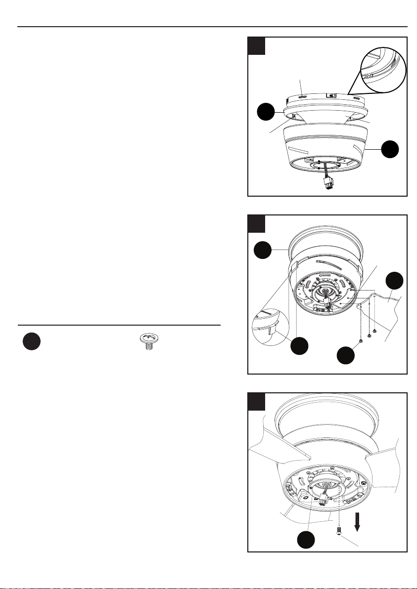
7. Align the notches on the fan motor (B) canopy
with raised areas inside the trim ring (C). Pop
the trim ring (C) into the canopy.
8. Remove and discard preassembled rubber
shipping stabilizer tabs (I) from fan motor (B).
Insert blade (D) into slot on fan motor (B).
Secure blade (D) with three blade screws
(BB). Repeat for remaining blades (D) and
blade screws (BB).
9. Loosen two screws from switch housing
plate (H). Remove and save remaining
screw.
B
C
Canopy
Notch
Raised
area
7
D
BB
I
B
Slot
8
H
Screw
9
ASSEMBLY INSTRUCTIONS
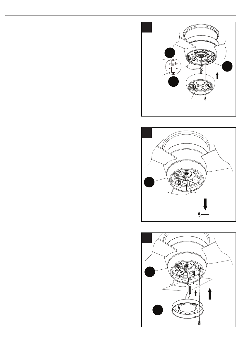
10. Connect the 9-pin plug exiting the bottom of
the fan motor (B) to the 9-pin plug from the
light plate (E). Be sure plugs snap together
completely. Attach light plate (E) to switch
housing plate (H). Align keyholes, then twist to
lock. Replace previously removed screw (Step
9, page 8) and securely tighten all screws.
11. Loosen two preassembled screws from
light plate (E). Remove and save remaining
preassembled screw from light plate (E).
12. Connect the WHITE wire from the light
plate (E) to the WHITE wire from the light
xture (F). Connect the BLUE wire from
the light plate (E) to the BLUE wire from
the light xture (F). Align the keyhole
slots on the light xture and the light
plate (E), and twist to lock. Replace the
previously removed screw (Step 11, page
9) and securely tighten all of the screws.
H
B
E
Keyslot hole
Screw
Female
plug
Male
plug
10
Screw
E
11
Screw
E
F
White
Blue
12
Hardware Used
Blade Screw x 9
BB
98
ASSEMBLY INSTRUCTIONS
7. Align the notches on the fan motor (B) canopy
with raised areas inside the trim ring (C). Pop
the trim ring (C) into the canopy.
8. Remove and discard preassembled rubber
shipping stabilizer tabs (I) from fan motor (B).
Insert blade (D) into slot on fan motor (B).
Secure blade (D) with three blade screws
(BB). Repeat for remaining blades (D) and
blade screws (BB).
9. Loosen two screws from switch housing
plate (H). Remove and save remaining
screw.
B
C
Canopy
Notch
Raised
area
7
D
BB
I
B
Slot
8
H
Screw
9
ASSEMBLY INSTRUCTIONS
10. Connect the 9-pin plug exiting the bottom of
the fan motor (B) to the 9-pin plug from the
light plate (E). Be sure plugs snap together
completely. Attach light plate (E) to switch
housing plate (H). Align keyholes, then twist to
lock. Replace previously removed screw (Step
9, page 8) and securely tighten all screws.
11. Loosen two preassembled screws from
light plate (E). Remove and save remaining
preassembled screw from light plate (E).
12. Connect the WHITE wire from the light
plate (E) to the WHITE wire from the light
xture (F). Connect the BLUE wire from
the light plate (E) to the BLUE wire from
the light xture (F). Align the keyhole
slots on the light xture and the light
plate (E), and twist to lock. Replace the
previously removed screw (Step 11, page
9) and securely tighten all of the screws.
H
B
E
Keyslot hole
Screw
Female
plug
Male
plug
10
Screw
E
11
Screw
E
F
White
Blue
12
Hardware Used
Blade Screw x 9
BB
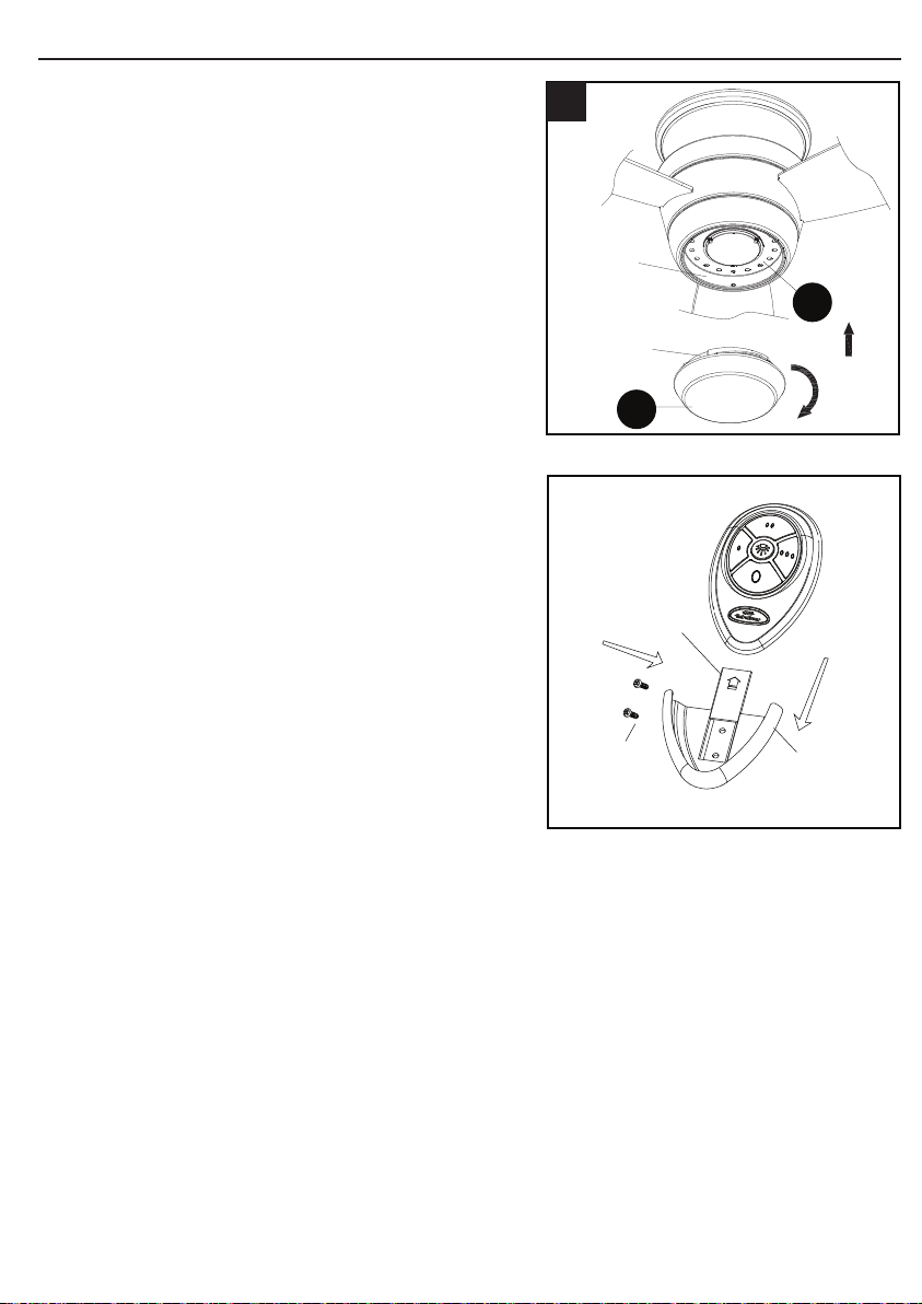
11
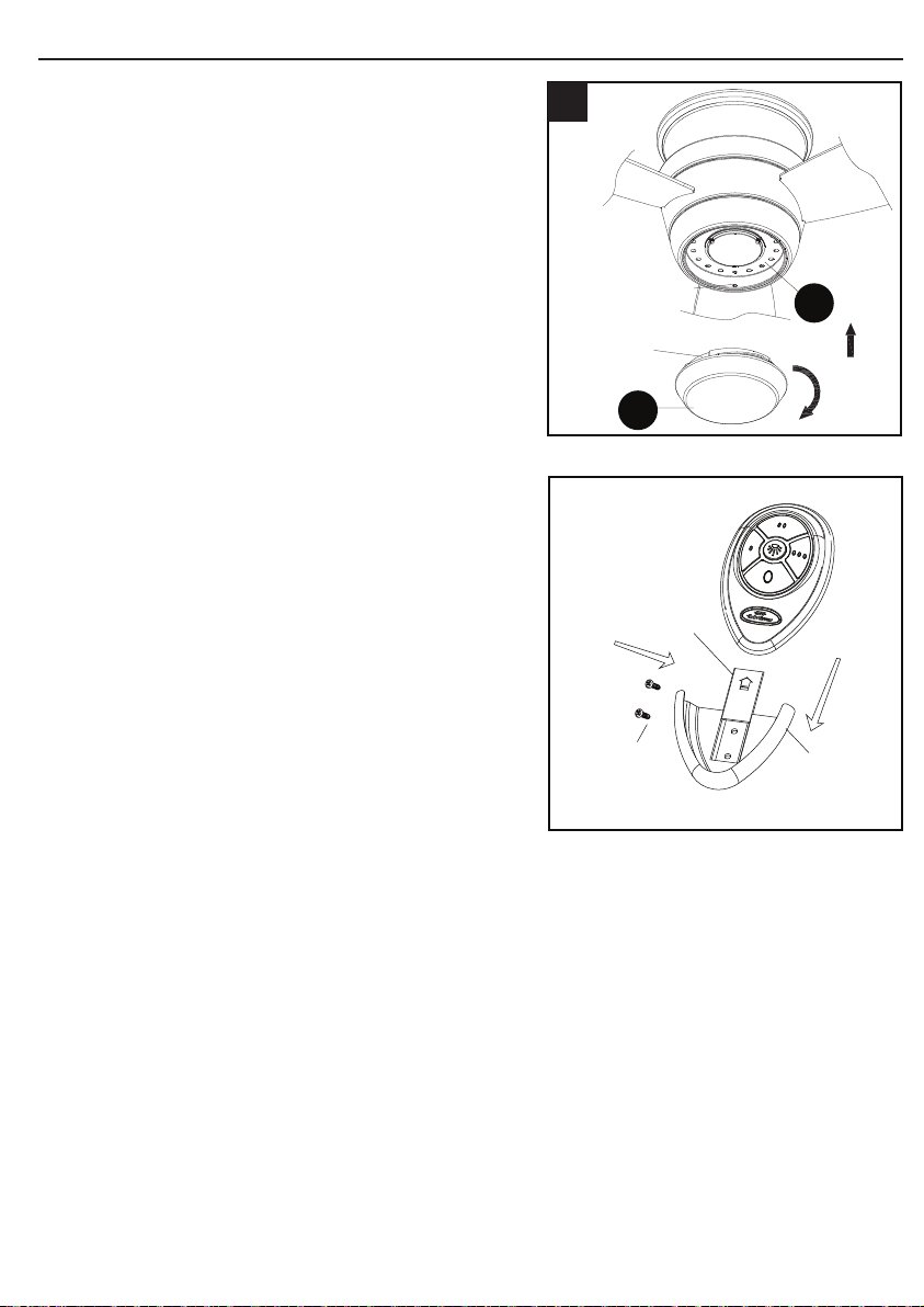
ASSEMBLY INSTRUCTIONS
OPTIONAL: If desired, the wall bracket in
remote pack (J) can be installed to house
the remote control. Remove the small plate
preassembled on the wall bracket and use the
screws in remote pack (J) to secure the wall
bracket at desired mounting location. Replace
the small plate, then rest the remote control
from remote pack (J) into wall bracket.
13. Align the three at areas on the top ange of
the glass (G) with the three raised dimples in
the light xture (F). Insert the glass (G) into
the light xture (F), then turn the glass (G)
clockwise until it stops.
Raised
dimples
Flat area
F
G
13
10
CAUTION: Avoid touching the LED with
your bare hands. Be sure the power is off
and the glass and LED are cool before
cleaning the xture.
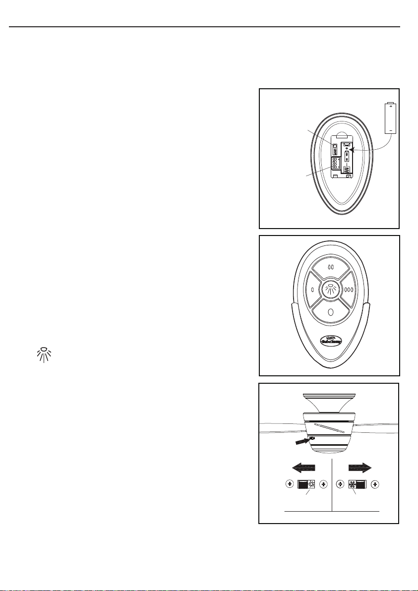
OPERATING INSTRUCTIONS
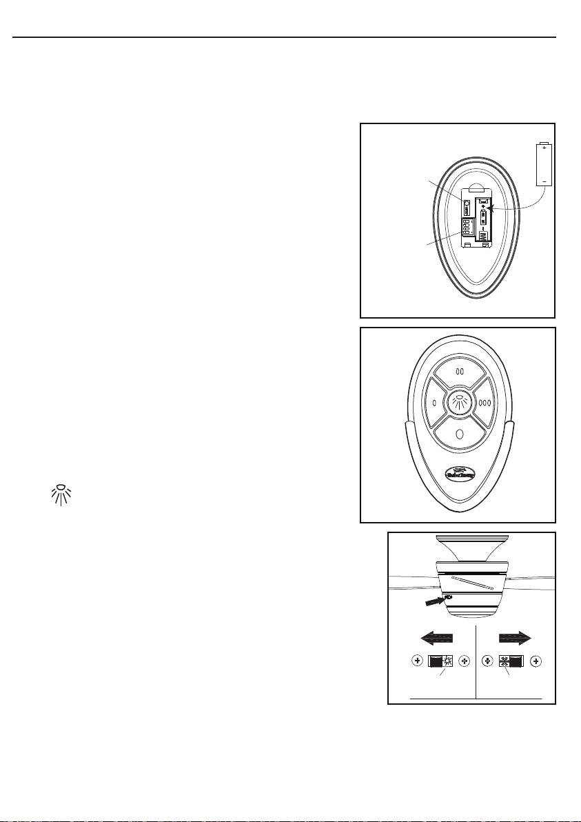
1. Install Battery/Learning Process:
Remove the battery cover from the back of the remote
found in the remote pack (J). Insert the battery from the
remote pack (J) into the remote; ensure polarity of battery
matches the polarity indicated in the battery compartment
-- positive (+) to positive (+) and negative (-) to negative (-).
Replace the battery cover.
If you need to change the dip switches in the remote control
due to a potential interference issue, slide the dip switches
to your choice of either up or down -- the factory setting
is up. Within 30 seconds of turning the fan’s power on,
press and hold the “Learn” button on the remote control
for 1 second. Once the receiver has detected the set
frequency, the light of the fan will blink twice. Replace the
battery cover. To conrm the remote control and receiver
have paired successfully press any of the fan speed control
buttons on the remote control.
2. Fan Speed Control/Dimmer:
REMOTE CONTROL:
NOTE: If you have more than one remote controlled fan installed in the same location, you may
want to change the frequency of the remote control to avoid any possible interference between
remote controls. To change the frequency of the remote control, change the dip switch settings as
described below:
Learn key
Dip switch
0 Low speed
0 0 Medium speed
0 0 0 High speed
O Turns fan off
Turns light on or off
NOTE: For the DIMMER function, press and hold the light
button. Light will dim. Release the button when light is at
desired level.
NOTE: This remote control has a memory function. The
receiver stores the fan speed and light setting when the fan is
turned off. When fan is turned on again, it starts with the most
recent settings.
3. Reverse Switch:
When the season changes
,you may want to change the
direction the fan blades spin. To switch between clockwise
and counterclockwise rotation, ip the fan reversal switch.
Sun
icon
Snowflake
icon
WARNING: Wait for fan to stop before reversing switch.
• In warmer weather, counterclockwise rotation creates a
downward airow, which cools the air. Push the switch
LEFT and see a Sun icon.
• In cooler weather, clockwise rotation creates an upward
airow, which moves hot air from the ceiling into the
room. Push the switch RIGHT and see a Snowake icon.
Small plate
Wall
bracket
Screws
11
ASSEMBLY INSTRUCTIONS
OPTIONAL: If desired, the wall bracket in
remote pack (J) can be installed to house
the remote control. Remove the small plate
preassembled on the wall bracket and use the
screws in remote pack (J) to secure the wall
bracket at desired mounting location. Replace
the small plate, then rest the remote control
from remote pack (J) into wall bracket.
13. Align the three at areas on the top ange of
the glass (G) with the three raised dimples in
the light xture (F). Insert the glass (G) into
the light xture (F), then turn the glass (G)
clockwise until it stops.
Raised
dimples
Flat area
F
G
13
10
CAUTION: Avoid touching the LED with
your bare hands. Be sure the power is off
and the glass and LED are cool before
cleaning the xture.
OPERATING INSTRUCTIONS
1. Install Battery/Learning Process:
Remove the battery cover from the back of the remote
found in the remote pack (J). Insert the battery from the
remote pack (J) into the remote; ensure polarity of battery
matches the polarity indicated in the battery compartment
-- positive (+) to positive (+) and negative (-) to negative (-).
Replace the battery cover.
If you need to change the dip switches in the remote control
due to a potential interference issue, slide the dip switches
to your choice of either up or down -- the factory setting
is up. Within 30 seconds of turning the fan’s power on,
press and hold the “Learn” button on the remote control
for 1 second. Once the receiver has detected the set
frequency, the light of the fan will blink twice. Replace the
battery cover. To conrm the remote control and receiver
have paired successfully press any of the fan speed control
buttons on the remote control.
2. Fan Speed Control/Dimmer:
REMOTE CONTROL:
NOTE: If you have more than one remote controlled fan installed in the same location, you may
want to change the frequency of the remote control to avoid any possible interference between
remote controls. To change the frequency of the remote control, change the dip switch settings as
described below:
Learn key
Dip switch
0 Low speed
0 0 Medium speed
0 0 0 High speed
O Turns fan off
Turns light on or off
NOTE: For the DIMMER function, press and hold the light
button. Light will dim. Release the button when light is at
desired level.
NOTE: This remote control has a memory function. The
receiver stores the fan speed and light setting when the fan is
turned off. When fan is turned on again, it starts with the most
recent settings.
3. Reverse Switch:
When the season changes
,you may want to change the
direction the fan blades spin. To switch between clockwise
and counterclockwise rotation, ip the fan reversal switch.
Sun
icon
Snowflake
icon
WARNING: Wait for fan to stop before reversing switch.
• In warmer weather, counterclockwise rotation creates a
downward airow, which cools the air. Push the switch
LEFT and see a Sun icon.
• In cooler weather, clockwise rotation creates an upward
airow, which moves hot air from the ceiling into the
room. Push the switch RIGHT and see a Snowake icon.
Small plate
Wall
bracket
Screws
1312
TROUBLESHOOTING
CARE AND MAINTENANCE
• IMPORTANT: Shut off main power supply before beginning any maintenance.
• Do not use water or detergents when cleaning the fan or fan blades. A dry dust cloth or
lightly dampened cloth will be suitable for most cleaning.
• At least twice a year, tighten all screws and lower canopy to check mounting bracket
screws and downrod assembly.
• Clean fan housing with only a soft brush or lint-free cloth to avoid scratching the nish.
Clean blades with a lint-free cloth. You may occasionally apply a light coat of furniture
polish to blades for added protection.
• Total xture wattage is 17.5 watts; do not attempt to replace LEDs.
• Battery replacement: Use an A23 12-volt alkaline battery for the remote control.
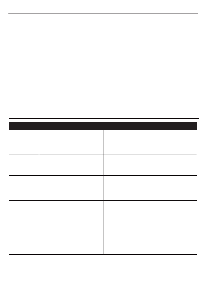
PROBLEM POSSIBLE CAUSE CORRECTIVE ACTION
Fan blades
do not move.
1. The power is off or the fuse
is blown.
1. Turn the power on or check fuse.
2. Turn power off. Loosen motor housing;
check all the connections.
Noisy
operation.
1. Blades are loose.
2. Cracked blade.
1. Tighten all blade screws.
2. Replace blades (call customer service).
Excessive
wobbling.
1. The blades are loose.
2. The fan is not securely
mounted
1. Tighten all blade screws.
2. Turn power off. Carefully loosen the canopy
and remount securely.
Remote
control
malfunction.
1. No sound after the fan power
is on.
2. No ash on transmitter LED.
3. The remote control does not
work.
1. Please check if the power supply is
connected properly and main power is on.
2. Please check if the battery is installed into
the remote control. Make sure the battery is
installed properly. One side of the battery is
positive and the other is negative.
3. Sync the remote control to the receiver
following the steps described in step 1 on
page 11. Make sure power to the fan is off
before beginning the sync process.
WARRANTY
REPLACEMENT PARTS LIST
Printed in China
For replacement parts, call our customer service department at 1-800-643-0067,
8 a.m. - 6 p.m., EST, Monday - Thursday, 8 a.m. - 5 p.m., EST, Friday.
The manufacturer warrants this fan to be free from defects in workmanship and material present at
time of shipment from the factory for lifetime limited from the date of purchase. This warranty applies
only to the original purchaser. The manufacturer agrees to correct such defect at no charge or at our
option replace the ceiling fan with a comparable or superior model.
To obtain warranty service, present a copy of your sales receipt as proof of purchase. All cost of
removal and reinstallation are the expressed responsibility of the purchaser. Any damage to the
ceiling fan by accident, misuse, or improper installation, or by afxing accessories not produced by
the manufacturer of the fan, are at the purchaser’s own responsibility. The manufacturer assumes
no responsibility whatsoever for fan installation during the lifetime limited warranty. Any service
performed by an unauthorized person will render the warranty invalid.
Due to varying climatic conditions, this warranty does not cover changes in brass nish, rusting,
pitting, tarnishing, corroding, or peeling. Brass nish fans maintain their beauty when protected from
varying weather conditions. Any glass provided with this fan is not covered by this warranty. Any
replacement of defective parts for the ceiling fan must be reported within the rst year from the date
of purchase. For the balance of the warranty, call our customer service department at 1-800-643-
0067 for return authorization and shipping instructions so that we may repair or replace the ceiling
fan. Any fan or parts returned improperly packaged is the sole responsibility of the purchaser. There
is no further expressed warranty. The manufacturer disclaims any and all implied warranties.
The duration of any implied warranty which can not be disclaimed is limited to the lifetime limited
period as specied in our warranty. The manufacturer shall not be liable for incidental, consequential
or special damages arising at or in connection with product use or performance except as may
otherwise be accorded by law. This warranty gives you specic legal rights an you also have other
rights which may vary from state to state. This warranty supersedes all prior warranties.
Note: A small amount of “wobble” is normal and should not be considered a defect.
PART DESCRIPTION PART #
Item #0807421 Item #0807422
D Blade 108001-60816C 108002-50847C
F Light Fixture 105000-0784WW
G Glass 991300-0545AQ
J Remote Pack 990319-015000
K Receiver 990319-402100
D
F
J
K
G
1312
TROUBLESHOOTING
CARE AND MAINTENANCE
• IMPORTANT: Shut off main power supply before beginning any maintenance.
• Do not use water or detergents when cleaning the fan or fan blades. A dry dust cloth or
lightly dampened cloth will be suitable for most cleaning.
• At least twice a year, tighten all screws and lower canopy to check mounting bracket
screws and downrod assembly.
• Clean fan housing with only a soft brush or lint-free cloth to avoid scratching the nish.
Clean blades with a lint-free cloth. You may occasionally apply a light coat of furniture
polish to blades for added protection.
• Total xture wattage is 17.5 watts; do not attempt to replace LEDs.
• Battery replacement: Use an A23 12-volt alkaline battery for the remote control.
PROBLEM POSSIBLE CAUSE CORRECTIVE ACTION
Fan blades
do not move.
1. The power is off or the fuse
is blown.
1. Turn the power on or check fuse.
2. Turn power off. Loosen motor housing;
check all the connections.
Noisy
operation.
1. Blades are loose.
2. Cracked blade.
1. Tighten all blade screws.
2. Replace blades (call customer service).
Excessive
wobbling.
1. The blades are loose.
2. The fan is not securely
mounted
1. Tighten all blade screws.
2. Turn power off. Carefully loosen the canopy
and remount securely.
Remote
control
malfunction.
1. No sound after the fan power
is on.
2. No ash on transmitter LED.
3. The remote control does not
work.
1. Please check if the power supply is
connected properly and main power is on.
2. Please check if the battery is installed into
the remote control. Make sure the battery is
installed properly. One side of the battery is
positive and the other is negative.
3. Sync the remote control to the receiver
following the steps described in step 1 on
page 11. Make sure power to the fan is off
before beginning the sync process.
WARRANTY
REPLACEMENT PARTS LIST
Printed in China
For replacement parts, call our customer service department at 1-800-643-0067,
8 a.m. - 6 p.m., EST, Monday - Thursday, 8 a.m. - 5 p.m., EST, Friday.
The manufacturer warrants this fan to be free from defects in workmanship and material present at
time of shipment from the factory for lifetime limited from the date of purchase. This warranty applies
only to the original purchaser. The manufacturer agrees to correct such defect at no charge or at our
option replace the ceiling fan with a comparable or superior model.
To obtain warranty service, present a copy of your sales receipt as proof of purchase. All cost of
removal and reinstallation are the expressed responsibility of the purchaser. Any damage to the
ceiling fan by accident, misuse, or improper installation, or by afxing accessories not produced by
the manufacturer of the fan, are at the purchaser’s own responsibility. The manufacturer assumes
no responsibility whatsoever for fan installation during the lifetime limited warranty. Any service
performed by an unauthorized person will render the warranty invalid.
Due to varying climatic conditions, this warranty does not cover changes in brass nish, rusting,
pitting, tarnishing, corroding, or peeling. Brass nish fans maintain their beauty when protected from
varying weather conditions. Any glass provided with this fan is not covered by this warranty. Any
replacement of defective parts for the ceiling fan must be reported within the rst year from the date
of purchase. For the balance of the warranty, call our customer service department at 1-800-643-
0067 for return authorization and shipping instructions so that we may repair or replace the ceiling
fan. Any fan or parts returned improperly packaged is the sole responsibility of the purchaser. There
is no further expressed warranty. The manufacturer disclaims any and all implied warranties.
The duration of any implied warranty which can not be disclaimed is limited to the lifetime limited
period as specied in our warranty. The manufacturer shall not be liable for incidental, consequential
or special damages arising at or in connection with product use or performance except as may
otherwise be accorded by law. This warranty gives you specic legal rights an you also have other
rights which may vary from state to state. This warranty supersedes all prior warranties.
Note: A small amount of “wobble” is normal and should not be considered a defect.
PART DESCRIPTION PART #
Item #0807421 Item #0807422
D Blade 108001-60816C 108002-50847C
F Light Fixture 105000-0784WW
G Glass 991300-0545AQ
J Remote Pack 990319-015000
K Receiver 990319-402100
D
F
J
K
G

VENTILADOR DE TECHO
MAZON
ARTÍCULO #0807421, 0807422
MODELO #00728, 00729
Número de serie Fecha de compra
Harbor Breeze® es una marca registrada de LF,
LLC. Todos los derechos reservados.
¿Preguntas, problemas, piezas faltantes? Antes de volver a la tienda, llame a nuestro
Departamento de Servicio al Cliente al 1-800-643-0067, de lunes a jueves, de 8 a. m. a
6 p. m., hora estándar del Este, y los viernes de 8 a. m. a 5 p. m., hora estándar del Este.
ADJUNTE SU RECIBO AQUÍ
UL #44-MZ

ÍNDICE
Contenido del paquete................................................................................................17
Aditamentos...............................................................................................................18
Preparación................................................................................................................18
Información de seguridad............................................................................................19
Instrucciones de ensamblaje......................................................................................20
Instrucciones de funcionamiento.................................................................................25
Cuidado y mantenimiento............................................................................................26
Solución de problemas................................................................................................26
Garantía.....................................................................................................................27
Lista de piezas de repuesto........................................................................................27
CONTENIDO DEL PAQUETE
1615
A
B
H
C
D
E
F
G
I
J
PIEZA DESCRIPCIÓN CANTIDAD
A Placa de montaje 1
B Motor del ventilador 1
C Anillo de reborde 1
D Aspa 3
E Placa de iluminación 1
F Ensamble de iluminación 1
G
Vidrio
1
H Placa de la carcasa del interruptor
(preensamblado en el motor del ventilador (B))
1
I Lengüeta estabilizadora de goma para transporte
(preensamblada en el motor del ventilador (B))
3
J Paquete remoto 1

ADITAMENTOS
INFORMACIÓN DE SEGURIDAD
LEA Y GUARDE ESTAS INSTRUCCIONES
Lea y comprenda completamente este manual antes de intentar ensamblar, usar o instalar el producto.
• Cuandouseunacajadesalidaexistente,asegúresedequelacajaestésujetadeformaseguraalaestructuradeledicioy
que pueda soportar el peso completo del ventilador para evitar potenciales lesiones graves o la muerte.
• Todo el cableado debe cumplir el Código Eléctrico Nacional “ANSI/NFPA 70” y los códigos eléctricos locales. La instalación
eléctricadebeserrealizadaporunelectricistacalicadoyautorizado.
• Después de realizar las conexiones del cableado, estos deben separarse de modo que el conductor de puesta a tierra y el
conductor de puesta a tierra del equipo queden hacia un lado de la caja de salida y el conductor sin puesta a tierra hacia
el otro lado.
• Sedebenrevisartodoslostornillosdejaciónyvolveraajustarseantesydurantelainstalación.
• Después de hacer los empalmes, se deben girar hacia arriba y empujar con cuidado hasta introducirlos en la caja de salida.
• Desconecte el circuito de suministro de electricidad del ventilador antes de instalar el kit.
• Losdiagramaseléctricostienenunanalidaddereferenciaúnicamente.
• El peso neto de este ventilador, incluido el kit de iluminación, es: 7,1 kg.
• PELIGRO DE DESCARGA ELÉCTRICA: no instale este ventilador con un control de pared de velocidad variable o un
regulador de intensidad montado en la pared. Esto dañará de manera permanente el receptor del control remoto del
ventilador y ocasionará fallas en las funciones del ventilador.
ADVERTENCIA
• RIESGO DE DESCARGA ELÉCTRICA: para reducir el riesgo de descargas eléctricas, este ventilador debe instalarse
con un interruptor de control de aislamiento de pared.
• RIESGO DE DESCARGA ELÉCTRICA: para reducir el riesgo de descargas eléctricas, asegúrese de cortar la
electricidad en la caja del interruptor de circuito o en la caja de fusibles antes de comenzar la instalación.
• RIESGO DE LESIONES PERSONALES: para reducir el riesgo de lesiones a personas, instale el ventilador de forma
que las aspas estén a 2,1 m (7 pies) sobre el piso.
PRECAUCIÓN
• RIESGO DE LESIONES PERSONALES: para reducir el riesgo de lesiones personales, no doble las abrazaderas de
las aspas al instalar las abrazaderas, equilibrar las aspas o limpiar el ventilador. NO coloque objetos extraños entre
las aspas en movimiento del ventilador.
1817
PREPARACIÓN
Antes de comenzar a ensamblar el producto, asegúrese de tener todas las piezas.
Compare las piezas con la lista del contenido del paquete y la lista del contenido de
aditamentos. Si faltan piezas o alguna está dañada, no intente ensamblar el producto.
Tiempo estimado de ensamblaje: 45 minutos
Herramientas necesarias para el ensamblaje (no se incluyen): destornillador Phillips,
escalera de tijera, cinta aislante, pinzas, pinzas cortacables, pinzas pelacables.
Herramientas útiles (no se incluyen): probador de circuito eléctrico
Este equipo ha sido probado y se ha vericado quecumple con los límites para un dispositivo digital clase B, conforme a
la sección 15 de las reglas de la FCC. Estos límites están diseñados para proporcionar protección razonable contra
interferencias perjudiciales en una instalación residencial. Este equipo genera, utiliza y puede irradiar energía de
radiofrecuencia y, si no se instala y usa de acuerdo con las instrucciones, puede causar interferencia perjudicial a
las comunicaciones de radio. Sin embargo, no se garantiza que no se producirán interferencias en una instalación
en especial. Si este equipo genera una interferencia perjudicial para la recepción de radio o televisión, que se puede
determinar apagando y encendiendo el equipo, se recomienda al usuario que intente corregir la interferencia con una
o más de las siguientes medidas:
• Reoriente o reubique la antena de recepción.
• Aumente la separación entre el equipo y el receptor.
• Conecte el equipo a un tomacorriente de un circuito distinto al que usa el receptor.
• Solicite ayuda al distribuidor o a un técnico con experiencia en radio/TV.
PRECAUCIÓN: cualquier cambio o modicación que no esté expresamente aprobado por el cesionario de este dispositivo
podría anular la autorización del usuario para utilizar el equipo.
Este dispositivo cumple con la sección 15 de las reglas de la FCC. El funcionamiento está sujeto a las siguientes dos condiciones:
(1) Este dispositivo no debe causar interferencia perjudicial, y (2) deberá aceptar cualquier interferencia recibida, incluida la
interferencia que pudiese causar la operación no deseada.
• RIESGO DE LESIONES PERSONALES, INCENDIO O DESCARGA ELÉCTRICA: para reducir el riesgo de incendio,
descargas eléctricas o lesiones personales, instale el ventilador en una caja de salida que esté marcada como “ACCEPTABLE
FOR FAN SUPPORT OF 35.1 LBS OR LESS” (Apta para sostener ventiladores de 15,92 kg. (35,1 lb) o menos) y utilice
los tornillos de montaje incluidos con la caja de salida. La mayoría de las cajas de salida que se usan comúnmente para
sostener lámparas no son aptas para sostener un ventilador y puede ser necesario reemplazarlas. Si tiene dudas, consulte
conunelectricistacalicadoyautorizado.
AA
BB
Conector de cables
Cant. 3 + 1 adicional
Tornillo para aspas
Cant. 9 + 1 adicional
ON
Interruptor de
encendido/apagado
NO USAR control de pared
de velocidad variable
NO USAR regulador
de intensidad
INSTRUCCIONES DE ENSAMBLAJE
1. Fije la placa de montaje (A) a la caja de
salida (no se incluye) con dos tornillos (no se
incluyen).Aprietermementelosdostornillos
de la caja de salida. Jale los cables negro,
blanco y de puesta a tierra hacia fuera de la
cajadesalidaypáselosporeloriciodela
placa de montaje (A).
2. Coloque el anillo de reborde (C) sobre
la base y deposítelo sobre el motor del
ventilador (B).
3. Aojedostornillospreensamblados,unofrente
a otro, en la placa de montaje (A). Retire los
dos tornillos preensamblados que quedan y
guárdelos. Cuelgue el motor del ventilador (B)
en el gancho de la placa de montaje (A) usando
unodelosoriciossinranuraenlabase.
2019
A
Caja de
salida
Tornillo
1
Puesta a tierra/
Verde
Blanco
Negro
Verde/
Puesta a
tierra
Negro
Negro
Blanco
Verde
Caja de
salida
Receptor
Blanco
Circuito de
suministro
4
AA
5
B
A
Tornillo
6
B
C
Base
2
A
B
Base
Tornillo
Gancho
3
INSTRUCCIONES DE ENSAMBLAJE
6. Alinee las ranuras con forma de cerradura
del motor del ventilador (B) con las cabezas
sobresalientes de los tornillos en la placa de
montaje (A). Levante el motor del ventilador (B)
hasta la placa de montaje (A) y asegúrese de
no romper ninguna conexión del cableado. Gire
el motor del ventilador (B) en dirección de las
manecillas del reloj hasta que las cabezas de
los tornillos calcen por completo en las ranuras
con forma de cerradura. Inserte los tornillos
que retiró con anterioridad (paso 3, página 19)
yaprietermementetodoslostornillos.
IMPORTANTE: NO use este ventilador con
un regulador de intensidad o con un control
de pared de velocidad variable, ya que esto
dañará el ventilador.
4. Conecte el cable NEGRO del ventilador con
el cable NEGRO del techo. Conecte el cable
BLANCO del ventilador con el cable BLANCO
del techo. Conecte todos los cables de PUESTA
A TIERRA (VERDES) del ventilador con el
cable VERDE o conductor DESNUDO del
techo. La conexión de los cables VERDES o de
PUESTA A TIERRA sirve para recibir la señal
del control remoto.
NOTA: El cable NEGRO es el que proporciona
alimentación al ventilador y al kit de iluminación.
El cable BLANCO es el mismo para el ventilador
y para el kit de iluminación. El cable VERDE es
el cable de puesta a tierra. Si los cables de la
casa no tienen los colores que se mencionaron
anteriormente, deténgase de inmediato y consulte
con un electricista profesional para determinar el
cableado correcto.
5. Tuerza los extremos de los cables y enrosque
los conectores de cables (AA) en dirección de
las manecillas del reloj. Una los conectores de
cables (AA) y los cables con cinta aislante (no
se incluye).
Aditamentos utilizados
x 3
Conector de cables
AA
ON
Interruptor de
encendido/
apagado
NO USAR
control de pared
de velocidad
variable
NO USAR
regulador
de intensidad

INSTRUCCIONES DE ENSAMBLAJE
1. Fije la placa de montaje (A) a la caja de
salida (no se incluye) con dos tornillos (no se
incluyen).Aprietermementelosdostornillos
de la caja de salida. Jale los cables negro,
blanco y de puesta a tierra hacia fuera de la
cajadesalidaypáselosporeloriciodela
placa de montaje (A).
2. Coloque el anillo de reborde (C) sobre
la base y deposítelo sobre el motor del
ventilador (B).
3. Aojedostornillospreensamblados,unofrente
a otro, en la placa de montaje (A). Retire los
dos tornillos preensamblados que quedan y
guárdelos. Cuelgue el motor del ventilador (B)
en el gancho de la placa de montaje (A) usando
unodelosoriciossinranuraenlabase.
2019
A
Caja de
salida
Tornillo
1
Puesta a tierra/
Verde
Blanco
Negro
Verde/
Puesta a
tierra
Negro
Negro
Blanco
Verde
Caja de
salida
Receptor
Blanco
Circuito de
suministro
4
AA
5
B
A
Tornillo
6
B
C
Base
2
A
B
Base
Tornillo
Gancho
3
INSTRUCCIONES DE ENSAMBLAJE
6. Alinee las ranuras con forma de cerradura
del motor del ventilador (B) con las cabezas
sobresalientes de los tornillos en la placa de
montaje (A). Levante el motor del ventilador (B)
hasta la placa de montaje (A) y asegúrese de
no romper ninguna conexión del cableado. Gire
el motor del ventilador (B) en dirección de las
manecillas del reloj hasta que las cabezas de
los tornillos calcen por completo en las ranuras
con forma de cerradura. Inserte los tornillos
que retiró con anterioridad (paso 3, página 19)
yaprietermementetodoslostornillos.
IMPORTANTE: NO use este ventilador con
un regulador de intensidad o con un control
de pared de velocidad variable, ya que esto
dañará el ventilador.
4. Conecte el cable NEGRO del ventilador con
el cable NEGRO del techo. Conecte el cable
BLANCO del ventilador con el cable BLANCO
del techo. Conecte todos los cables de PUESTA
A TIERRA (VERDES) del ventilador con el
cable VERDE o conductor DESNUDO del
techo. La conexión de los cables VERDES o de
PUESTA A TIERRA sirve para recibir la señal
del control remoto.
NOTA: El cable NEGRO es el que proporciona
alimentación al ventilador y al kit de iluminación.
El cable BLANCO es el mismo para el ventilador
y para el kit de iluminación. El cable VERDE es
el cable de puesta a tierra. Si los cables de la
casa no tienen los colores que se mencionaron
anteriormente, deténgase de inmediato y consulte
con un electricista profesional para determinar el
cableado correcto.
5. Tuerza los extremos de los cables y enrosque
los conectores de cables (AA) en dirección de
las manecillas del reloj. Una los conectores de
cables (AA) y los cables con cinta aislante (no
se incluye).
Aditamentos utilizados
x 3
Conector de cables
AA
ON
Interruptor de
encendido/
apagado
NO USAR
control de pared
de velocidad
variable
NO USAR
regulador
de intensidad
2221
INSTRUCCIONES DE ENSAMBLAJE
7. Alinee las muescas en la base del motor del
ventilador (B) con las áreas elevadas en el
interior del anillo de reborde (C). Instale el
anillo de reborde (C) en la base.
8. Retire y deseche las lengüetas estabilizadoras
de goma para transporte (I) del motor del
ventilador (B). Inserte un aspa (D) en la ranura
del motor del ventilador (B). Fije el aspa (D) con
los tres tornillos para las aspas (BB). Repita el
procedimiento para las aspas (D) y los tornillos
de las aspas (BB) restantes.
9. Aojedostornillosdelaplacadela
carcasa del interruptor (H). Retire y
conserve el tornillo que queda.
B
C
Base
Muesca
Area
elevada
7
D
BB
I
B
Ranura
8
H
Tornillo
9
INSTRUCCIONES DE ENSAMBLAJE
10. Conecte el enchufe de 9 clavijas que sale
de la parte inferior del motor del ventilador
(B) al enchufe de 9 clavijas de la placa
de iluminación (E). Asegúrese de que los
enchufes encajen juntos completamente. Fije
la placa de iluminación (E) a la placa de la
carcasadelinterruptor(H).Alineelosoricios
principales y luego gire para bloquear. Vuelva
a instalar el tornillo que retiró con anterioridad
(paso9,página21)yaprietermementetodos
los tornillos.
11. Aojedostornillospreensambladosenla
placa de iluminación (E). Retire y guarde el
tornillo preensamblado restante de la placa
de iluminación (E).
12. Conecte el cable BLANCO de la placa de
iluminación (E) con el cable BLANCO de
la lámpara (F). Conecte el cable AZUL de
la placa de iluminación (E) con el cable
AZUL de la lámpara (F). Alinee las ranuras
con forma de cerradura con la lámpara y
con la placa de iluminación (E) y gire para
bloquear. Vuelva a colocar el tornillo que
retiró anteriormente (paso 11, página 22) y
aprietermementetodoslostornillos.
H
B
E
Agujeros de
las cerraduras
Tornillo
Enchufe
hembra
Enchufe
macho
10
Tornillo
E
11
Tornillo
E
F
Blanco
Azul
12
Aditamentos utilizados
Tornillo de aspa x 9
BB
24
INSTRUCCIONES DE ENSAMBLAJE
14. OPCIONAL: Si lo desea, puede instalar la
abrazadera de pared del paquete remoto (J)
para colocar el control remoto. Retire la placa
pequeña preensamblada en la abrazadera de
pared y use los tornillos del paquete remoto
(J) para asegurar la abrazadera de pared en
la ubicación de montaje deseado. Vuelva a
colocar la placa pequeña y luego coloque el
resto del control remoto del paquete remoto
(J) en la abrazadera de pared.
13. Alinee las tres áreas planas de la brida supe-
rior del vidrio (G) con las tres protuberancias
en la lámpara (F). Coloque el vidrio (G) en la
lámpara (F) y gire el vidrio (G) en dirección de
las manecillas del reloj hasta que se detenga.
Protuberancias
Area plana
F
G
13
23
PRECAUCIÓN: evite tocar la bombilla LED
con las manos descubiertas. Asegúrese de
que la alimentación esté desconectada y de
que el vidrio y la bombilla LED estén fríos
antes de limpiar el ensamble.
INSTRUCCIONES DE FUNCIONAMIENTO
1. Instalación de la batería/Proceso de aprendizaje:
Retire la cubierta de la batería de la parte posterior del control
remoto que se encuentra en el paquete remoto (J). Inserte la batería
del paquete remoto (J) en el control remoto; y asegúrese de que la
polaridad de la batería coincida con la polaridad que se indica en el
compartimiento de la batería: positivo (+) con positivo (+) y negativo
(-) con negativo (-). Coloque de nuevo la cubierta de la batería.
Si necesita cambiar los interruptores magnéticos en el control
remoto debido a un posible problema de interferencia, deslice
los interruptores magnéticos a su elección hacia arriba
ohaciaabajo(laconguracióndefábricaeshaciaarriba).Dentrode
los 30 segundos luego de haber encendido la alimentación eléctrica
del ventilador, mantenga presionado el botón “Learn” (Aprender) en
el control remoto durante 1 segundo. Una vez que el receptor detecta
la frecuencia establecida, la luz descendente del ventilador titilará dos
veces. Coloque de nuevo la cubierta de la batería. Para conrmar
que el control remoto y el receptor se acoplaron de manera correcta,
presione cualquier botón del control de velocidad del ventilador en el
control remoto.
2. Control de velocidad del ventilador/Regulador:
CONTROL REMOTO:
NOTA: Si tiene más de un ventilador operado por control remoto instalado en la misma ubicación, se recomienda
cambiar la frecuencia del control remoto para evitar posibles interferencias entre los controles remotos. Para
cambiarlafrecuenciadelcontrolremoto,cambielaconguracióndelinterruptormagnéticocomosedescribe abajo.
Tecla “Learn”
(Aprender)
Interruptor
magnético
0 Velocidad baja
0 0 Velocidad media
0 0 0 Velocidad alta
O Apaga el ventilador
Enciende o apaga la luz
NOTA: Mantenga presionado el botón de la luz para regular la
intensidad. La intensidad de la luz disminuirá. Cuando la intensidad de
la luz alcance el nivel deseado, suelte el botón de la luz.
NOTA: Este control remoto tiene función de memoria.
El receptor registra la velocidad del ventilador y la intensidad de la
luz cuando se apaga el ventilador. Cuando se vuelve a encender el
ventilador,arrancaráconlaúltimaconguraciónestablecida.
3. Interruptor deslizante para seleccionar estaciones:
Cuando cambie la estación, quizás quiera cambiar la dirección de giro de
las aspas del ventilador. Para alternar entre la dirección de las manecillas
del reloj y la dirección contraria, gire el interruptor deslizante para
seleccionar estaciones.
icono del
sol
icono de copo
de niveve
ADVERTENCIA: espere a que el ventilador se detenga antes de
invertir el interruptor.
• En climas más cálidos, la rotación en dirección contraria a las manecillas del relojcreaunujodeaire
descendente que enfría el aire. Presione el interruptor hacia la IZQUIERDA y verá el ícono de un sol.
• Enclimasmásfríos,larotaciónendireccióndelasmanecillasdelrelojcreaunujodeaireascendente,
que mueve el aire caliente desde el techo hacia la parte central de la habitación. Presione el interruptor
hacia la DERECHA y verá el ícono de un copo de nieve.
Placa pequeña
Atrazadera
de pared
Tornillos
2625
SOLUCIÓN DE PROBLEMAS
CUIDADO Y MANTENIMIENTO
• IMPORTANTE: antes de realizar cualquier trabajo de mantenimiento, desconecte el suministro
de electricidad principal.
• NO use agua ni detergentes para limpiar el ventilador o las aspas. Se recomienda utilizar un
paño suave y seco o un paño levemente humedecido para limpiar el producto.
• Limpie la carcasa del ventilador solo con un cepillo de cerdas suaves o con un paño sin pelusas
para evitar que se raye el acabado. Limpie las aspas con un paño sin pelusas. De vez en cuando
puedeaplicarunanacapadeceraparamueblesenlasaspasparadarlesmásprotección.
• Almenosdosvecesalaño,aprietetodoslostornillosybajelabaseparavericarlostornillosdel
soporte de montaje y el ensamble de la varilla.
• Reemplazo de la batería: para el control remoto, utilice una batería alcalina A23 de 12 voltios.
• El vataje total de la lámpara es de 17.5 vatios; no intente reemplazar las bombillas LED.
GARANTÍA
LISTA DE PIEZAS DE REPUESTO
Impreso en China
Para obtener piezas de repuesto, llame a nuestro Departamento de Servicio al Cliente
al 1-800-643-0067 de lunes a jueves, de 8 a. m. a 6 p. m., hora estándar del Este, y los
viernes de 8 a. m. a 5 p. m., hora estándar del Este.
El fabricante garantiza que este ventilador no presenta defectos de fabricación ni en los materiales presentes
en el momento del transporte desde la fábrica, durante un período limitado de por vida a partir de la fecha de
compra. Esta garantía es válida solo para el comprador original. El fabricante acepta reparar dichos defectos sin
cargo o, según nuestro criterio, reemplazar el ventilador de techo por un modelo comparable o superior.
Para obtener el servicio de garantía, presente una copia del recibo de venta como comprobante de la compra.
Todos los costos de extracción y reinstalación son responsabilidad explícita del comprador. Los daños en el
ventilador de techo producidos por accidentes, uso indebido o instalación incorrecta, o a causa de la colocación
de accesorios de jación que no son del fabricante del ventilador, serán responsabilidad del comprador. El
fabricante no asume ningún tipo de responsabilidad por la instalación del ventilador durante la garantía limitada
de por vida. Cualquier servicio realizado por una persona no autorizada invalidará la garantía.
Debido a las cambiantes condiciones climáticas, esta garantía no cubre cambios en el acabado de latón, óxido,
picaduras, deslustre, corrosión o descascarado. Los ventiladores con acabado de latón mantienen su belleza
cuando se los protege de las condiciones climáticas cambiantes. La garantía no cubre los elementos de vidrio
incluidos con este ventilador. Cualquier reemplazo de piezas defectuosas para el ventilador de techo debe
informarse dentro del primer año a partir de la fecha de compra. Para conocer el saldo de la garantía, llame a
nuestro Departamento de Servicio al Cliente al 1-800-643-0067 para obtener la autorización para la devolución
y las instrucciones de envío, de modo que podamos reparar o reemplazar el ventilador de techo. Cualquier
ventilador o pieza devueltos con un embalaje incorrecto son responsabilidad única del comprador. No existe otro
tipo de garantía explícita. El fabricante rechaza cualquiera y todas las garantías implícitas.
La duración de cualquier garantía implícita que no pueda rechazarse se limita al período limitado de por vida
especicado en nuestra garantía. El fabricante no será responsable por daños incidentales, resultantes o
especiales que surjan en relación con el uso o el funcionamiento del producto, excepto que la ley indique lo
contrario.Estagarantíaleotorgaderechoslegalesespecícos,peropodríatenertambiénotrosderechosque
podrían variar según el estado. Esta garantía sustituye cualquier garantía previa.
NOTA: una pequeña cantidad de “tambaleo” es normal y no se debe considerar como un defecto.
PIEZA DESCRIPCIÓN PIEZA #
Artículo #0807421 Artículo #0807422
D Aspa 108001-60816C 108002-50847C
F Ensamble de iluminación 105000-0784WW
G Vidrio 991300-0545AQ
J Paquete remoto 990319-015000
K Receptor 990319-402100
D
F
J
K
G
PROBLEMA CAUSA POSIBLE ACCIÓN CORRECTIVA
Las aspas del
ventilador no se
mueven.
1. No hay suministro de
electricidad o hay un
fusible quemado.
1. Conecte la alimentación o revise el
fusible.
2. Desconectelaalimentación.Aojela
carcasa del motor
y revise todas las conexiones.
El funcionamiento
es ruidoso.
1. Lasaspasestánojas.
2. Hay un aspa partida.
1. Apriete todos los tornillos de las aspas.
2. Reemplace las aspas (llame al Servicio al
Cliente).
Hay un tambaleo
excesivo.
1. Lasaspasestánojas.
2. El ventilador no está bien
instalado.
1. Apriete todos los tornillos de las aspas.
2. Desconectelaalimentación.Aojela
base con cuidado
y vuelva a montarla.
Falla en el control
remoto.
1. No se escucha ningún
sonido cuando se
enciende el ventilador.
2. No hay destellos en el
transmisor LED.
3. El control remoto no
funciona.
1. Veriquequeelsuministrodeelectricidad
esté conectado correctamente y que
la alimentación eléctrica principal esté
encendida.
2. Veriquequelabateríaestéinstalada
en el control remoto. Asegúrese de que
la batería esté instalada correctamente.
Un lado de la batería es positivo y el otro
negativo.
3. Sincronice el control remoto con el
receptor de acuerdo al paso 1 de
la página 24. Asegúrese de que la
alimentación del ventilador esté apagada
antes de comenzar con el proceso de
sincronización.
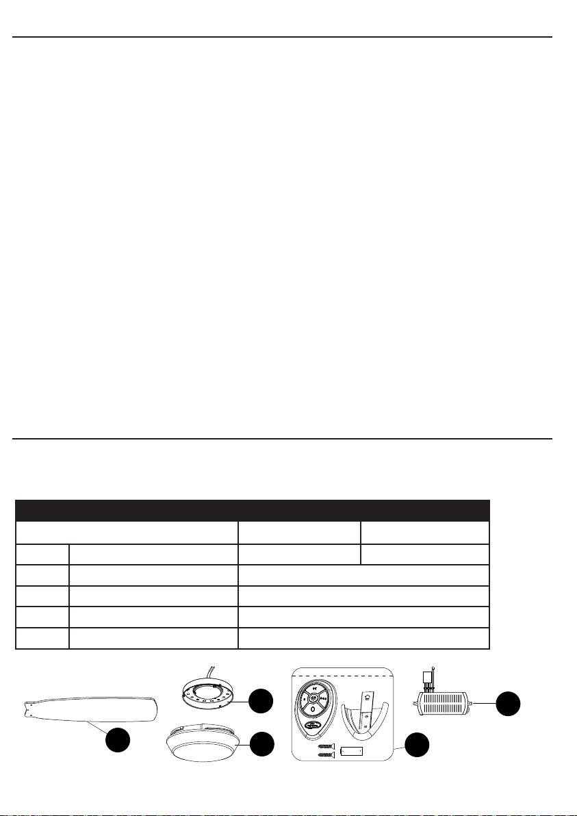