Owner's Guide Ceiling Fan
PACKAGE CONTENTS
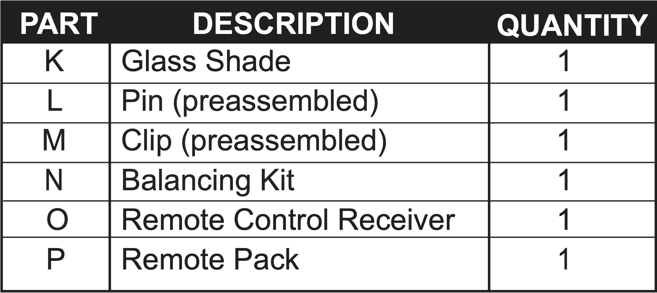
IMPORTANT REMINDER: You must use the parts provided with this fan for proper installation and safety.
HARDWARE CONTENTS (shown actual size)
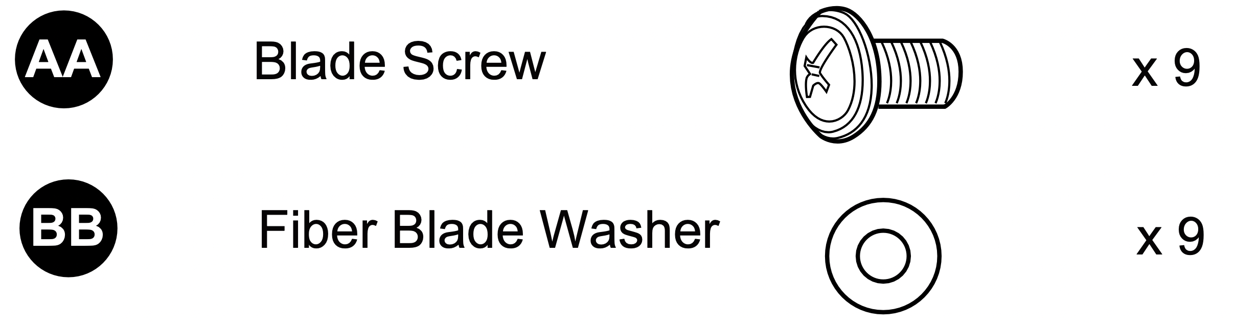
Blade Screw
Qty. 9 + 1 extra
Fiber Blade Washer
Qty. 9 + 1 extra
Wire Connector
Qty. 4
INSTALLATION
INITIAL INSTALLATION
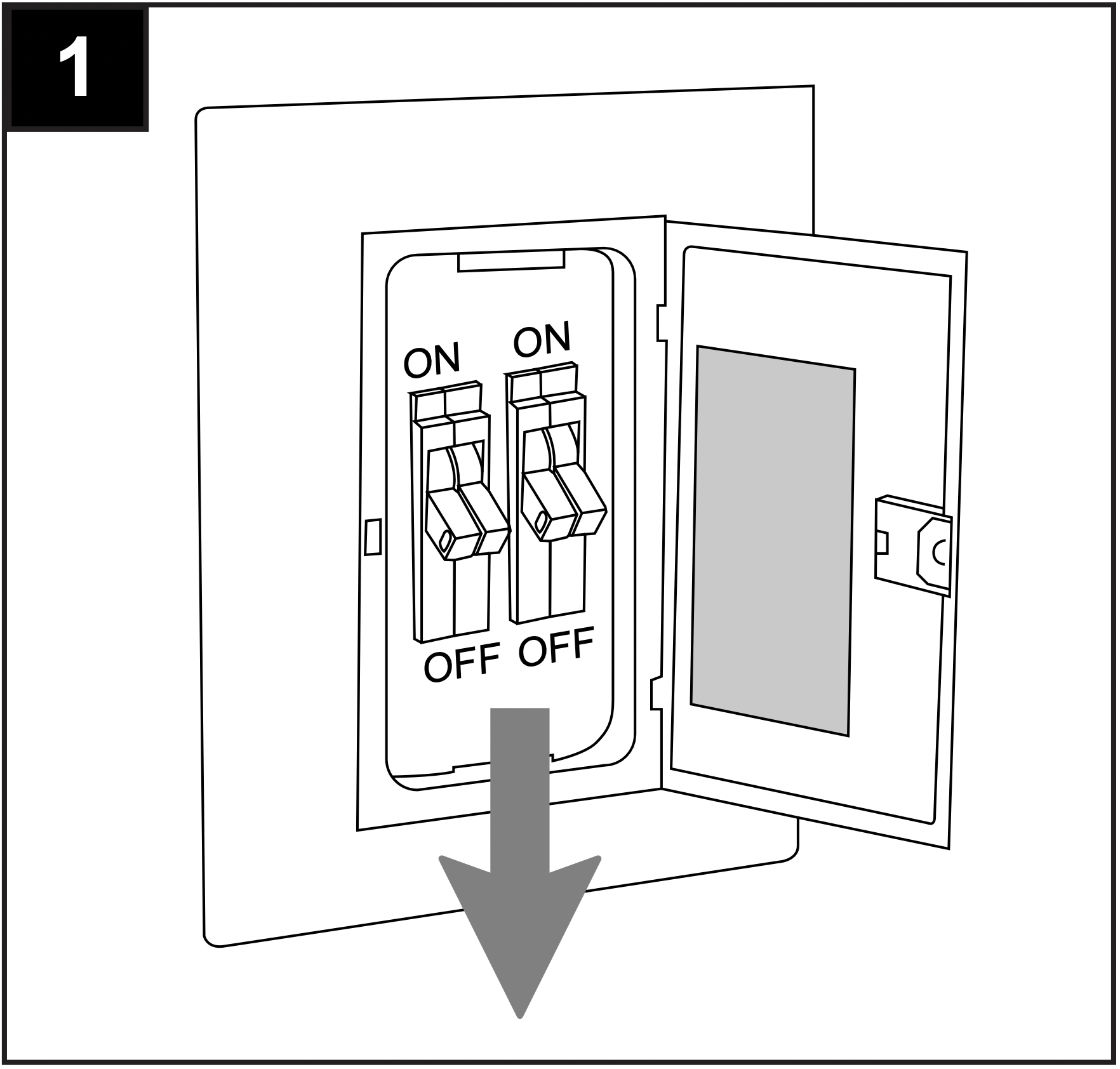
1. Turn off circuit breakers and wall switch to the fan supply line leads.
DANGER: Failure to disconnect power supply prior to installation may result in serious injury or death.
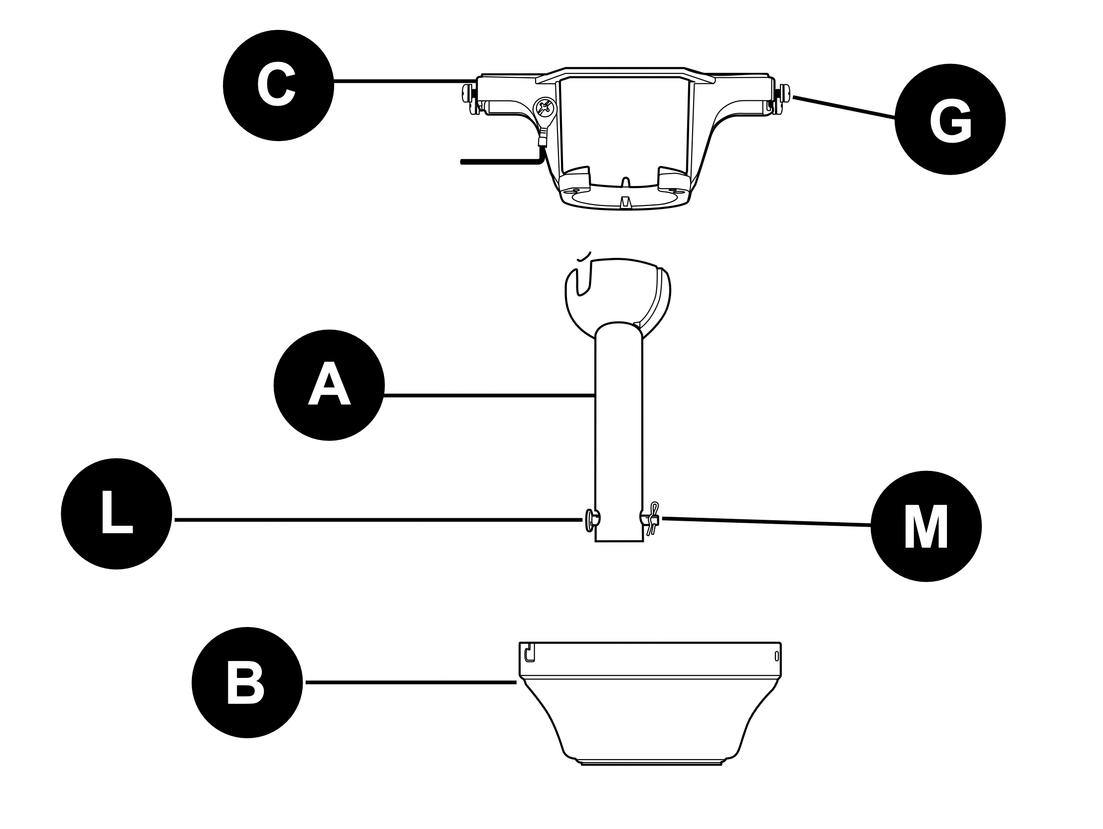
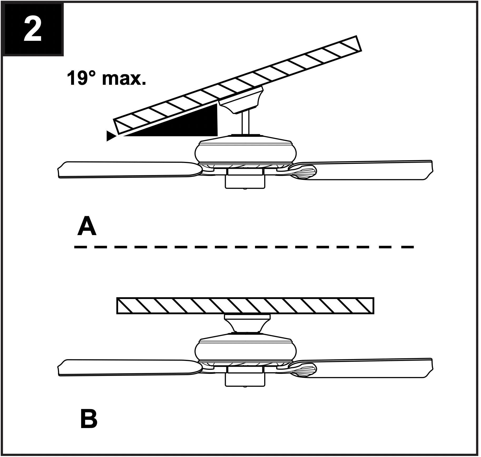
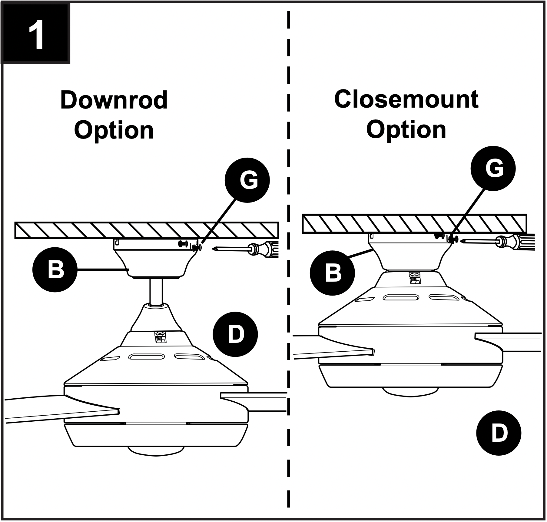
2. Determine mounting method to use.
A. Downrod mount (standard or angled ceiling)
B. Closemount (standard ceiling only)
IMPORTANT: If using the angle mount, check to make sure the ceiling angle is not steeper than 19°.
*Helpful Hint: Downrod-style mounting is best suited for ceilings 8 ft. or higher. For taller ceilings you may want to use a longer downrod (not included). Angle-style mounting is best suited for angled or vaulted ceilings. A longer downrod is sometimes necessary to ensure proper blade clearance. Closemount mounting is more suitable for ceilings lower than 8 ft. high.
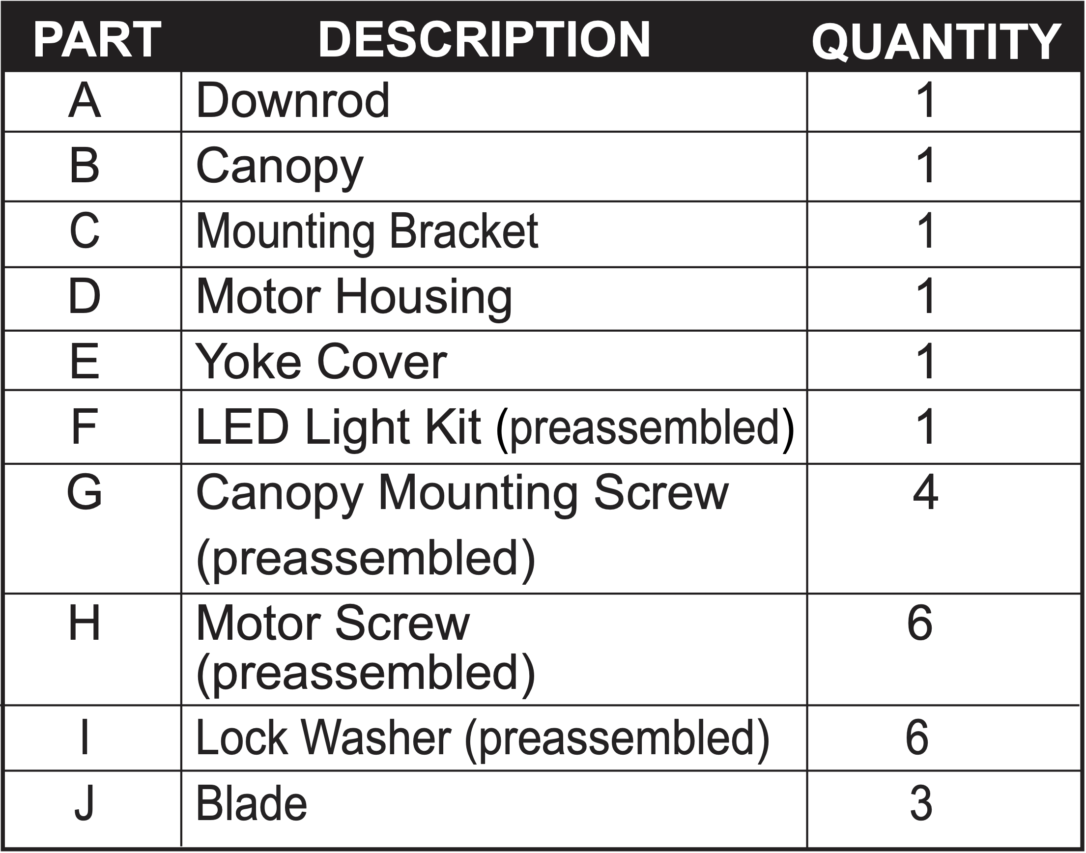
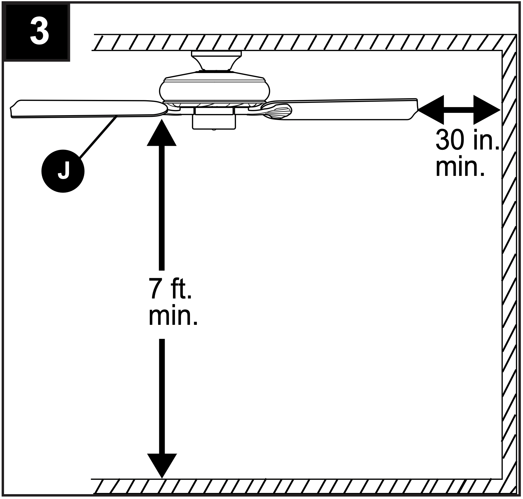
3. Check to make sure blades (J) will be at least 30 in. from any obstruction and at least 7 ft. above the floor.
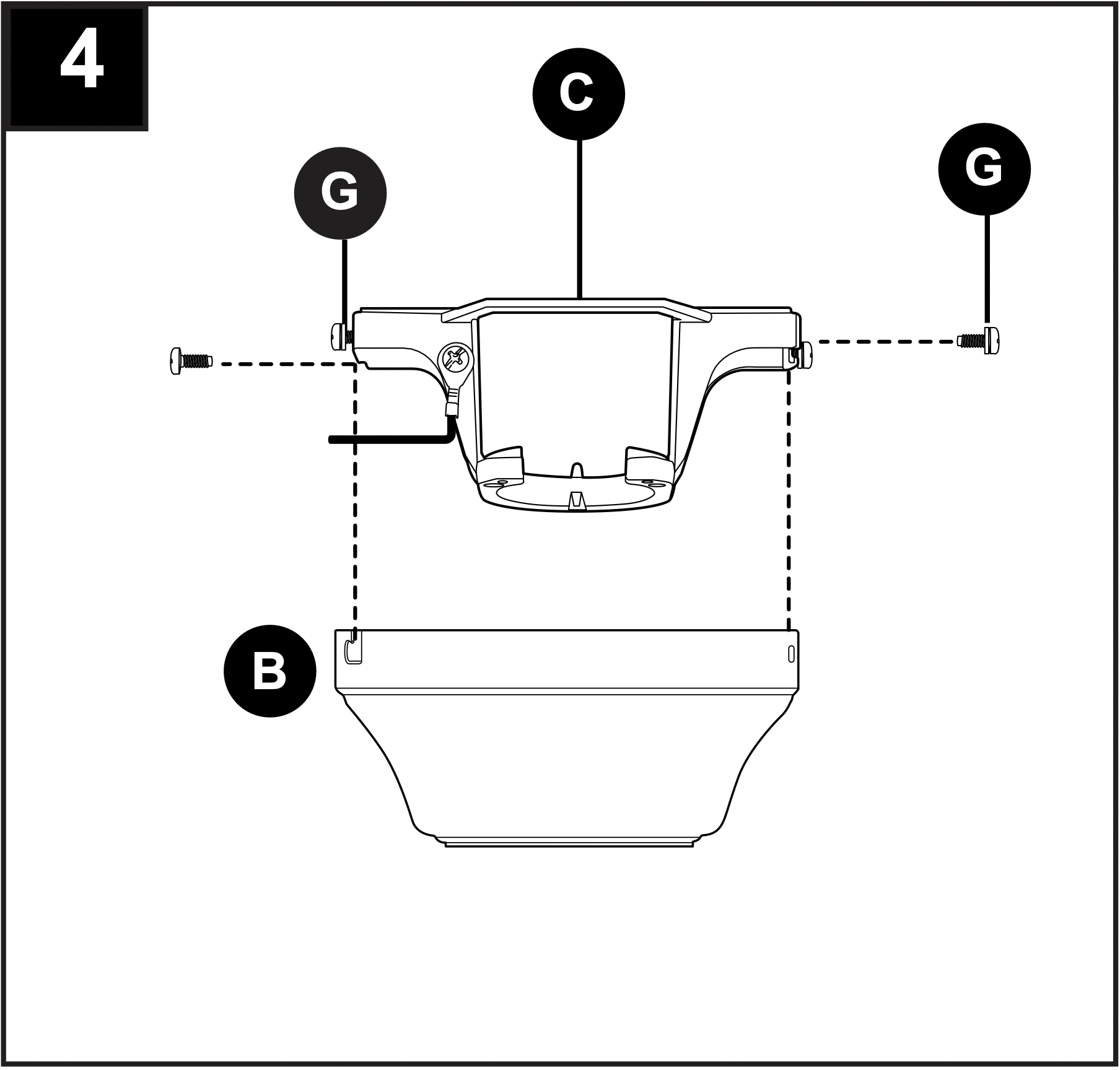
4. Temporarily raise canopy (B) to mounting bracket (C) and determine which 2 canopy mounting screws (G) align with slotted holes in canopy (B). Partially loosen these 2 canopy mounting screws (G) and remove the other two; save for later use.
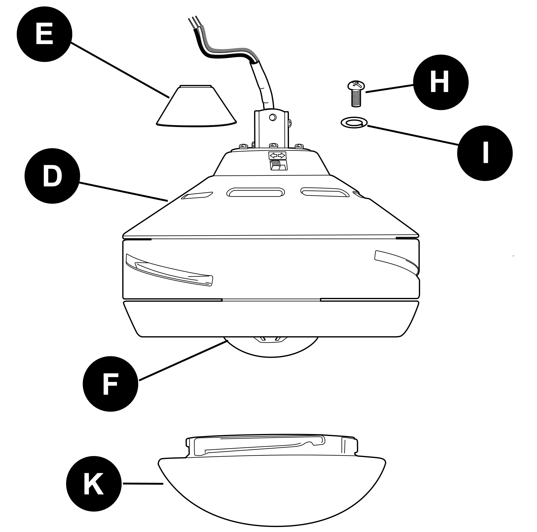
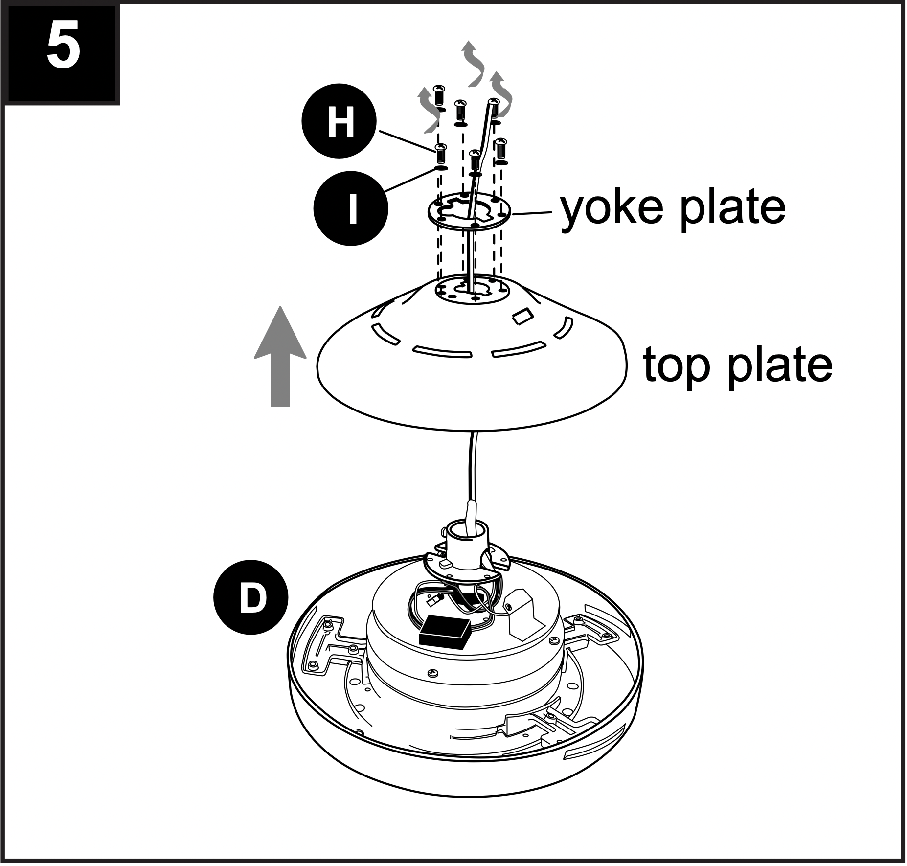
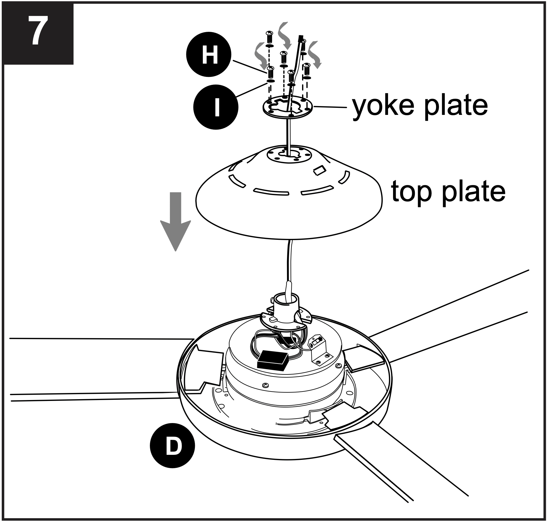
5. Remove 6 motor screws (H) and 6 lock washers (I) from top of motor housing (D). Remove the yoke plate and top plate from motor housing (D).
6. Slide one blade (J) through one of the rectangular openings on center band of motor housing (D). Align holes in blade (J) with holes in blade arm located inside of motor. Attach blade (J) with 3 blade screws (AA) and fiber washers (BB). Repeat for remaining blades (J).
Note: Make sure to completely secure each blade (J) before proceeding to the next.
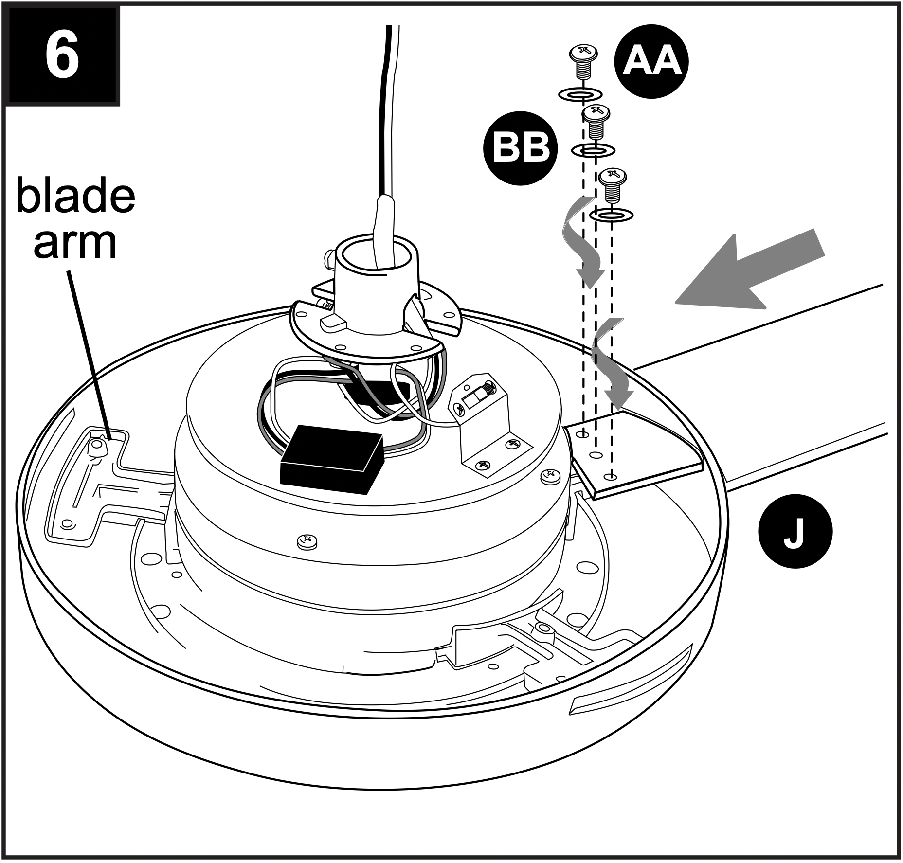
Hardware Used
7. Reattach top plate and yoke plate to motor housing (D) with lock washers (I) and motor screws (H) previously removed in Step 5.
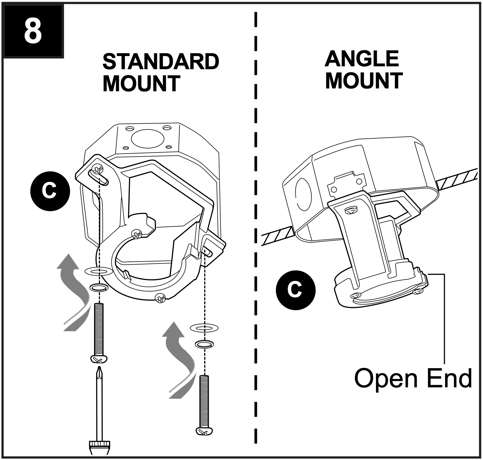
8. Secure mounting bracket (C) to outlet box (not included) using screws, spring washers and flat washers provided with the outlet box.
*NOTE: It is very important you use the proper hardware when installing the mounting bracket (C) as this will support the fan.
IMPORTANT: If using the angle mount, make sure open end of mounting bracket (C) is installed facing the higher point of the ceiling, and ensure the ceiling angle is not steeper than 19°.
DOWNROD-STYLE FAN MOUNTING
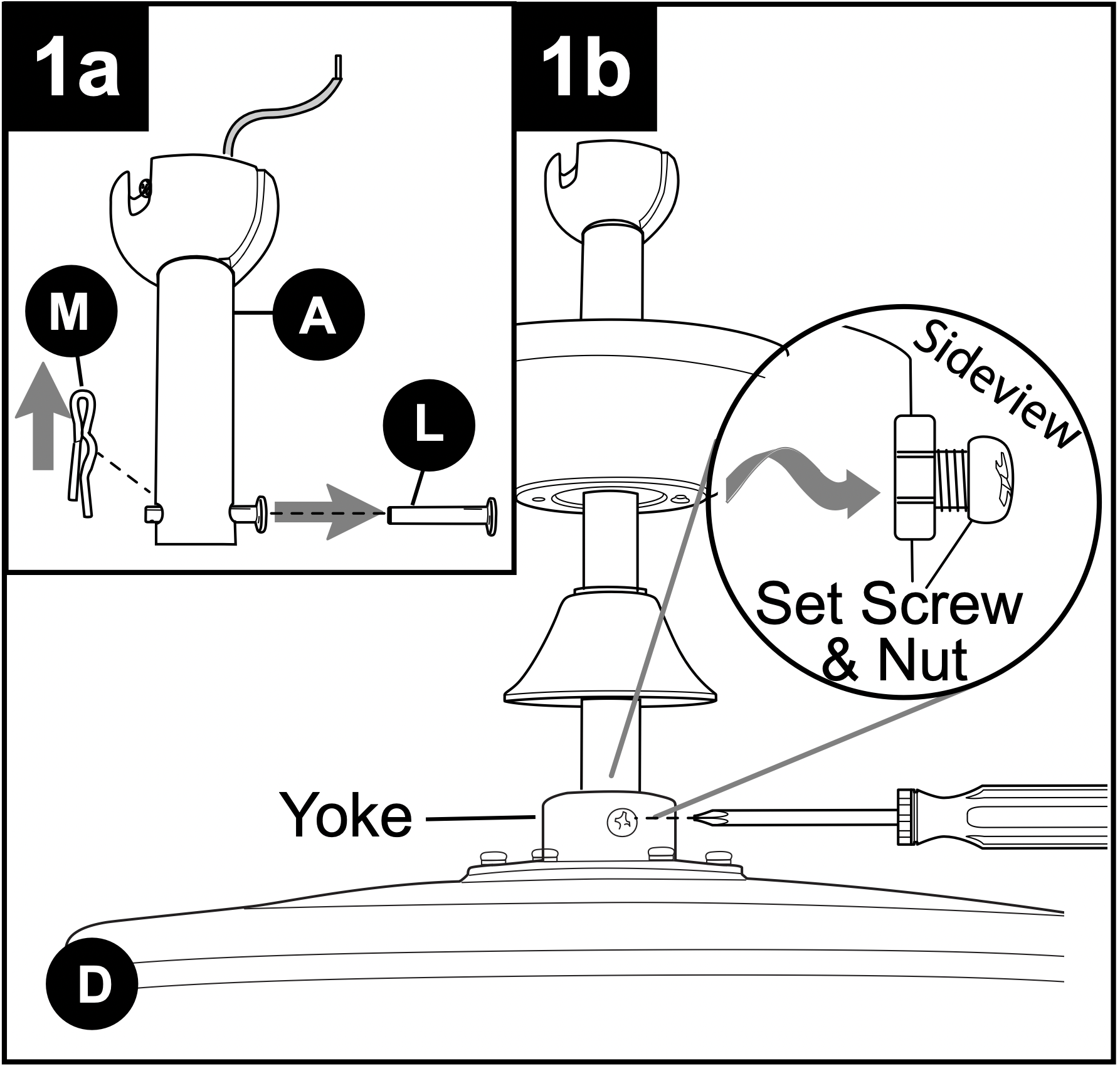
1a. Remove pin (L) and clip (M) from downrod (A).
1b. Partially loosen preassembled set screws and nuts in yoke at top of motor housing (D).
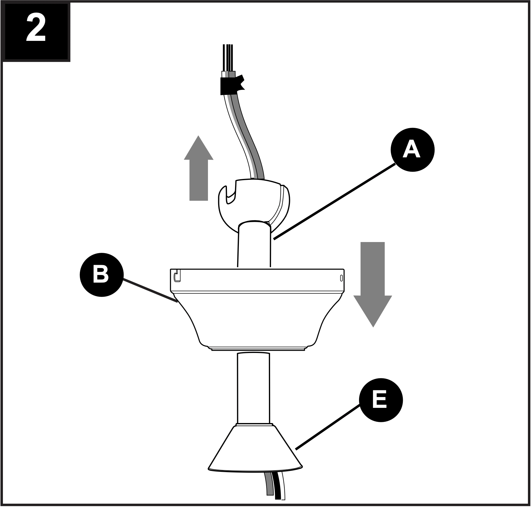
2. Insert downrod (A) through canopy (B), and yoke cover (E). Thread wires from motor housing (D) up through downrod (A).
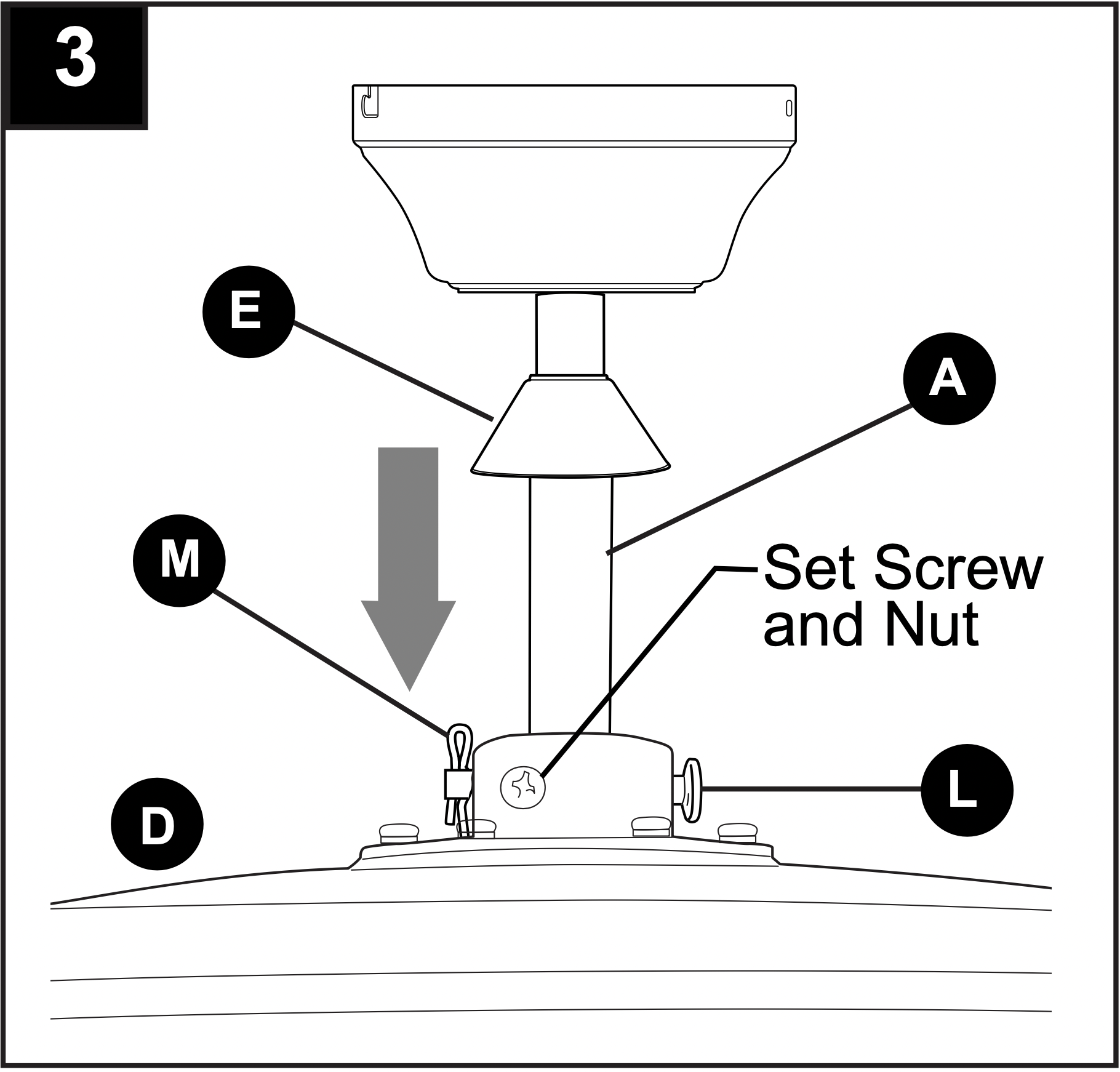
3. Slip downrod (A) into yoke, align holes and re-install pin (L) and clip (M). Tighten set screws and then tighten nuts. Slide yoke cover (E) down until it rests on top of motor housing (D).
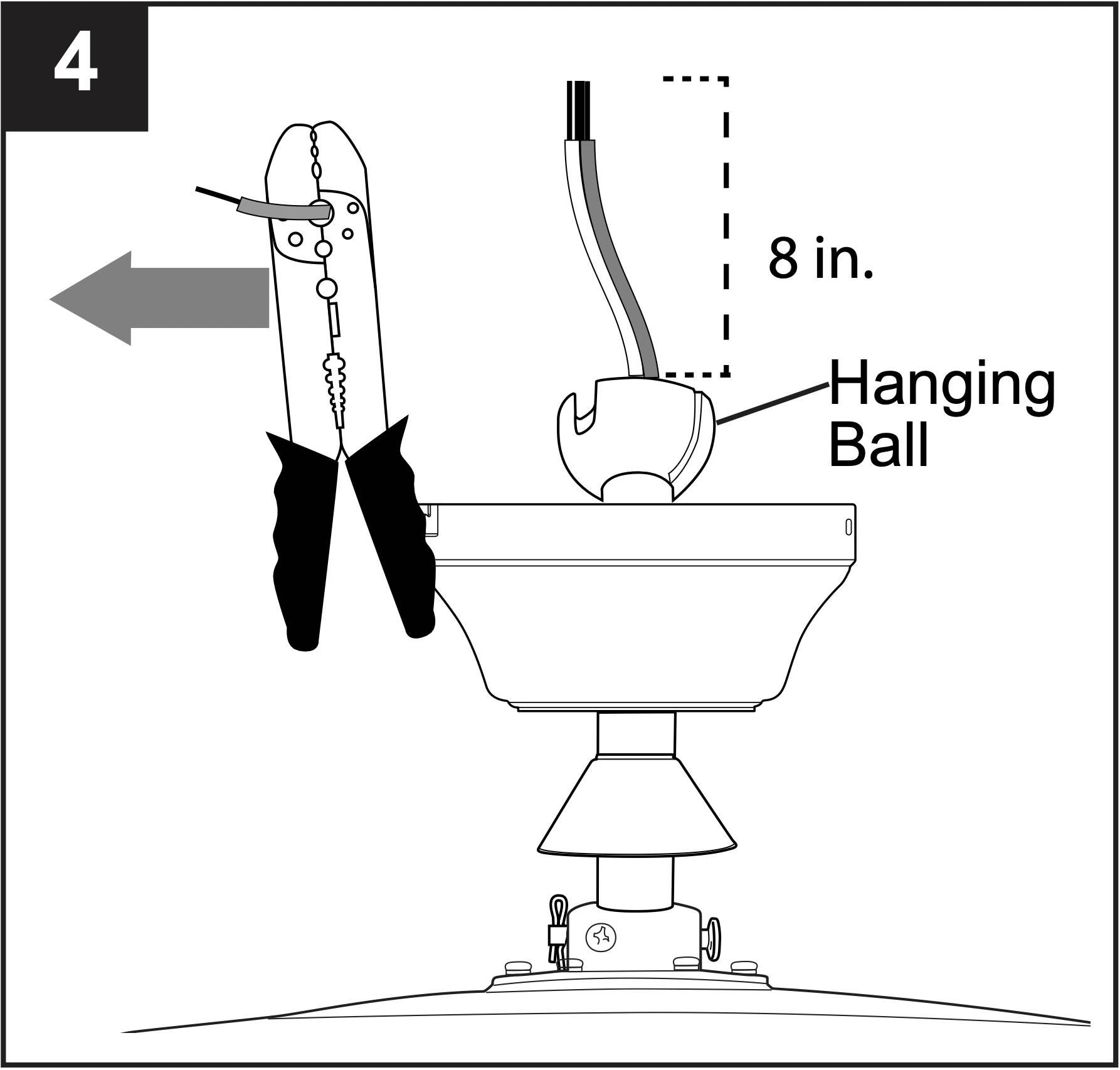
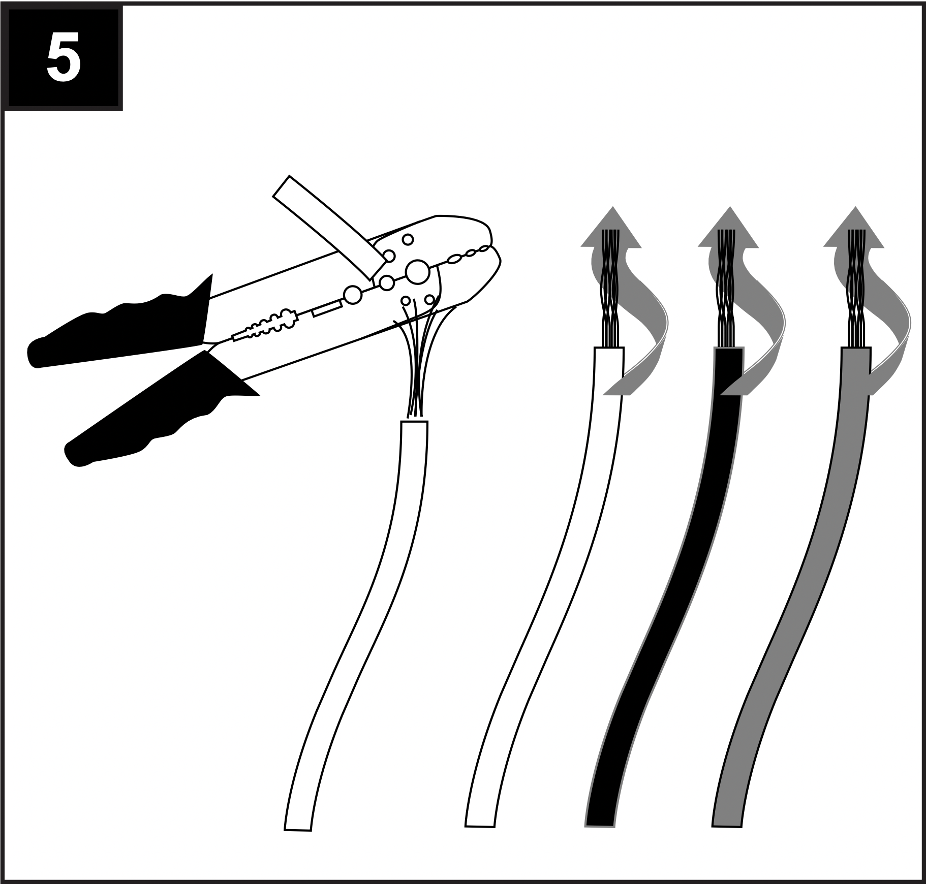
4. Depending on the length of downrod you use, you may need to cut the lead wires back to simplify the wiring. If you decide to cut back the lead wires, it is suggested you do so in the following manner:
Take the lead wires and make sure you have pulled them all the way through the top of the downrod. Start at the TOP of the hanging ball on the downrod and measure 8 in. of lead wire, and then cut the excess wire off with wire cutters (not included).
NOTE: If you do not cut back the lead wires, Steps 4 and 5 are not necessary and you may proceed to Step 6 instead.
5. If you cut back the lead wires in Step 4, strip 1/2 in. of insulation from end of each wire -- WHITE, BLACK, GREEN and BLUE. Twist stripped ends of each strand of wire within the insulation with pliers (not included).
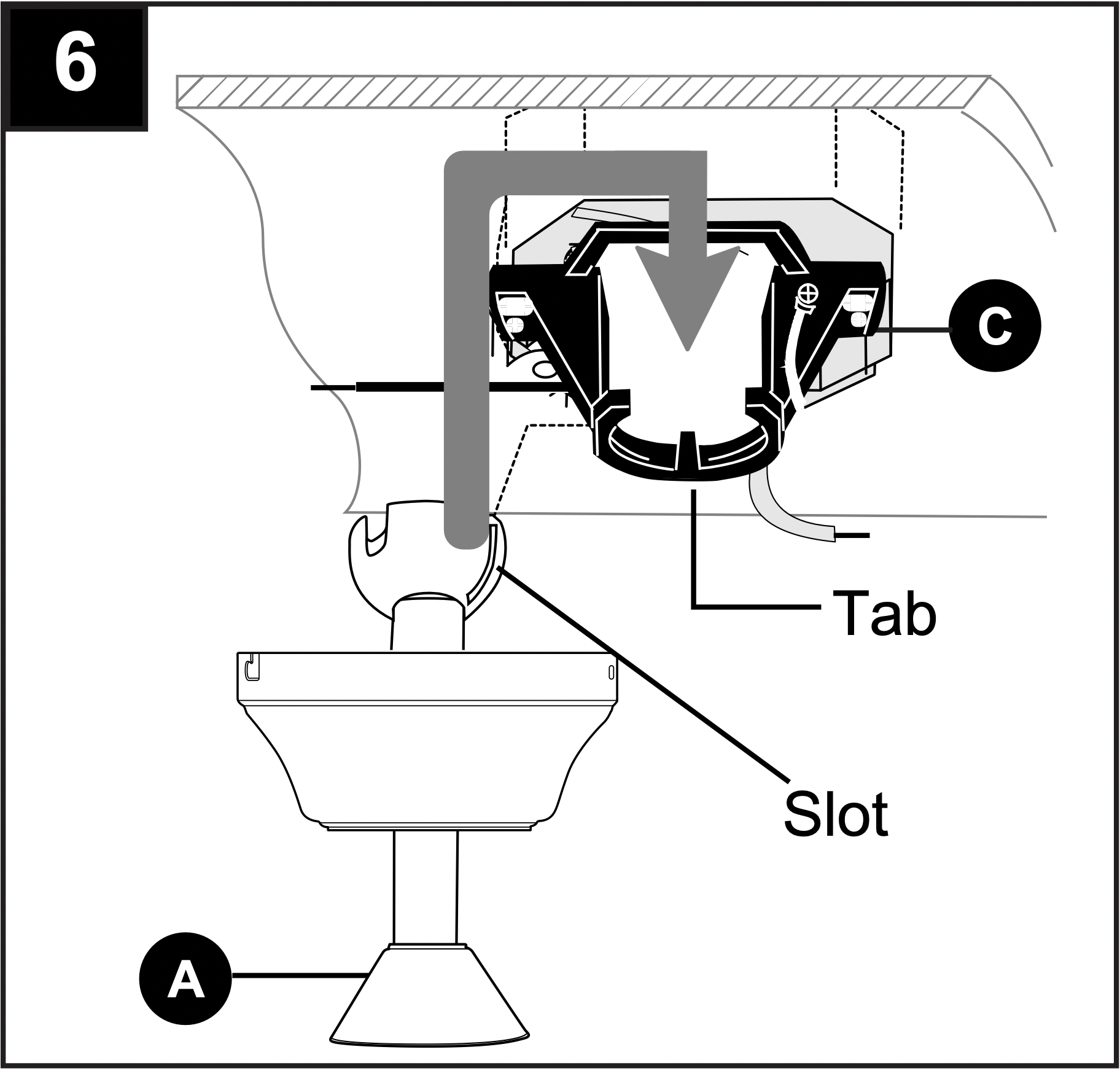
6. Install hanging ball of downrod (A) into opening of mounting bracket (C). Align one of the slots in hanging ball with the tab in mounting bracket (C).
DANGER: Failure to align slot in hanging ball with the tab in mounting bracket (C) may result in serious injury or death.
CLOSEMOUNT-STYLE FAN MOUNTING
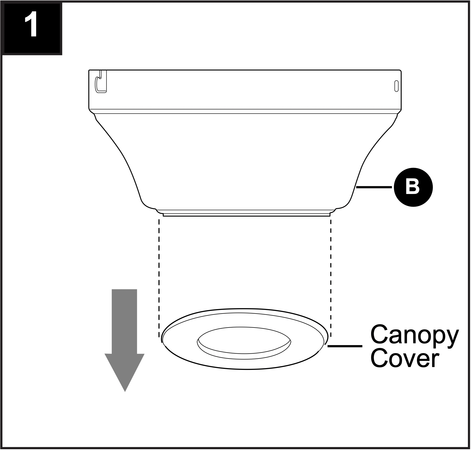
1. Remove preassembled canopy cover from bottom of canopy (B). NOTE: Turn canopy cover to the left (counterclockwise) to remove from canopy (B).
NOTE: The downrod (A), yoke cover (E) and canopy cover are not used in this type of installation.
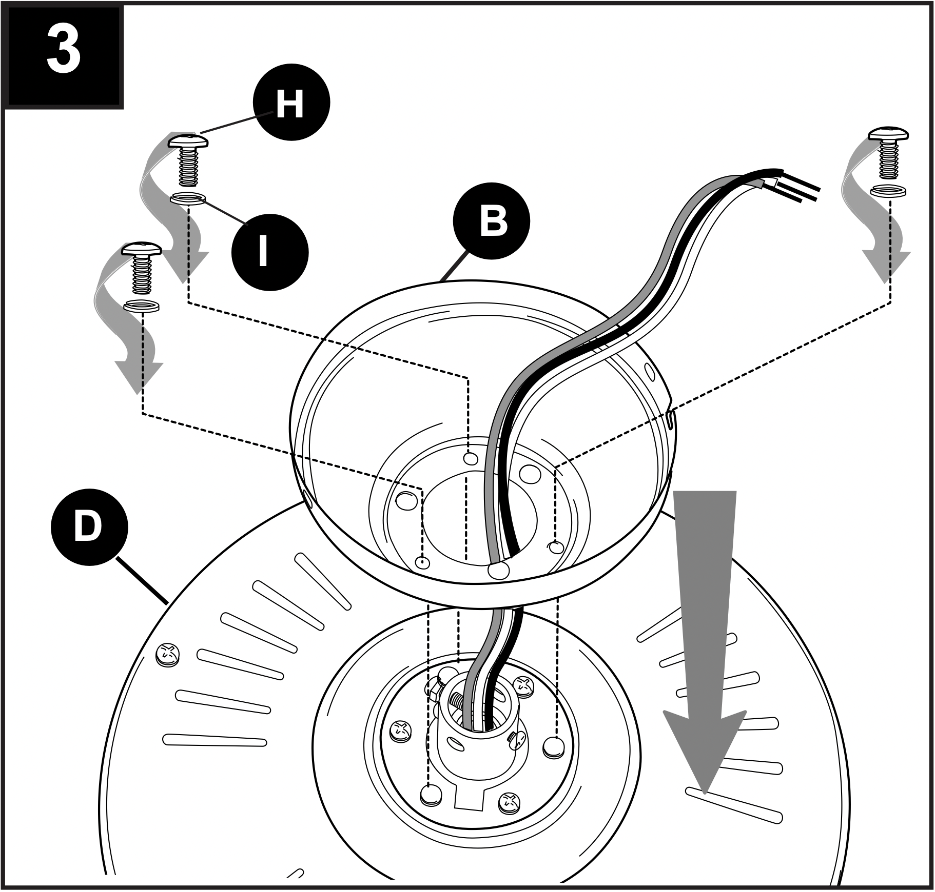
2. Remove every other motor screw (H) and lock washer (I) from top of motor housing (D).
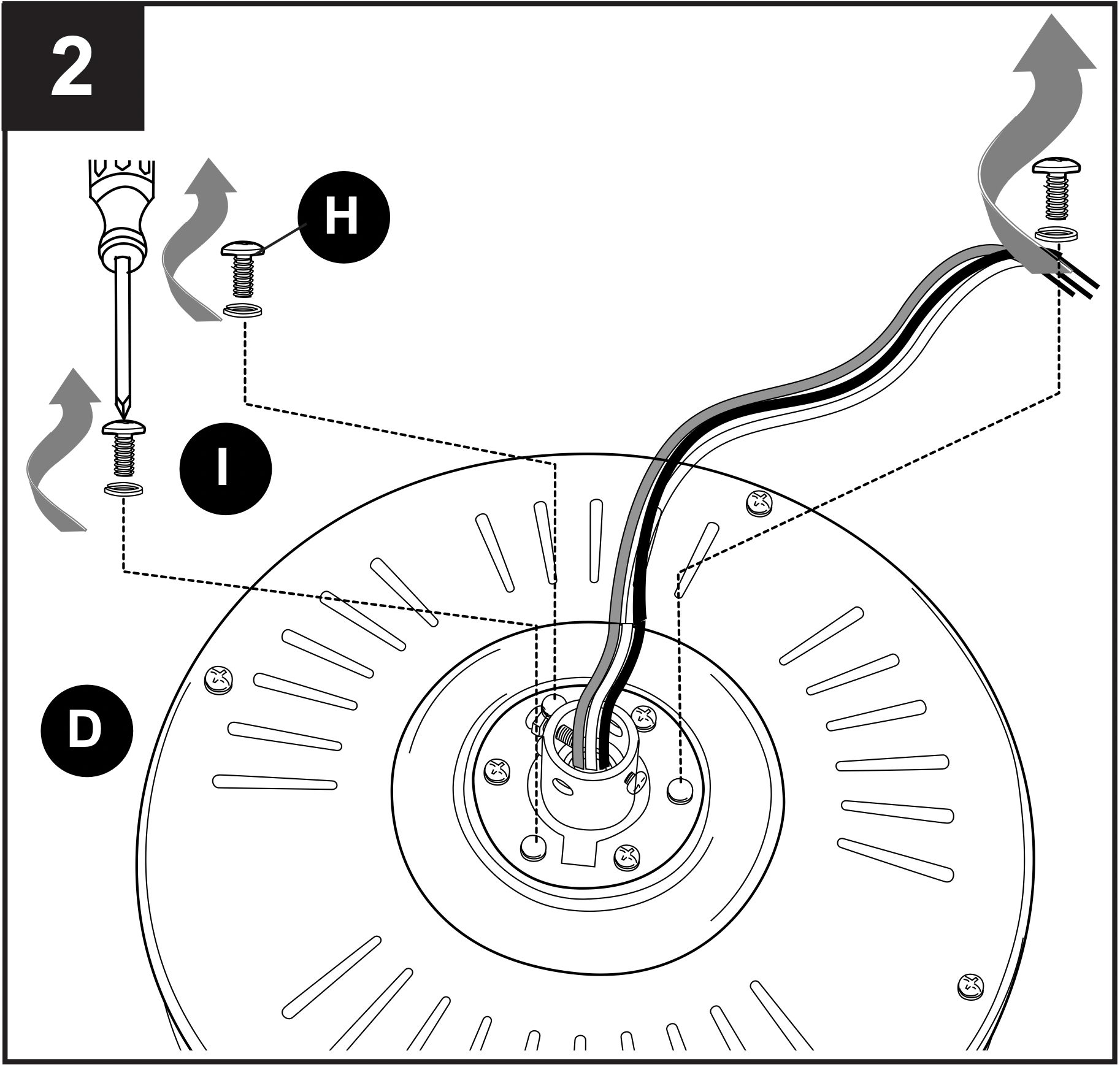
3. Pull wires up through hole in the middle of the canopy (B). Align larger holes in canopy (B) with 3 screws in top of motor housing (D). Attach canopy (B) to motor housing (D) using the three motor screws (H) and lock washers (I) previously removed.
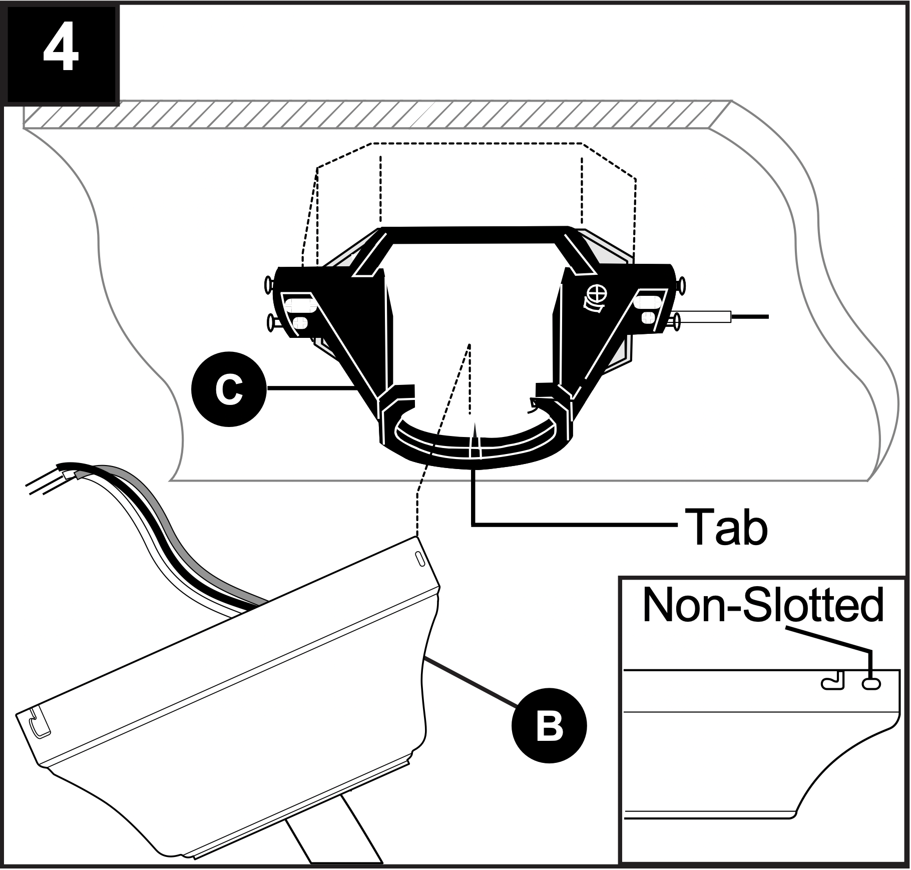
4. Temporarily hang fan on the tab on the mounting bracket (C) using one of the non-slotted holes in the canopy (B).
WIRING
WARNING: To reduce the risk of fire, electrical shock or personal injury, wire connectors provided with this fan are designed to accept only one 12-gauge house wire and two lead wires from the fan. If your house wire is larger than 12-gauge or there is more than one house wire to connect to the corresponding fan lead wires, consult an electrician for the proper size wire connectors to use.
CAUTION: Be sure outlet box is properly grounded and that a ground (green or bare) wire is present.
WARNING: If house wires are different colors than referred to in the following steps, stop immediately. A professional electrician is recommended to determine wiring.
WARNING: Using a full range dimmer switch (not included) to control fan speed will cause a loud humming noise from fan. To reduce the risk of fire or electrical shock, do NOT use a full range dimmer switch to control fan speed.
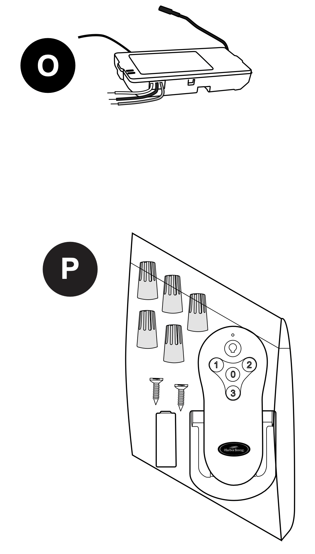
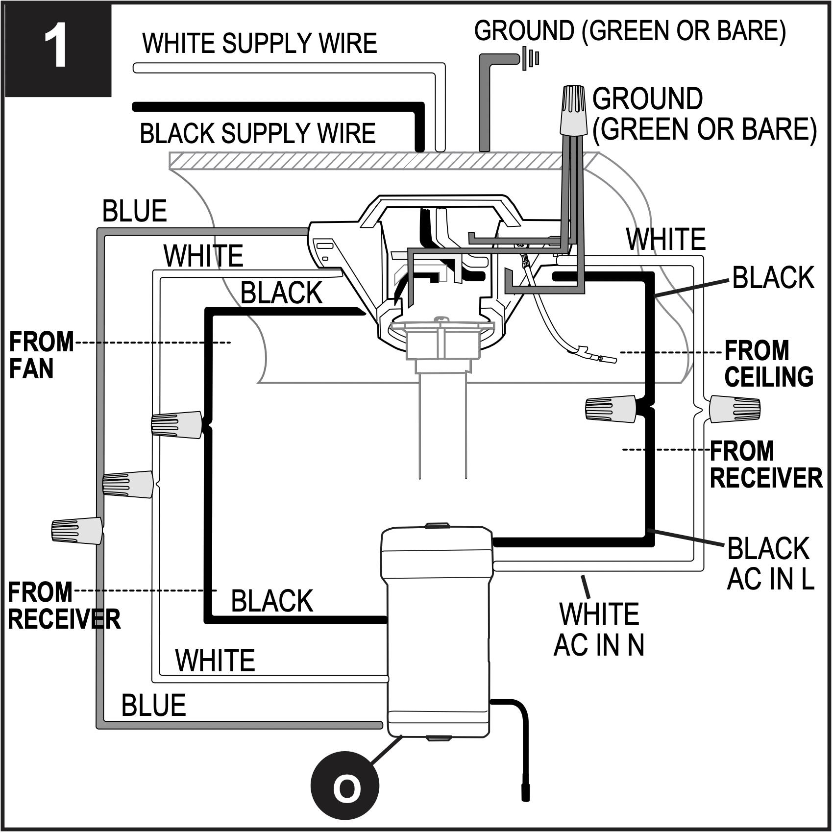
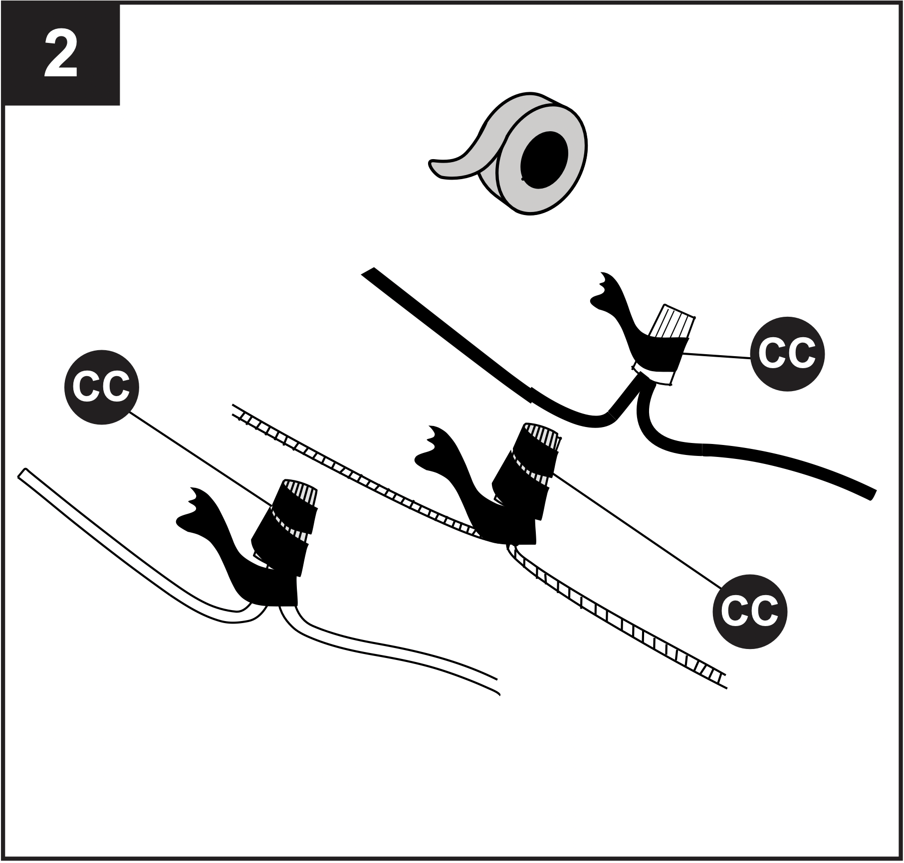
1. Make the necessary wiring connections for remote control operation as detailed below and in the figure. For each wire connection, use one of the wire connectors (CC), making sure to screw wire connector (CC) on in a clockwise direction.
CAUTION: Assistance from another person is recommended for this step.
Connect all GROUND (GREEN) wires from fan (on downrod (A), if applicable, and mounting bracket (C)) to BARE/GREEN supply wire from ceiling.
Connect BLACK wire (labeled AC IN L) from remote control receiver (O) to BLACK supply wire from ceiling.
Connect WHITE wire (labeled AC IN N) from remote control receiver (O) to WHITE supply wire from ceiling.
Connect WHITE wire (labeled TO MOTOR N) from remote control receiver (O) to WHITE wire from motor housing (D).
Connect BLACK wire (labeled TO MOTOR L) from remote control receiver (O) to BLACK wire from motor housing (D).
Connect BLUE wire (labeled FOR LIGHT) from remote control receiver (O) to BLUE wire from motor housing (D).
2. Wrap electrical tape (not included) around each individual wire connector (CC) down to the wire.
WARNING: Make sure no bare wire or wire strands are visible after making connections. Place GREEN and WHITE connections on opposite side of the outlet box from the BLACK and BLUE (if applicable) connections.
Hardware Used
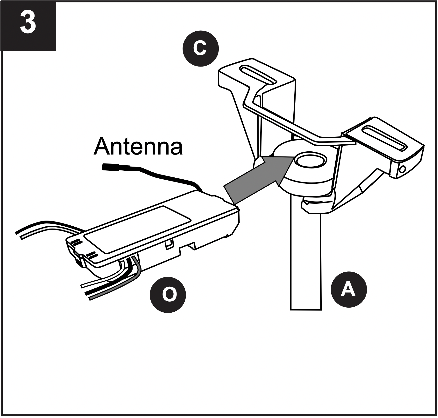
3. Gently slide remote control receiver (O) flat-side up into mounting bracket (C). Turn spliced/taped wires upward and gently push wires and wire connectors (CC) into outlet box. Let antenna from remote control receiver (O) hang to the side.
NOTE: The remote control included with this fan meets the following requirements:
a. Not for use with solid state fans.
b. Electrical rating: 120V / 60 Hz; motor amps:1.25 MAX.
Should you choose to use a different remote control with this fan, it must also meet these same requirements.
FINAL INSTALLATION
1. Lift canopy (B) to mounting bracket (C) again, aligning slotted holes in canopy (B) with loosened canopy mounting screws (G) in mounting bracket (C). Twist canopy (B) clockwise to lock. Re-insert the two canopy mounting screws (G) previously removed (Step 4, page 6) and tighten all canopy mounting screws (G) securely.
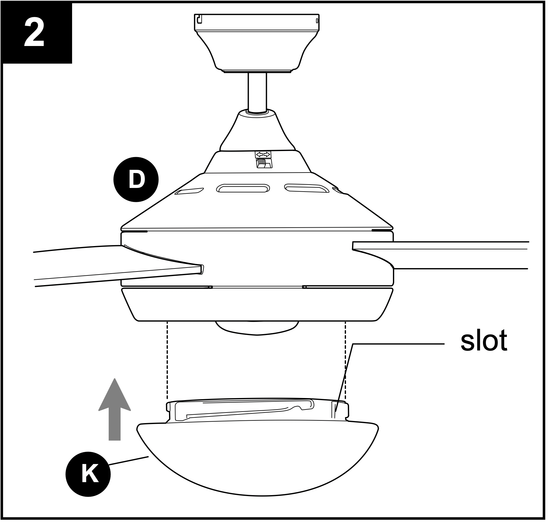
2. Align slots on glass shade (K) with protrusions on underside of motor housing (D). Turn glass shade (K) clockwise until it no longer turns.
NOTE: Pull down gently on the glass shade (K) to make sure it is secured completely.
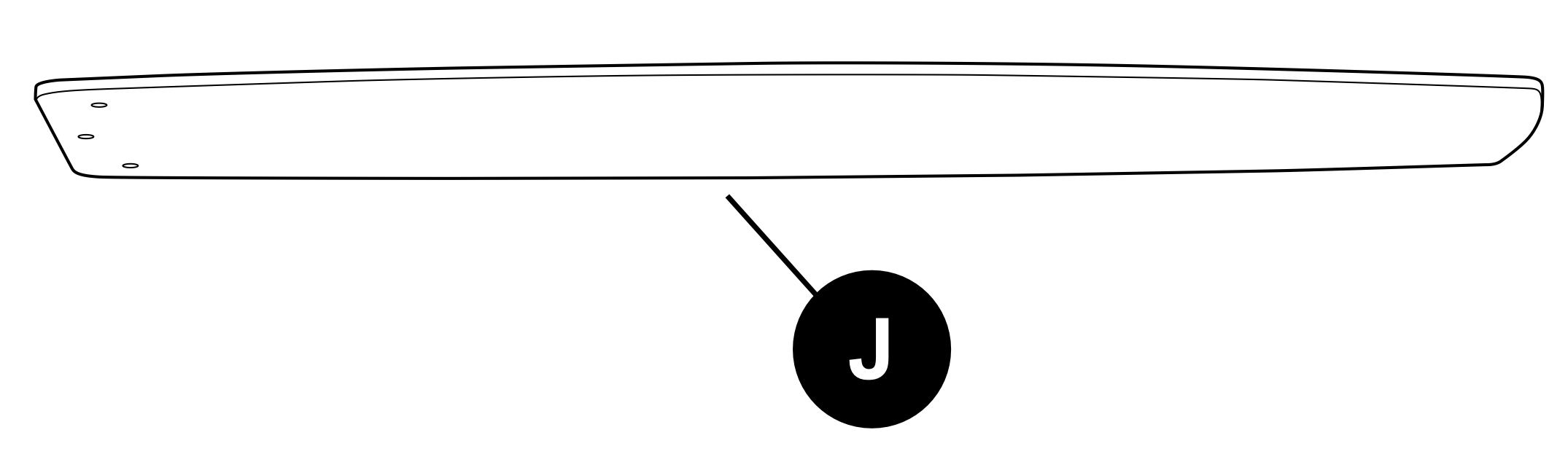
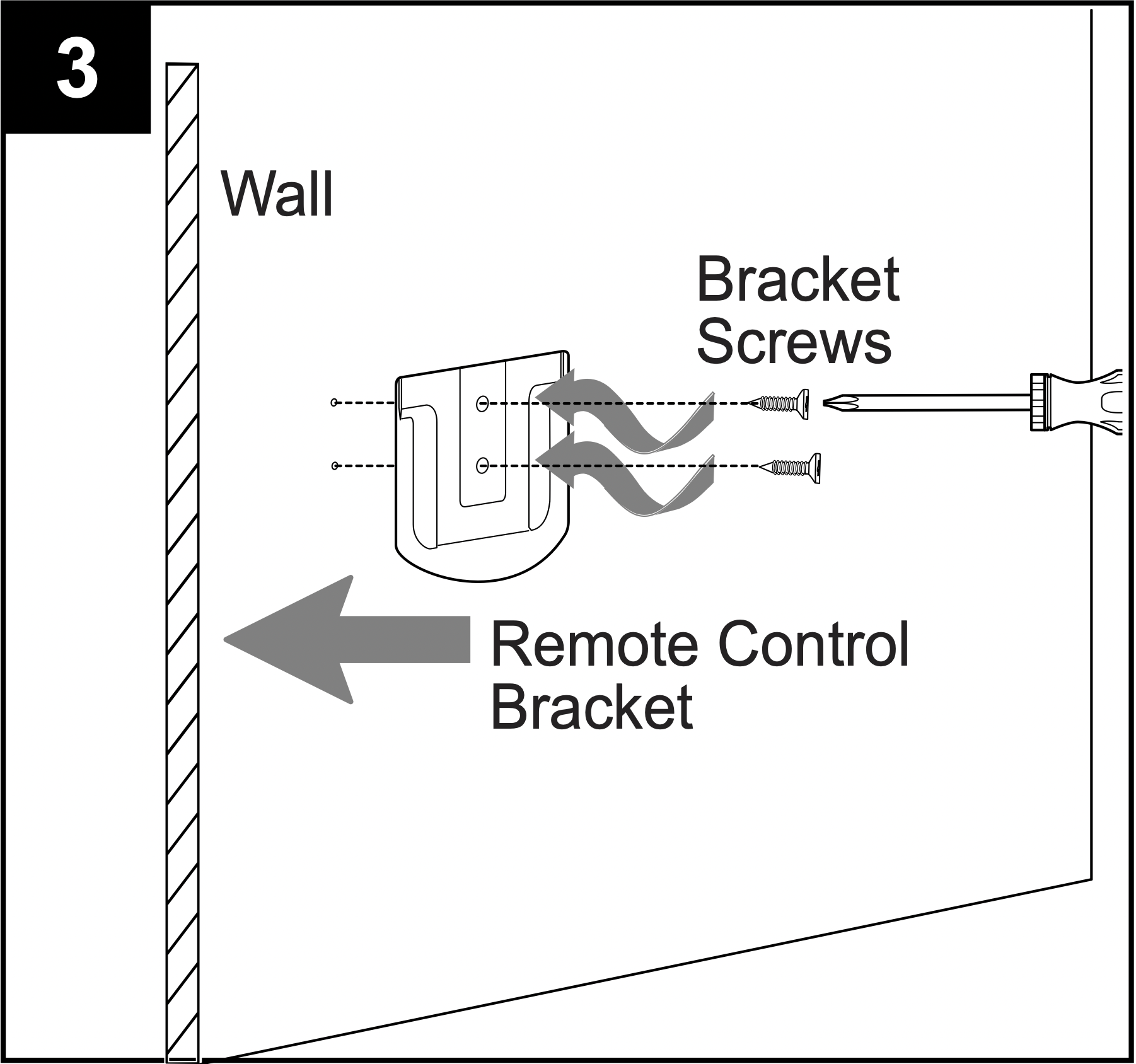
3. If you wish to use the remote control bracket from remote pack (P), install screws from remote pack (P) through bracket and into the desired installation site. The remote control transmitter from remote pack (P) rests inside the bracket.
OPERATING INSTRUCTIONS
CAUTION: The remote control transmitter can be programmed to multiple receivers or fans. If this is not desired, turn wall switch off to any other programmable receiver or fan.
FCC Compliance Notice for Remote Control
Modifications not approved by the party responsible for compliance could void the user's authority to operate the equipment.
*NOTE: This equipment has been tested and found to comply with the limits for a Class B digital device, pursuant to Part 15 of the FCC Rules. These limits are designed to provide reasonable protection against harmful interference in a residential installation. This equipment generates, uses and can radiate radio frequency energy and, if not installed and used in accordance with the instructions, may cause harmful interference to radio communications. However, there is no guarantee that interference will not occur in a particular installation. If this equipment does cause harmful interference to radio or television reception, which can be determined by turning the equipment off and on, the user is encouraged to try to correct the interference by one or more of the following measures:
* Reorient or relocate the receiving antenna.
* Increase the separation between the equipment and receiver.
* Connect the equipment into an outlet on a circuit different from that to which the receiver is connected.
Consult the dealer or an experienced radio/TV technician for help.
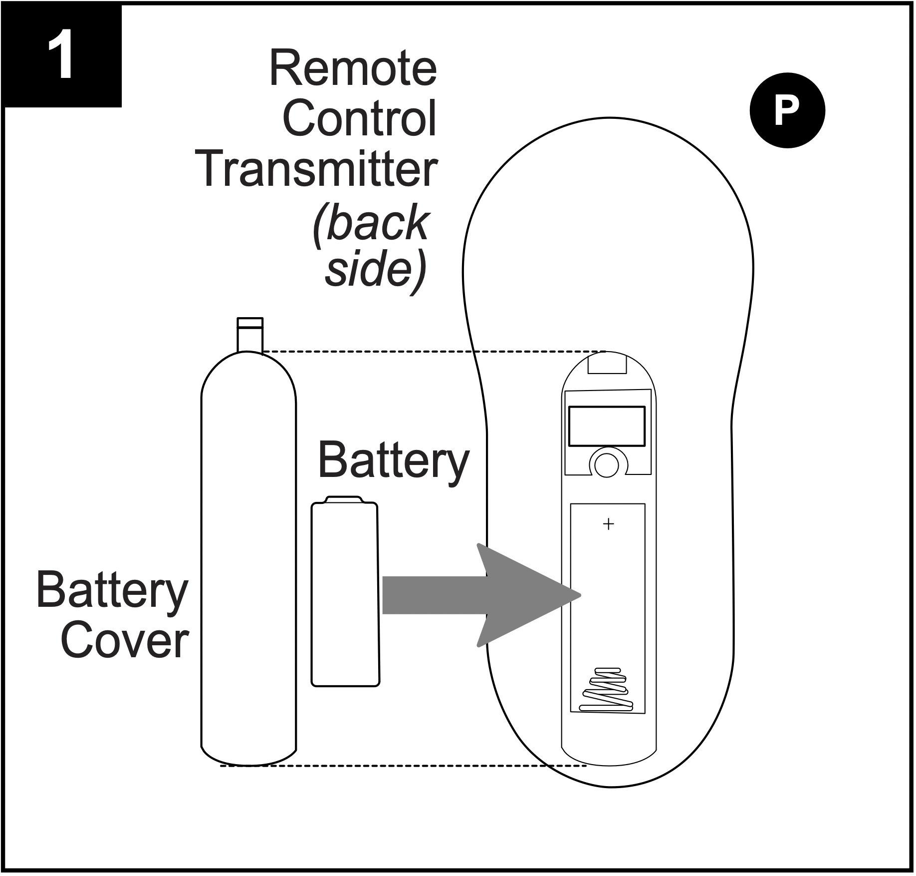
1. Remove battery cover from back of remote control transmitter in remote pack (P). Install battery from remote pack (P) with positive (+) end toward top of remote control transmitter.
Replace battery cover on remote control transmitter.
WARNING: Choking Hazard - Small parts. Keep battery away from children.
CAUTION: “DO NOT DISPOSE OF BATTERIES IN FIRE, BATTERIES MAY EXPLODE OR LEAK.” - When disposing of household alkaline batteries, it is best to check with your local and state recycling or household hazardous waste coordinators concerning the specifics of the program in your area.
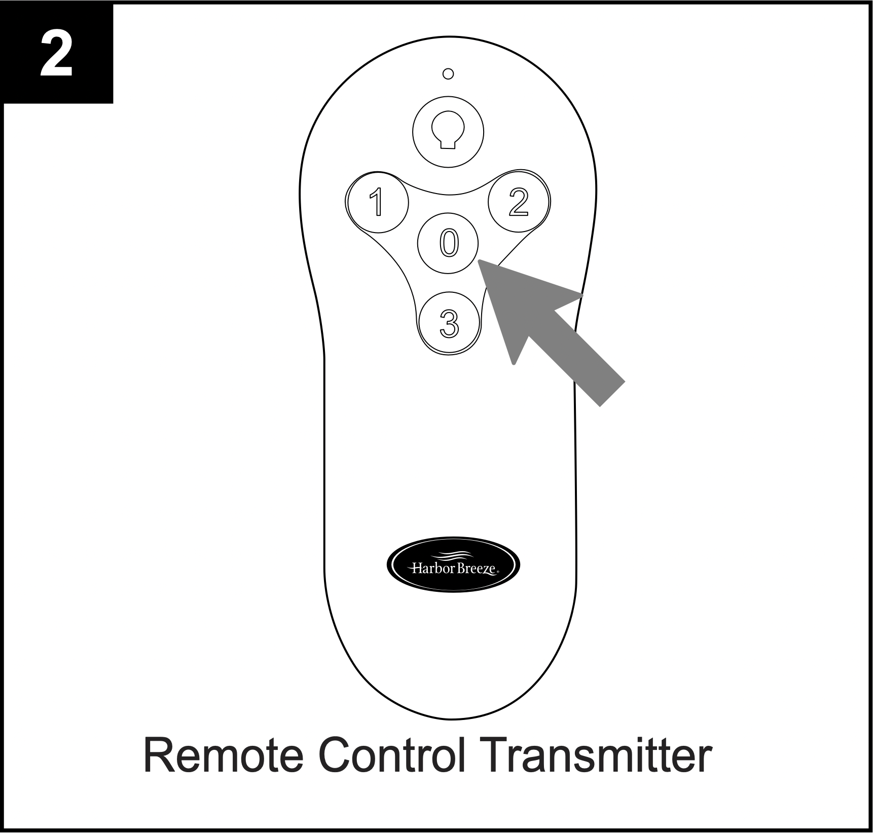
2. Restore electrical power. Within 30 seconds of restoring electrical power, press and hold the “0” button on the remote control transmitter for 5 seconds or until light on the fan blinks twice. Use the remote control transmitter to test the light and fan functions to confirm the learning process is complete.
NOTE: Remove protective covering from front of remote control transmitter and discard.
IMPORTANT: To prevent damage to remote control transmitter, remove the battery if not used for long periods. Store the remote control transmitter away from excess heat or humidity.
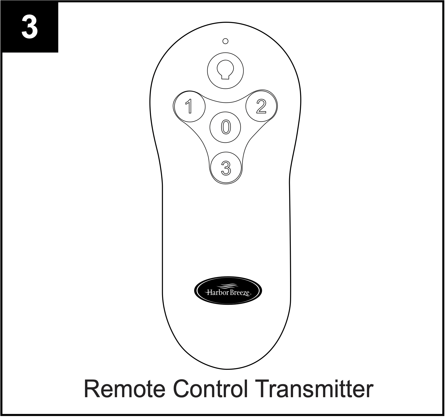
3. Operation buttons on the panel of the remote control transmitter:
|
3 button
|
for fan HIGH speed |
|
2 button
|
for fan MEDIUM speed |
| 1 button |
for fan LOW speed
|
| 0 button |
to turn fan OFF
|
 button button |
to turn light ON or OFF
|
Tap button quickly to turn lights off or on. Hold button down to increase or decrease lights. If you press button in excess of 0.7 seconds, it becomes a dimmer. The lights vary cyclically in 8 seconds. The light button has an auto resume function, which keeps the light at the same brightness as the last time it was turned off.
NOTE: Most CFLs are NOT compatible for use with dimmer controls.
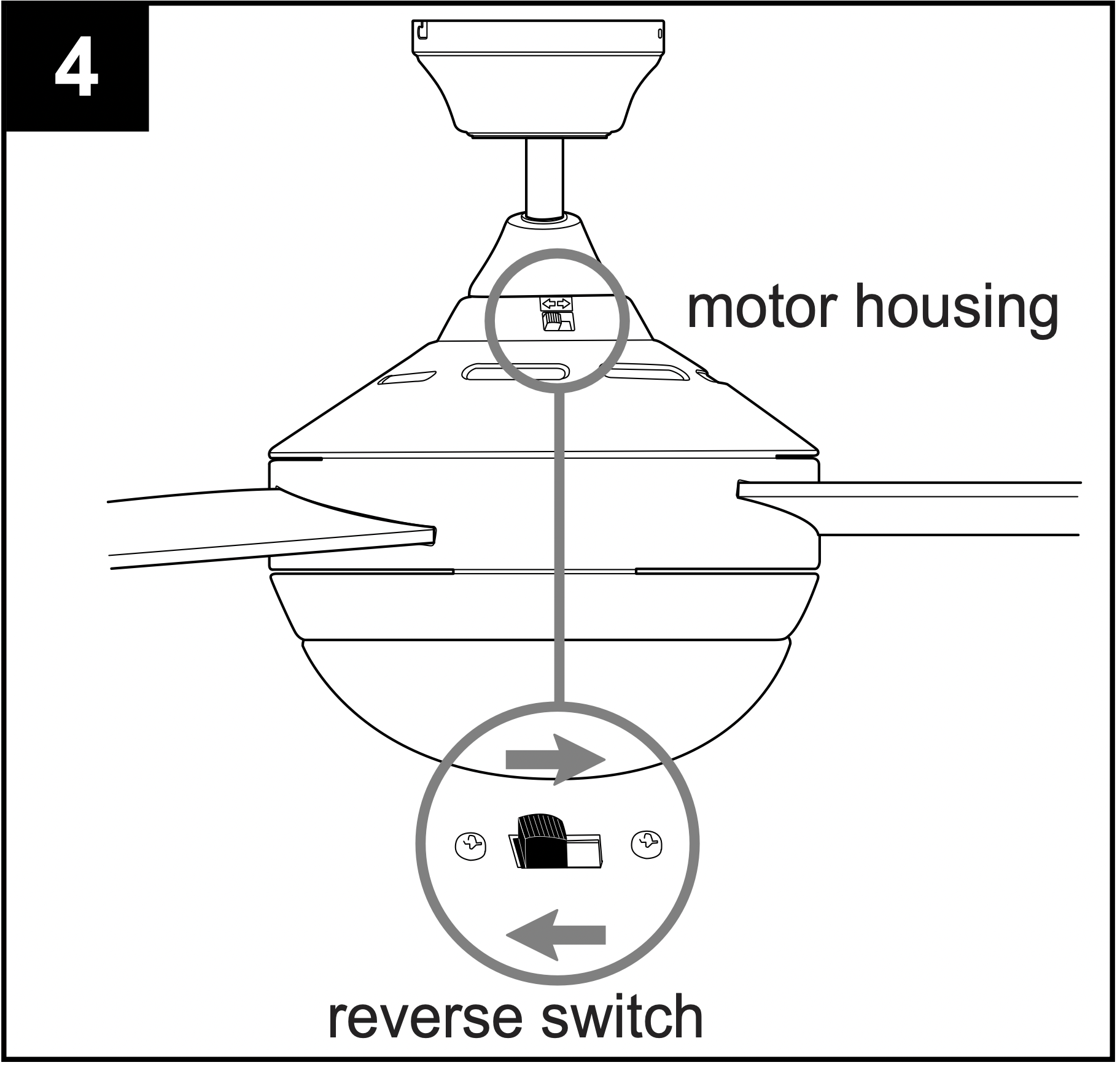
4. Use the fan reverse switch on the switch housing to optimize the fan for seasonal performance. A ceiling fan will allow you to raise your thermostat setting in summer and lower your thermostat setting in winter without feeling a difference in your comfort.
CAUTION: Turn fan off at wall switch and let blades (J) come to a complete stop before manually activating the reverse switch.
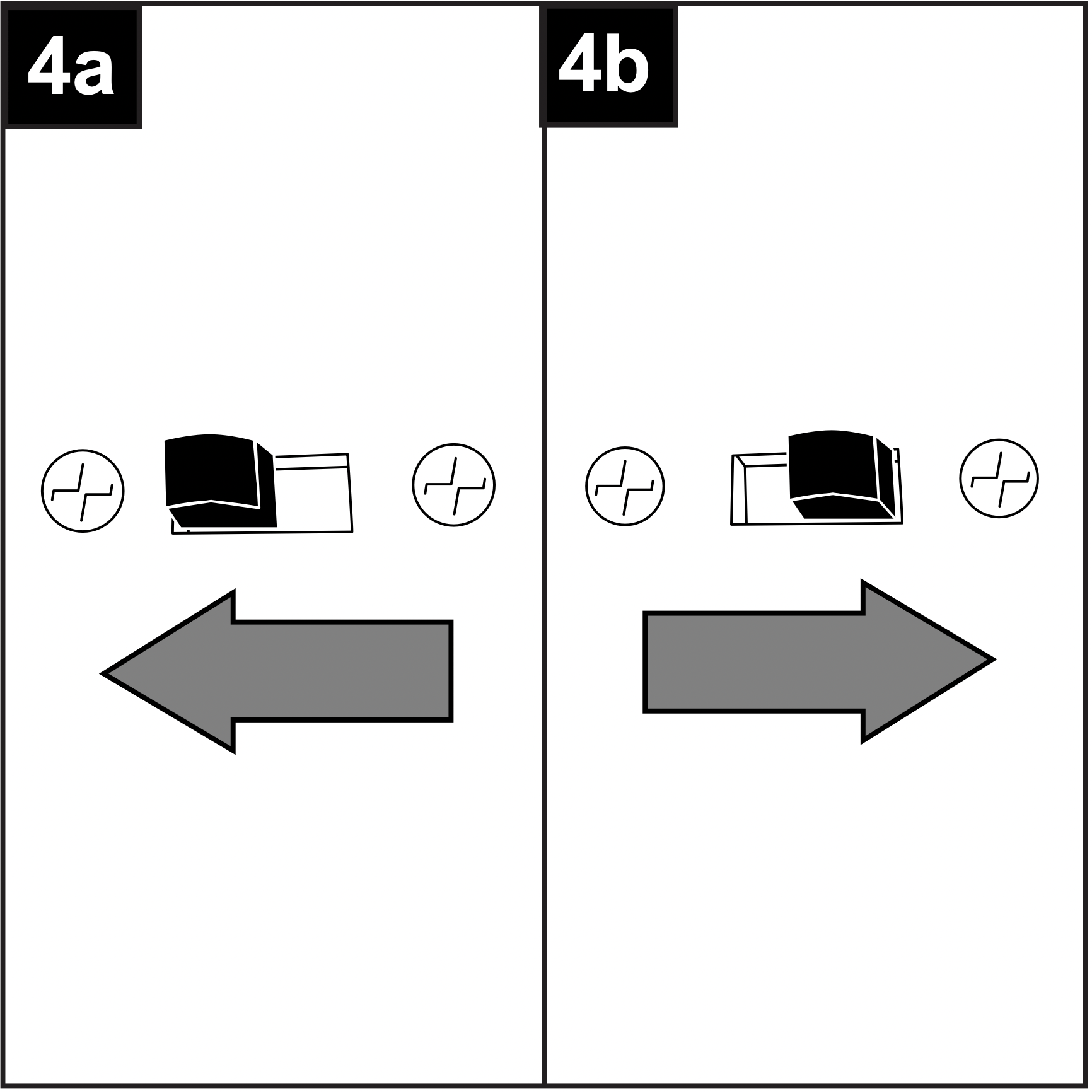
4a. In warmer weather, setting the reverse switch in the LEFT position will result in downward airflow creating a wind chill effect.
4b. In cooler weather, setting the reverse switch in the RIGHT position will result in upward airflow that can help move stagnant, hot air off the ceiling area.
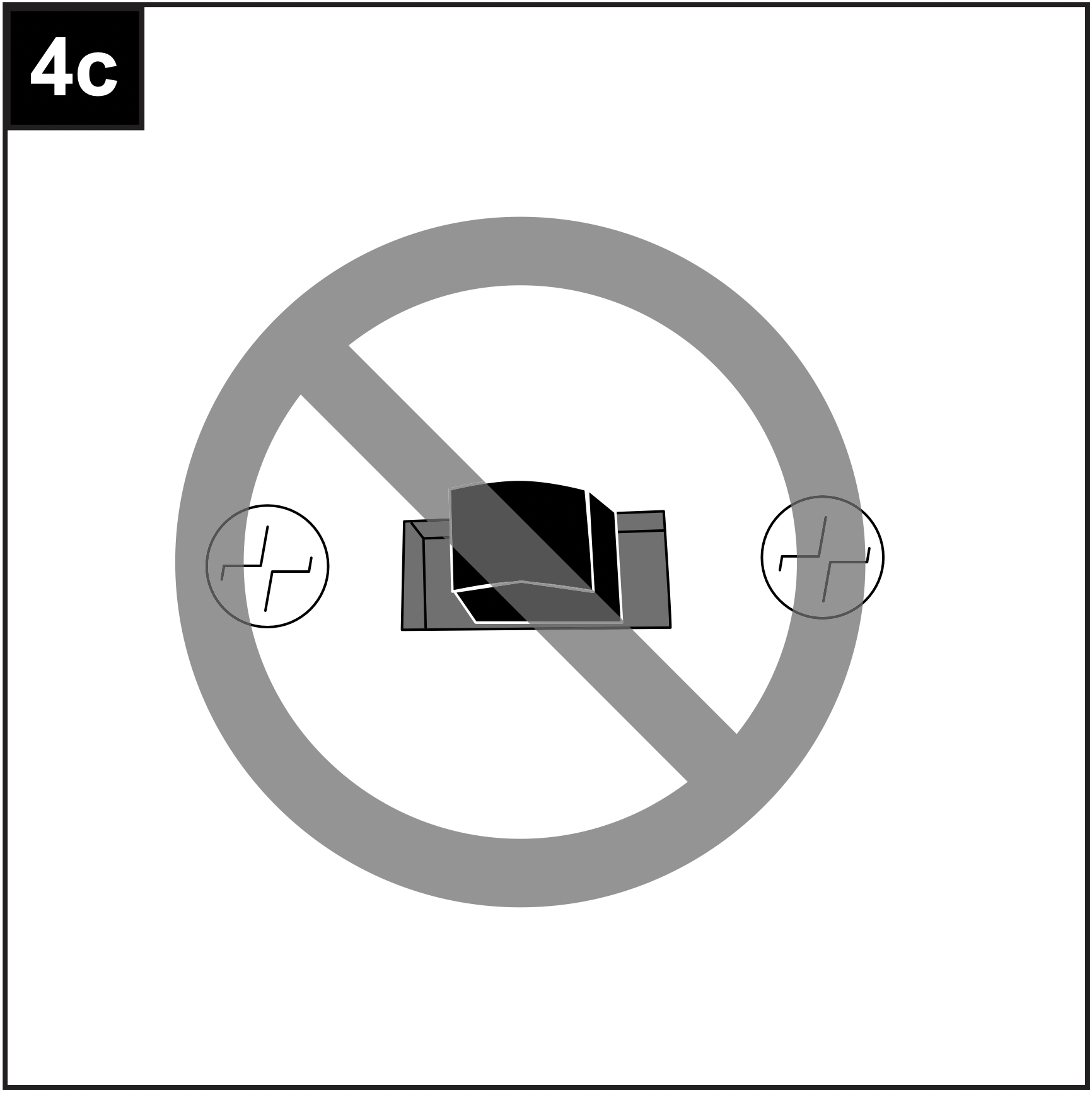
4c. IMPORTANT: Reverse switch must be set either completely LEFT or completely RIGHT for fan to function. If the reverse switch is set in the middle position, fan will not operate.
CARE AND MAINTENANCE
At least twice each year, lower canopy (B) to check downrod (A) assembly, and then tighten all screws on fan. Clean motor housing (D) with only a soft brush or lint-free cloth to avoid scratching the finish. Clean blades (J) with a lint-free cloth. You may occasionally apply a light coat of furniture polish to wood blades for added protection.
IMPORTANT: Shut off main power supply before beginning any maintenance. Do not use water or a damp cloth to clean the ceiling fan.
TROUBLESHOOTING
WARNING: Before beginning work, shut off the power supply to avoid electrical shock.
| PROBLEM |
POSSIBLE CAUSE
|
CORRECTIVE ACTION |
|
Fan does not move.
|
- Reverse switch not engaged.
- Power is off or fuse is blown.
- Faulty wire connection.
- Learning code process between fan and remote control transmitter may not have been successful and learning code was not activated.
|
- Push switch firmly either left or right.
- Turn power on or check fuse.
- Turn power off. Loosen canopy and check all connections.
- Turn off power and repeat instructions in Step 2 on page 16.
|
|
Noisy operation.
|
- Blades are loose.
- Cracked blade.
- Full range dimmer switch.
- Fan is new.
|
- Tighten all blade screws.
- Replace blade.
- Replace with an approved speed control device.
- Allow fan a “break in” period of a few days, especially when running the fan at Medium and High speeds.
|
|
Excessive wobbling.
|
- Blades are loose.
- Unbalanced blades.
- Fan not securely mounted.
- Fan too close to vaulted ceiling.
- Set screw(s) on motor housing yoke is (are) not tightened properly.
|
- Tighten all blade screws.
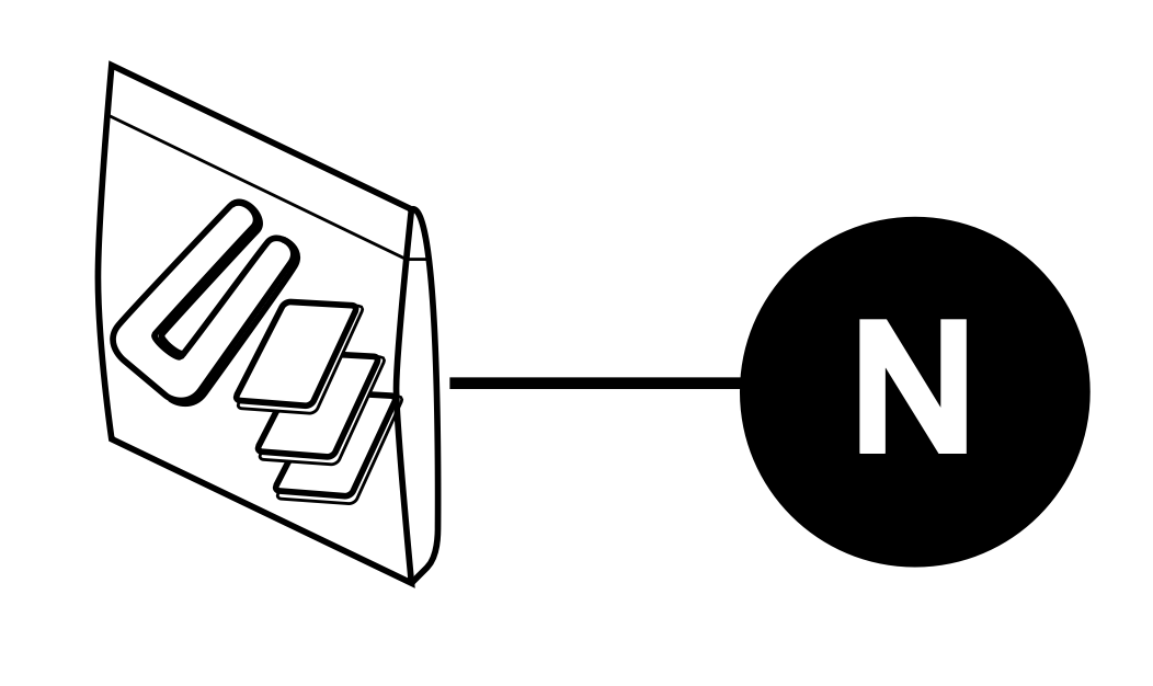
- Switch one blade with a blade from the opposite side or use balancing kit (N).
- Turn power off. Carefully loosen canopy and verify that mounting bracket is secure.
- Use a longer downrod or move fan to another location.
- Tighten yoke set screw(s) securely.
|
|
Fan operates but light fails.
|
- Wires in canopy not wired properly.
- Wall switch to fan is off.
|
- Check wires in canopy and, if necessary, re-wire according to instructions on pages 12and 13.
- Make sure that wall switch to fan is on.
|