Loading ...
Loading ...
Loading ...
30
Wireless
®
13
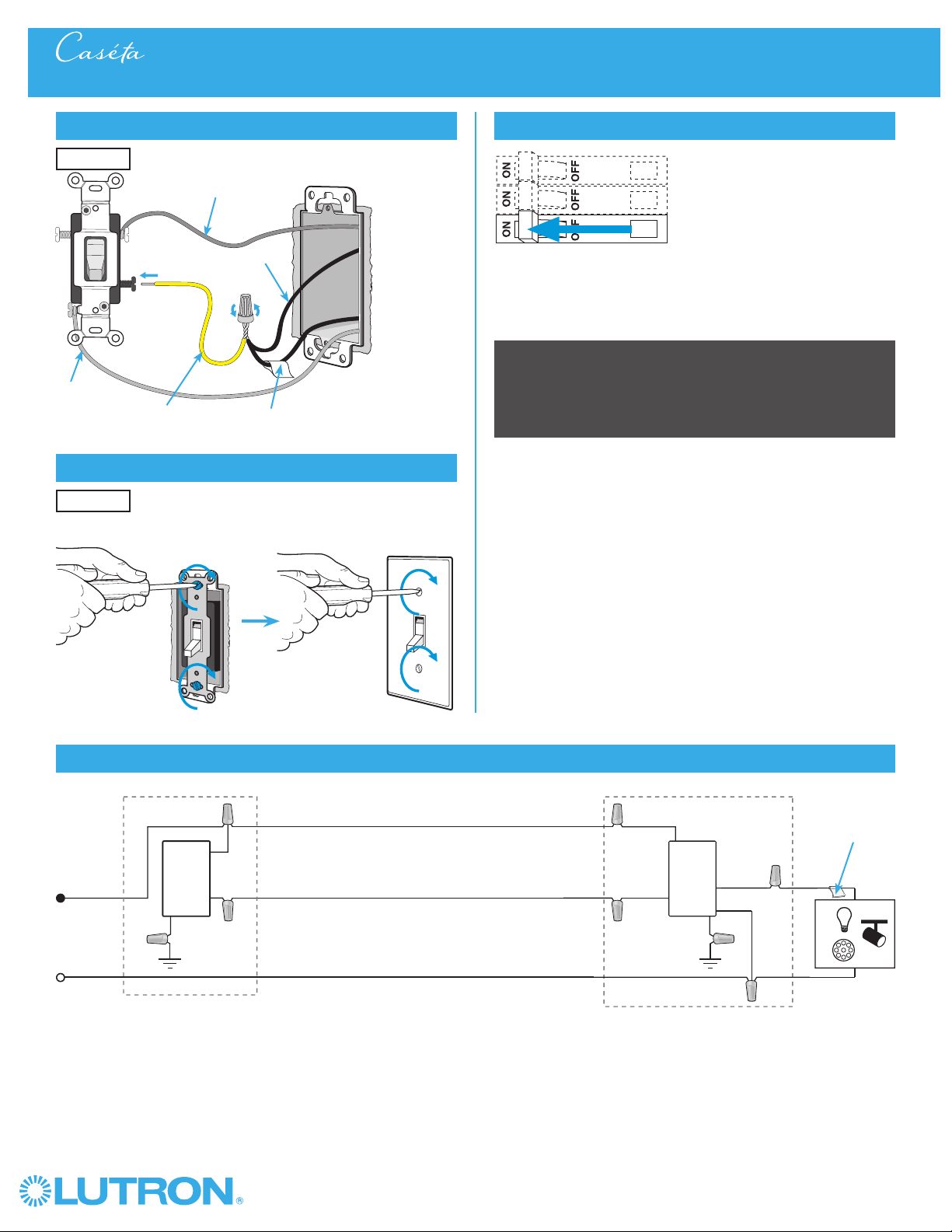
Remount existing switch
14
Turn power on at circuit breaker
3-Way Installation - Caséta® Wireless In-Wall Neutral Switch with Mechanical Toggle Switch
Location 2
Location 2
Neutral
Toggle
Switch
Line / Hot
Traveler
Caséta®
Wireless
Switch*
Load
LED
DEL
INC /
HAL
Schematic Diagram
Traveler
Tagged Wire
Ground
(Green)
Red
White
Blue
Black
Important note: Pico® remote control
(optional)
If you would like to pair a Pico® remote control to the Caséta® Wireless
in-wall switch, please follow the procedure described in the quick-start
guide that came with your switch.
12b
Modify wiring for existing toggle switch
Different Color Screw /
Tagged Wire
Jumper wire
(included in box)
Noted wire color
from Step 8
Remaining wire
Ground
(Green / Bare
Copper)
* Switch may be installed in either location.
Note: The red wire must be connected to the load and the black wire must be connected to Line/Hot. The product will not work if the wires
are reversed.
Loading ...
Loading ...
Loading ...