Loading ...
Loading ...
Loading ...
11
Wireless
®
7
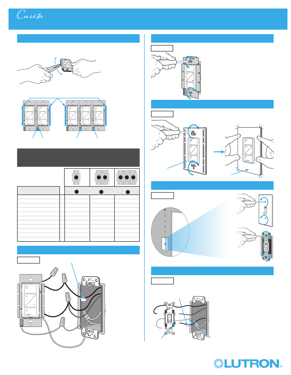
Remove side sections (if necessary)
Do not remove outside side sections
on dimmers at the end of gang.
Each dimmer has inside
side sections removed.
Dimmer in the middle has all
side sections removed.
Total Dimmable LED Wattage Incandescent/Halogen Total Wattage
0 W + 1000 W 800 W 600 W
1 W – 25 W + 900 W 750 W 550 W
26 W – 50 W + 800 W 700 W 500 W
51 W – 75 W + 700 W 600 W 450 W
76 W – 100 W + 600 W 500 W 400 W
101 W – 125 W + 500 W 400 W 300 W
126 W – 150 W + 400 W 300 W 200 W
151 W – 175 W + 300 W 200 W 100 W
176 W – 200 W + 200 W 100 W 50 W
201 W – 225 W + 100 W 50 W 0 W
226 W – 250 W + 0 W 0 W 0 W
A
B
C
B
B B
C
B
A
8
Connect the Caséta® Wireless dimmer
Tagged Wire
Ground
(Green Wire)
Red
White *
*
If available,
connect the
neutral wire from
the wallbox to the
white wire on the
dimmer. If neutral
is not available,
cap the white
wire with a wire
connector.
Neutral required
for: MLV loads,
LED drivers,
PHPM-PA,
PHPM-3F,
GRX-TVI.
Black
Blue
9
Mount the Caséta® Wireless dimmer
10
Attach the wallplate
‘snap’
11
Remove existing switch from wall at Location 2
3-Way Installation - Caséta® Wireless In-Wall PRO Dimmer with Pico® Remote Control
12
Tag and disconnect wires from the switch
Ground (Green / Bare Copper)
Different
Color
Screw
Important note:
Removing side sections reduces the dimmer’s maximum wattage
rating. See the chart below for maximum wattage information.
When installing more than one Caséta
® Wireless dimmer in the same
wallbox, it is necessary to remove inner side sections prior to wiring. See
image and chart below for more information.
Wallplate
Adapter
Wallplate
Location 1
Location 1
Location 2
Place tag - to identify wire on
different color screw
Location 2
Location 1
Loading ...
Loading ...
Loading ...