1
0301710e 08/2016
Wireless
®
Advanced Installation GuideAdvanced Installation Guide
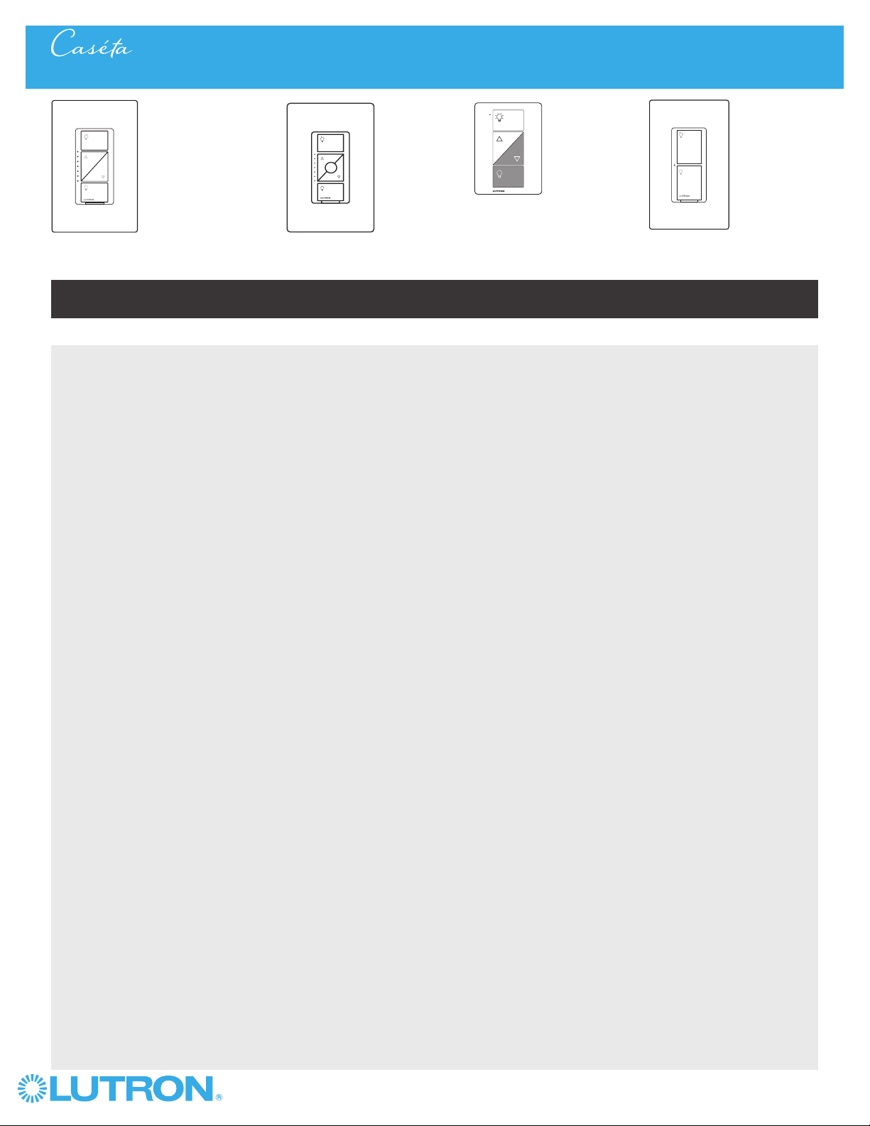
In-wall dimmer & PRO dimmer
PD-6WCL / PD-10NXD
Plug-in lamp dimmer
PD-3PCL
ELV+ Dimmer
PD-5NE
Thank you for purchasing CasétaR Wireless from Lutron. This document will guide you through several additional
installation topics beyond those covered in the quick-start guide included with your product.
Table of Contents
In-wall switch
PD-5WS-DV / PD-6ANS
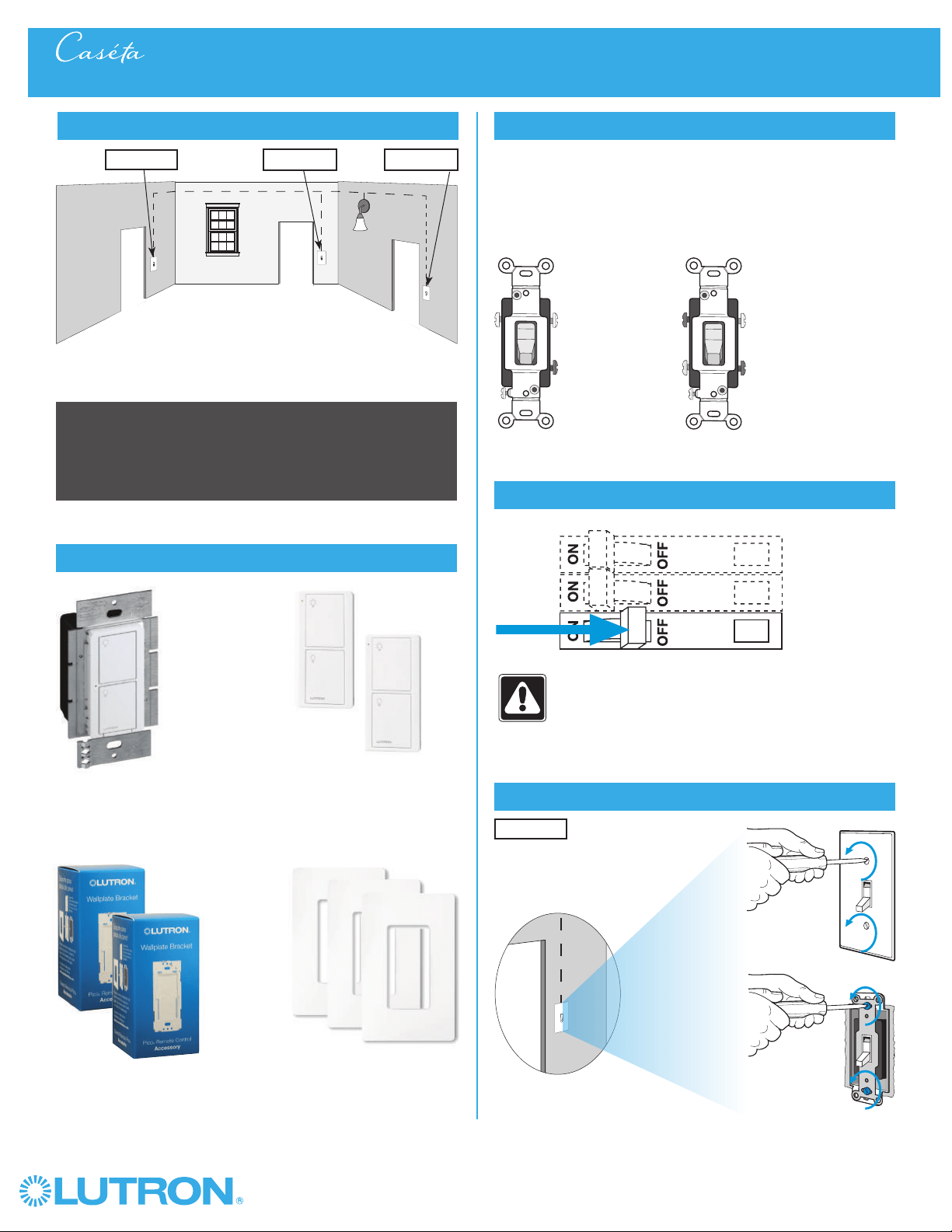
3-Way Installation - If you have two switches controlling your lights, follow this procedure to install your in-wall dimmer or switch
With a PicoR Remote Control
In-Wall Dimmer with PicoR Remote Control: ................................................................................................................. Page 2 - 5
In-Wall Switch with PicoR Remote Control: ................................................................................................................... Page 6 - 9
In-Wall PRO Dimmer with PicoR Remote Control: ........................................................................................................ Page 10 - 13
In-Wall Neutral Switch with PicoR Remote Control: ..................................................................................................... Page 14 - 17
In-Wall ELV+ Dimmer with PicoR Remote Control: ....................................................................................................... Page 18 - 21
With a Mechanical Toggle Switch
In-Wall Switch with Mechanical Toggle Switch: ........................................................................................................... Page 22 - 24
In-Wall PRO dimmer with Mechanical Toggle Switch: ................................................................................................. Page 25 - 27
In-Wall Neutral Switch with Mechanical Toggle Switch: ............................................................................................. Page 28 - 30
Multi-Location Installation - If you have three or more switches controlling your lights, follow this procedure to
install your in-wall dimmer or switch
In-Wall Dimmer with PicoR Remote Controls: ................................................................................................................ Page 31 - 35
In-Wall PRO Dimmer with PicoR Remote Controls: ...................................................................................................... Page 36 - 40
In-Wall Switch with PicoR Remote Controls: ................................................................................................................. Page 41 - 45
In-Wall Neutral Switch with PicoR Remote Controls: ................................................................................................... Page 46 - 50
In-Wall ELV+ Dimmer with PicoR Remote Controls: ...................................................................................................... Page 51 - 55
Adjusting the Low-End Trim - Follow this procedure if you experience performance issues such as flickering,
flashing or other abnormal light behavior when your dimmer is at a low light level
On an In-Wall Dimmer: .............................................................................................................................................................Page 56
On an In-Wall PRO Dimmer: ..................................................................................................................................................Page 58
On an In-Wall ELV+ Dimmer: .................................................................................................................................................. Page 59
On a Plug-In Lamp Dimmer: ........................................................................................................................................... Page 62
Adjusting the High-End Trim - Follow this procedure to adjust the maximum light output allowed by your
in-wall dimmer
On an In-Wall Dimmer: ...................................................................................................................................................... Page 57
On an In-Wall PRO Dimmer: ............................................................................................................................................ Page 60
On an In-Wall ELV+ Dimmer: ............................................................................................................................................ Page 61
On a Plug-In Lamp Dimmer: ............................................................................................................................................ Page 63
Converting a Plug-In Lamp Dimmer to a Switch to Control Non-Dim Loads (Lights Only)
Follow this procedure if you would like your plug-in lamp dimmer to act as a switch for non-dimmable lighting loads ...... Page 64
Setting Dimmer Phase on a CasétaR Wireless In-Wall ELV+ Dimmer .......................................................... Page 65
Removing Paired PicoR Remote Controls - Follow this procedure if you need to remove paired Pico®
remote controls or reset your dimmer or switch to its factory
default settings
From a Dimmer: ................................................................................................................................................................ Page 66
From an In-Wall Switch: .................................................................................................................................................. Page 67
From a LutronR Shade: ..................................................................................................................................................... Page 68-69
Changing the Favorite Light Level on a Pico® Remote Control - Follow this procedure to change the
light level your dimmer recalls when you press the "Favorite" button on your PicoR remote control ..................................... Page 70
Changing the Favorite Light Level on an ELV+ Dimmer - Follow this procedure to change the
light level your dimmer recalls when you press the "Favorite" button on your Phase Selectable Dimmer ............................. Page 71
Installing a LUT-MLC Load Adapter with an In-Wall Switch - The LUT-MLC is provided to help ensure
proper operation of the CasétaR Wireless switch with LED, fluorescent, and ELV lighting loads ........................................... Page 72
Troubleshooting ................................................................................................................................................................ Page 73
2
Wireless
®
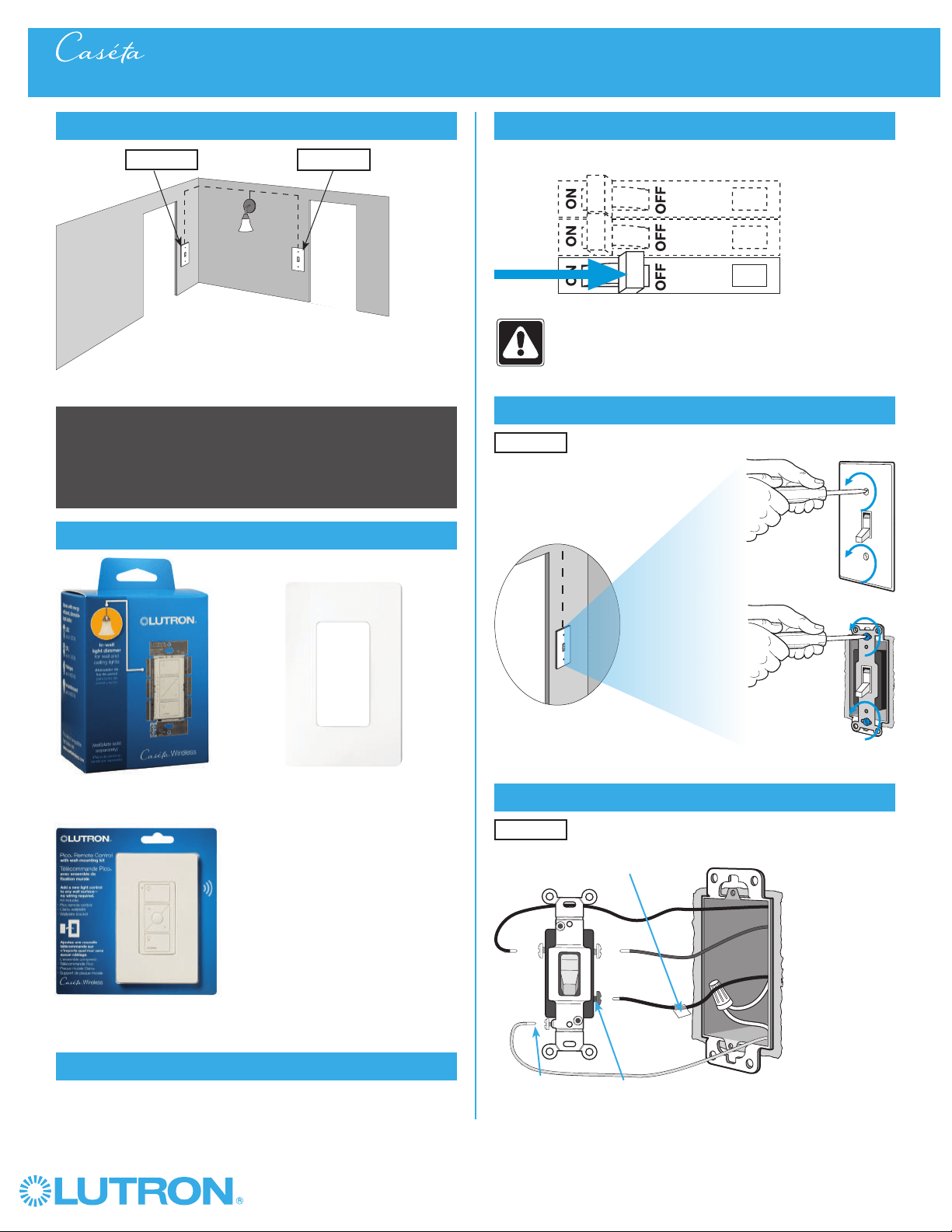
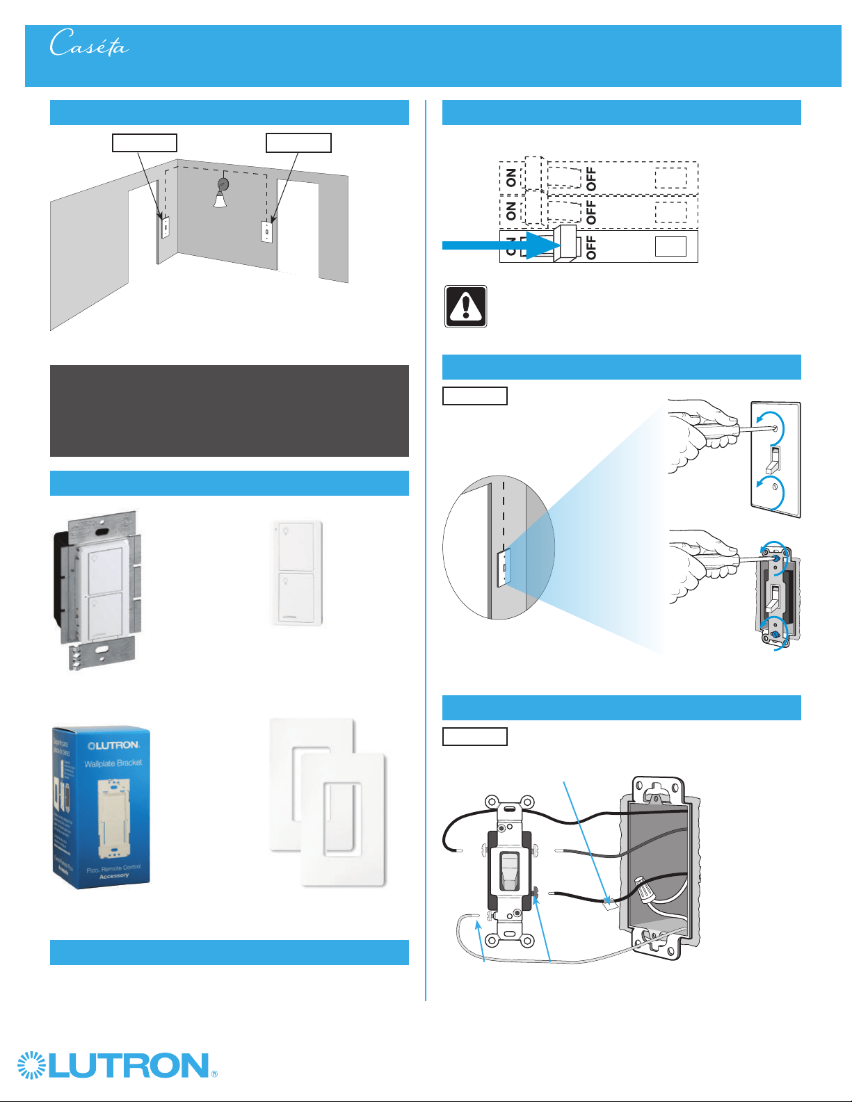
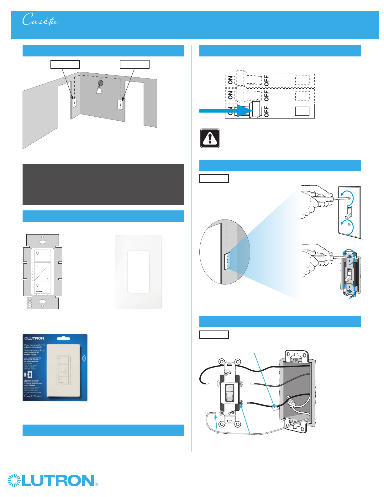
1
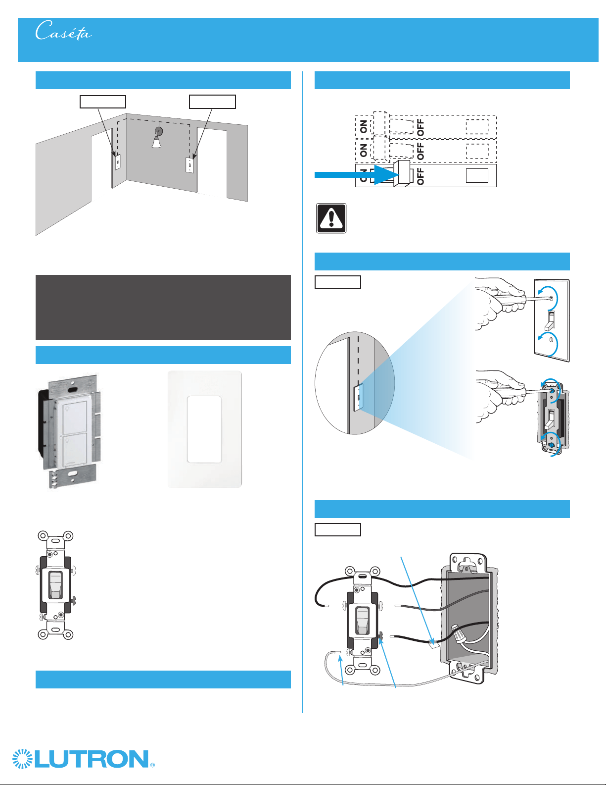
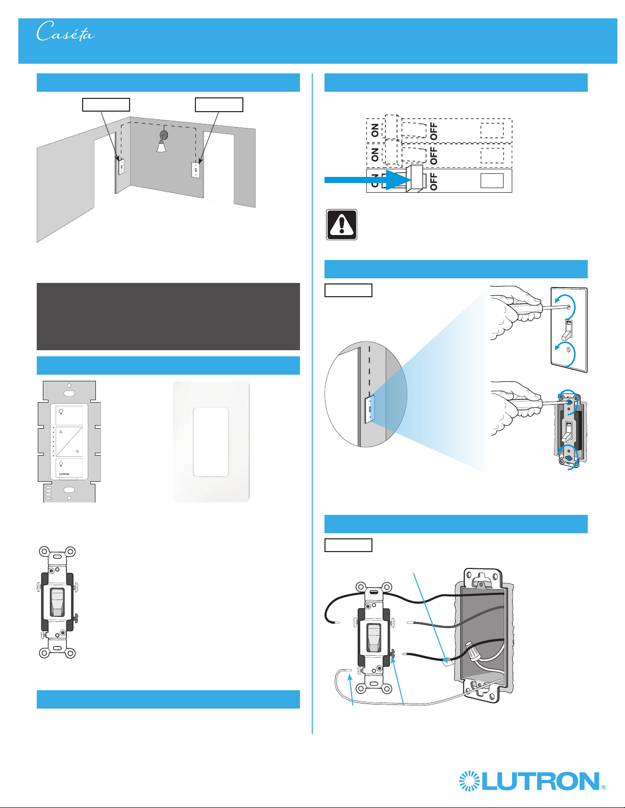
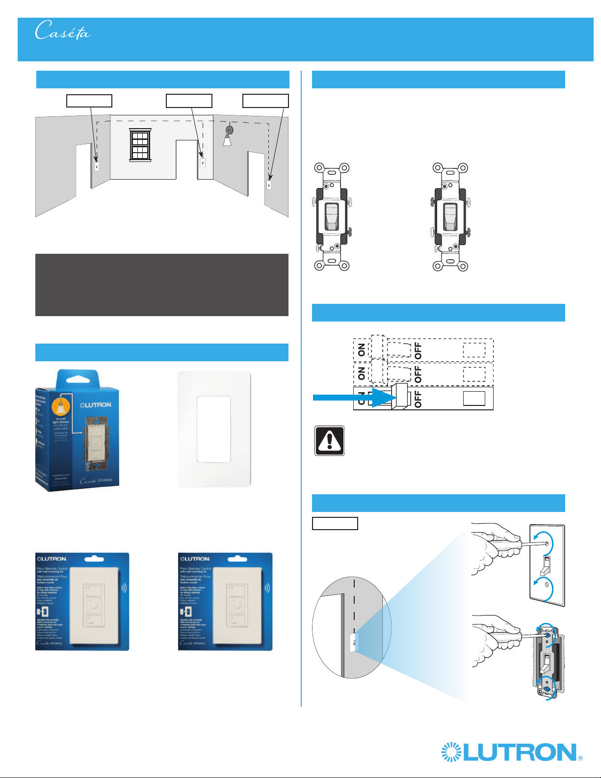
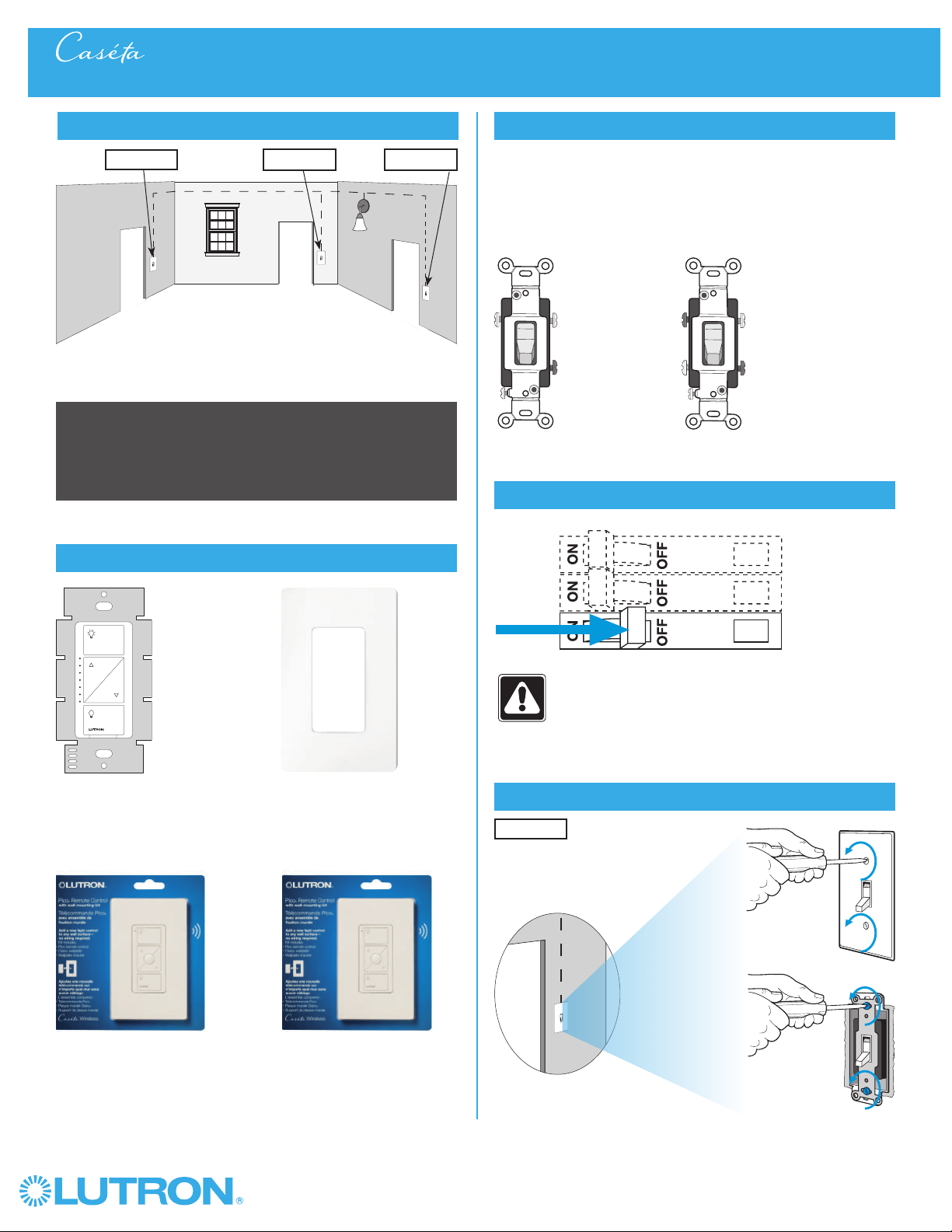
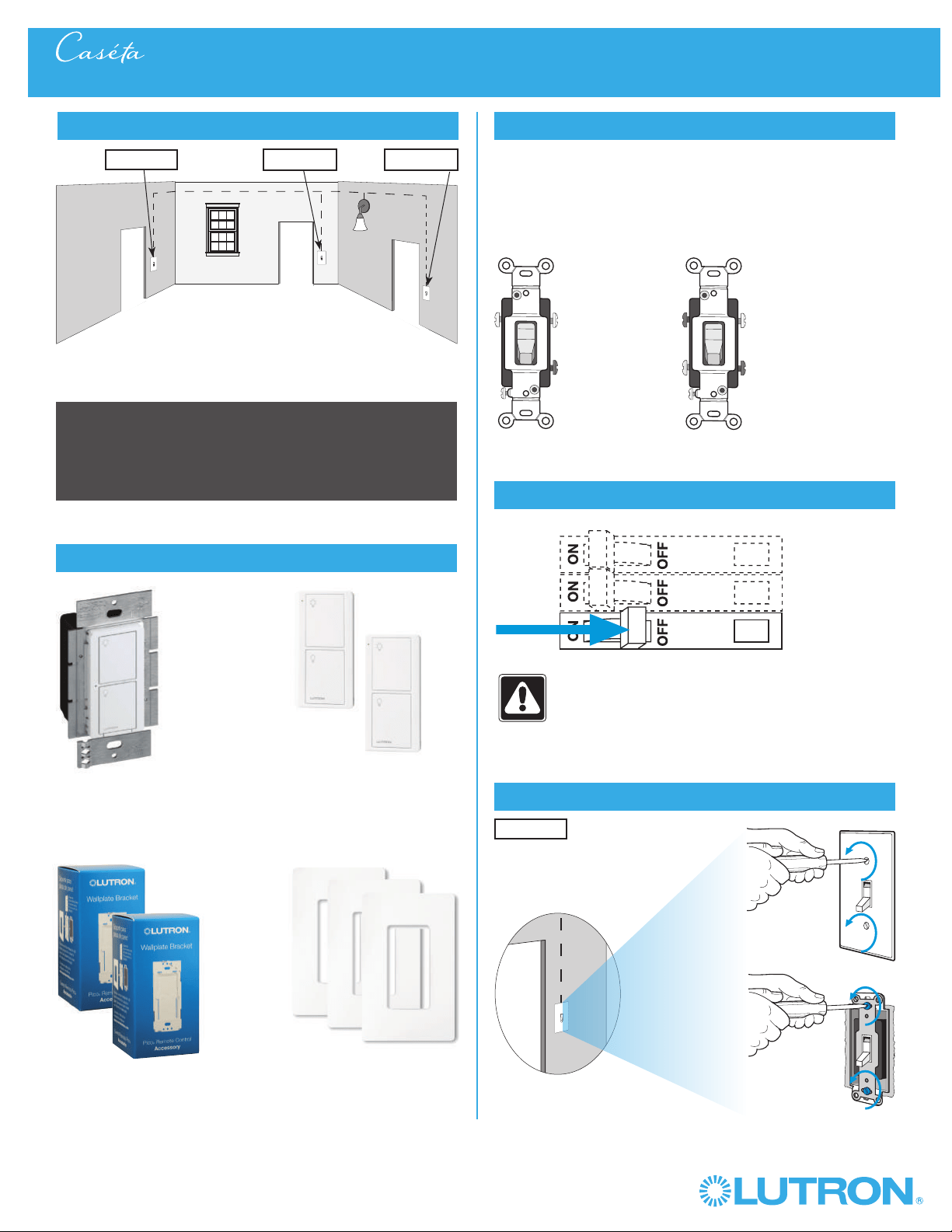
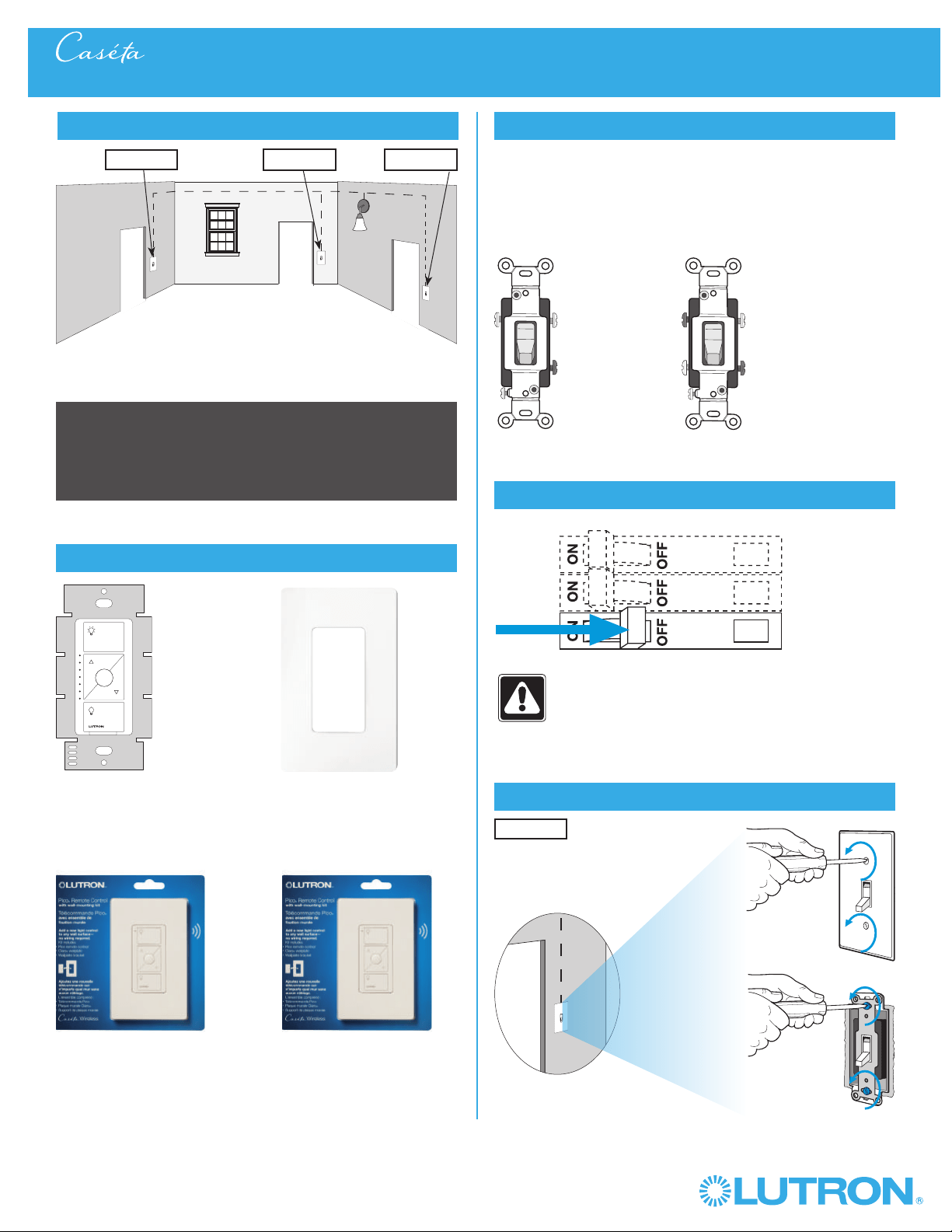
Identify existing wiring
Two switches control the lights (3-way installation)
2
What you need for a 3-way installation
+
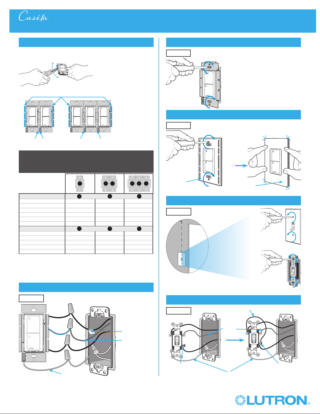
WARNING! Shock Hazard. May result in serious
injury or death. Turn off power at circuit breaker
before installing the unit.
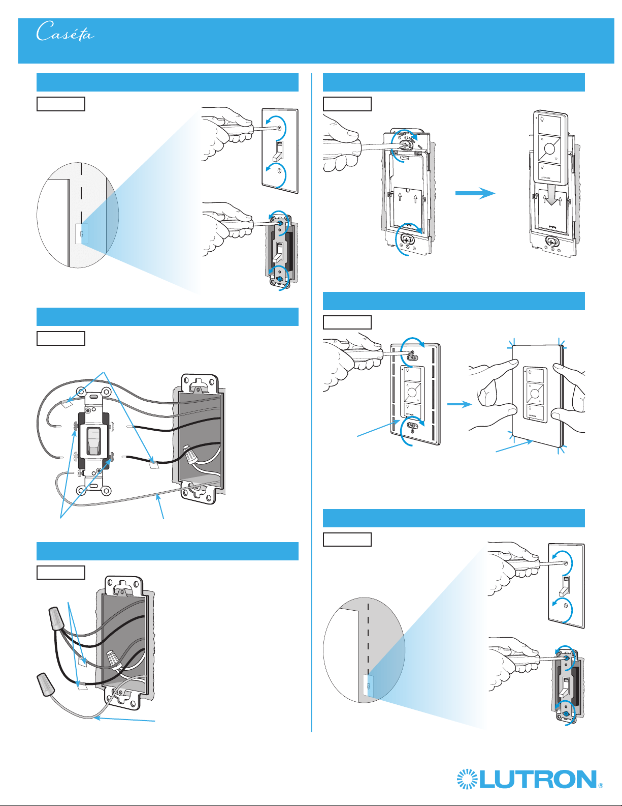
4
Turn power off at circuit breaker
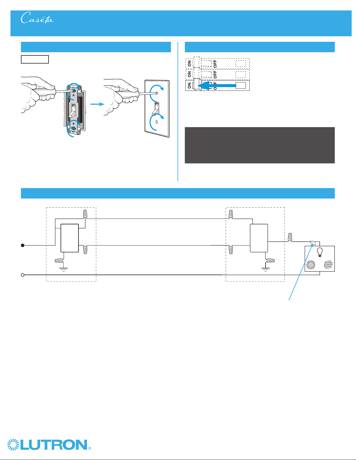
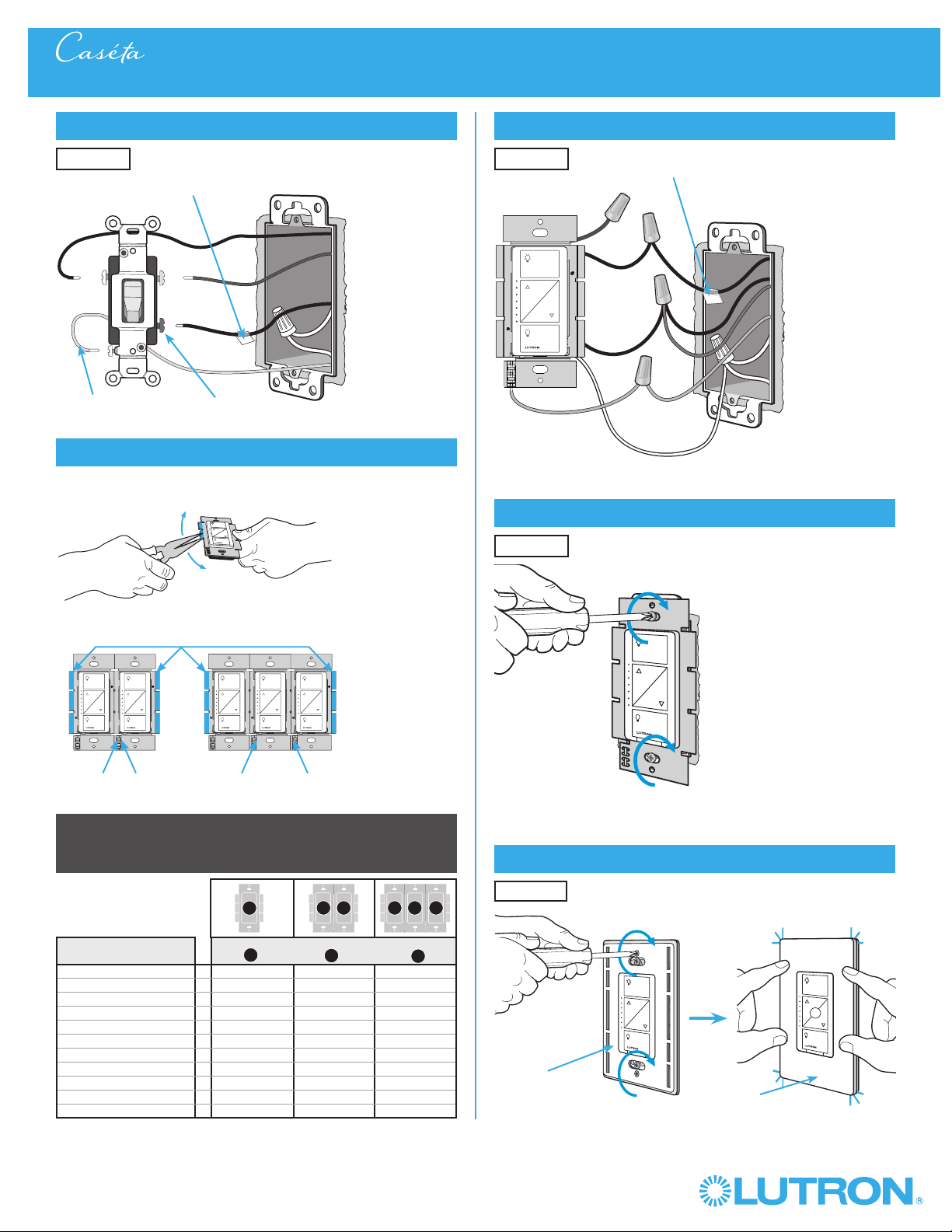
5
Remove existing switch from wall
6
Tag and disconnect wires from the existing switch
Place tag - to identify wire on
different color screw
Different
Color
Screw
Ground
(Green /
Bare Copper)
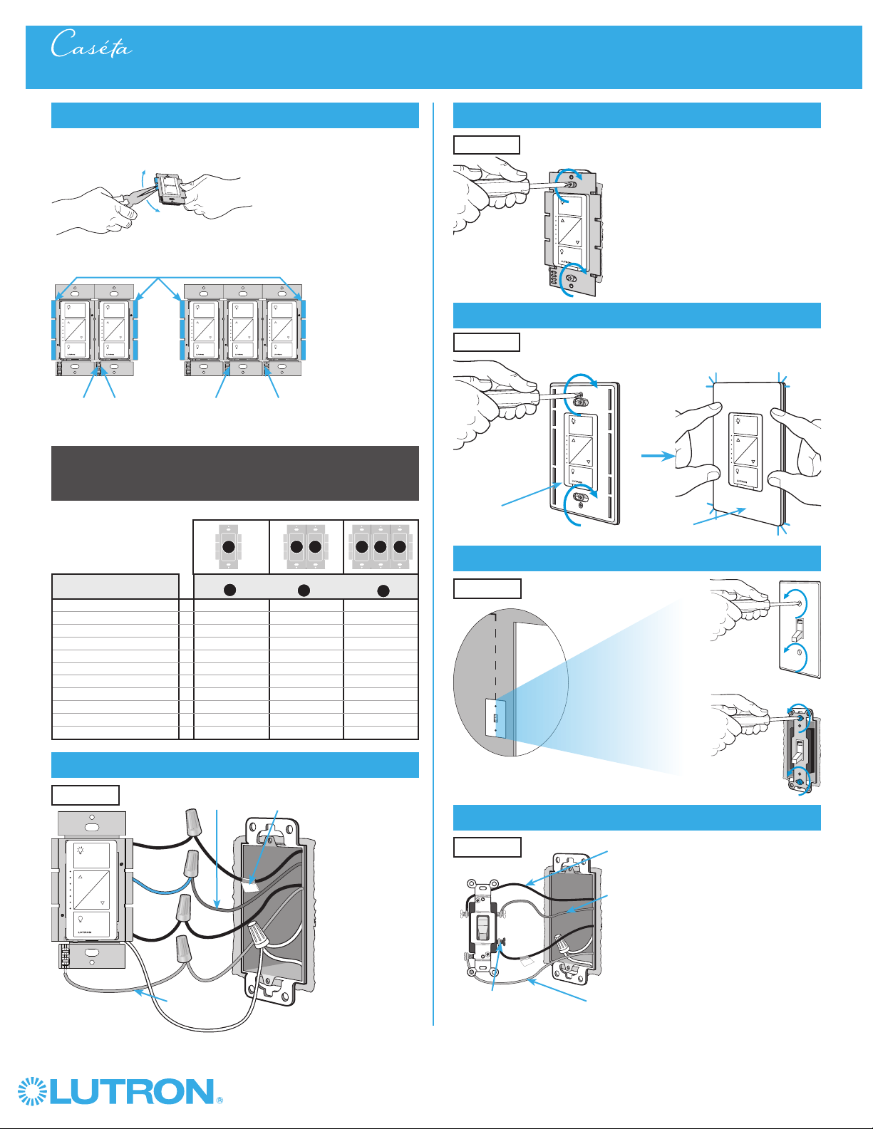
3-Way Installation - CasétaR Wireless In-Wall Dimmer with PicoR Remote Control
Location 1 Location 2
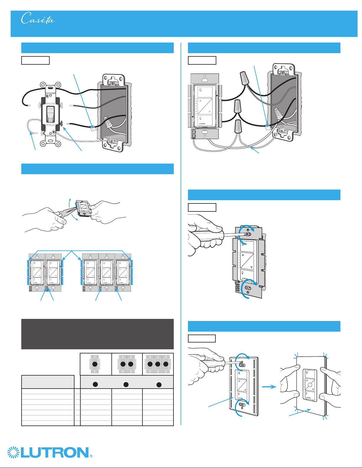
In-wall dimmer
PD-6WCL
Pico® remote control
with wall-mounting kit
PJ2-WALL
- If one switch controls the lights (single-pole installation)
See quick-start guide that came with your dimmer
- If three or more switches control the lights
(multi-location installation) See page 31 for details
Important note:
3
Choose a location for your CasétaR Wireless dimmer
Choose which location you want the CasétaR Wireless dimmer installed in.
This will be Location 1.
Location 1
Location 1
ClaroR Wallplate
CW-1
+

3
Wireless
®
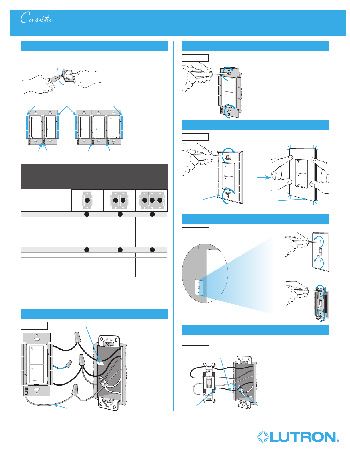
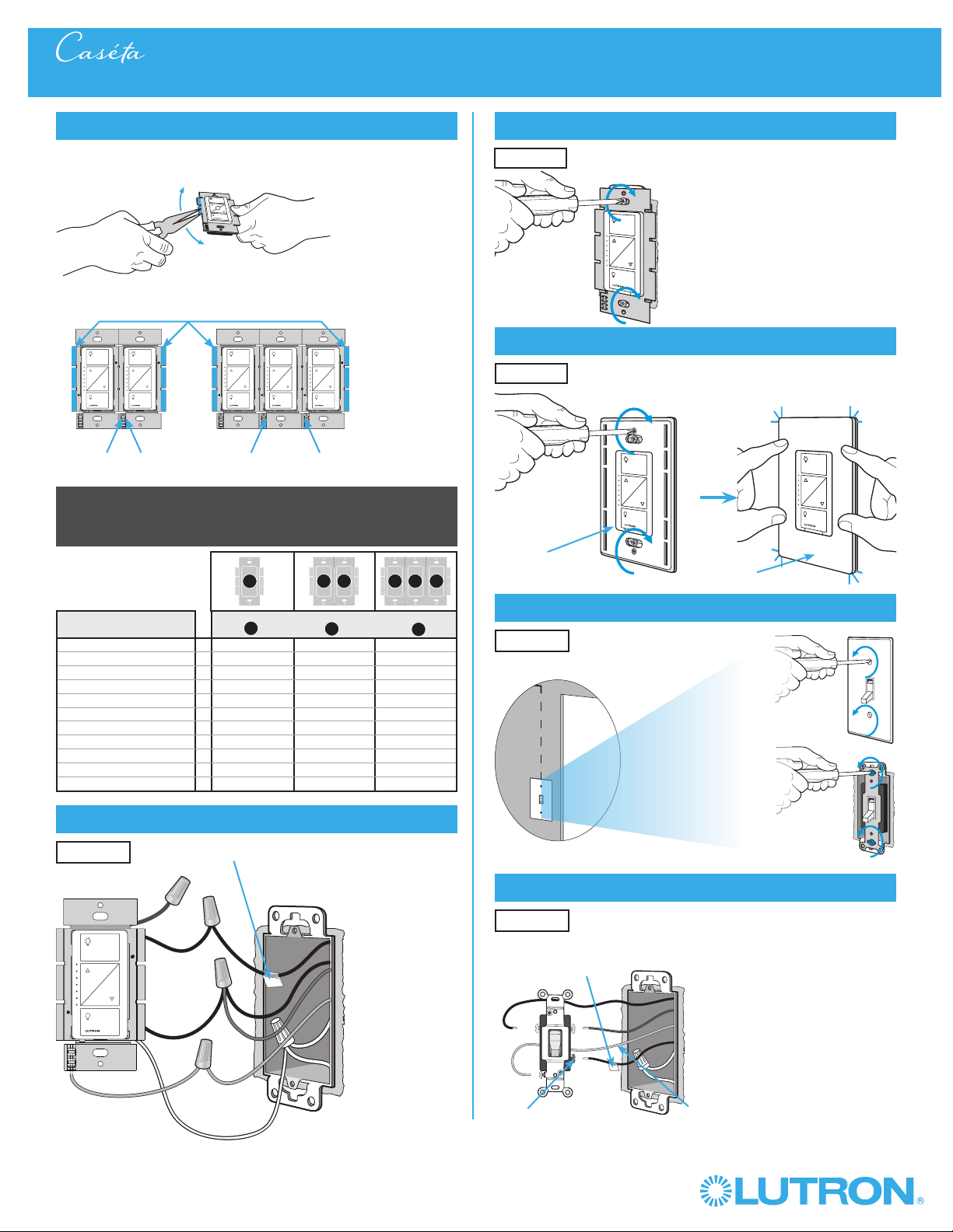
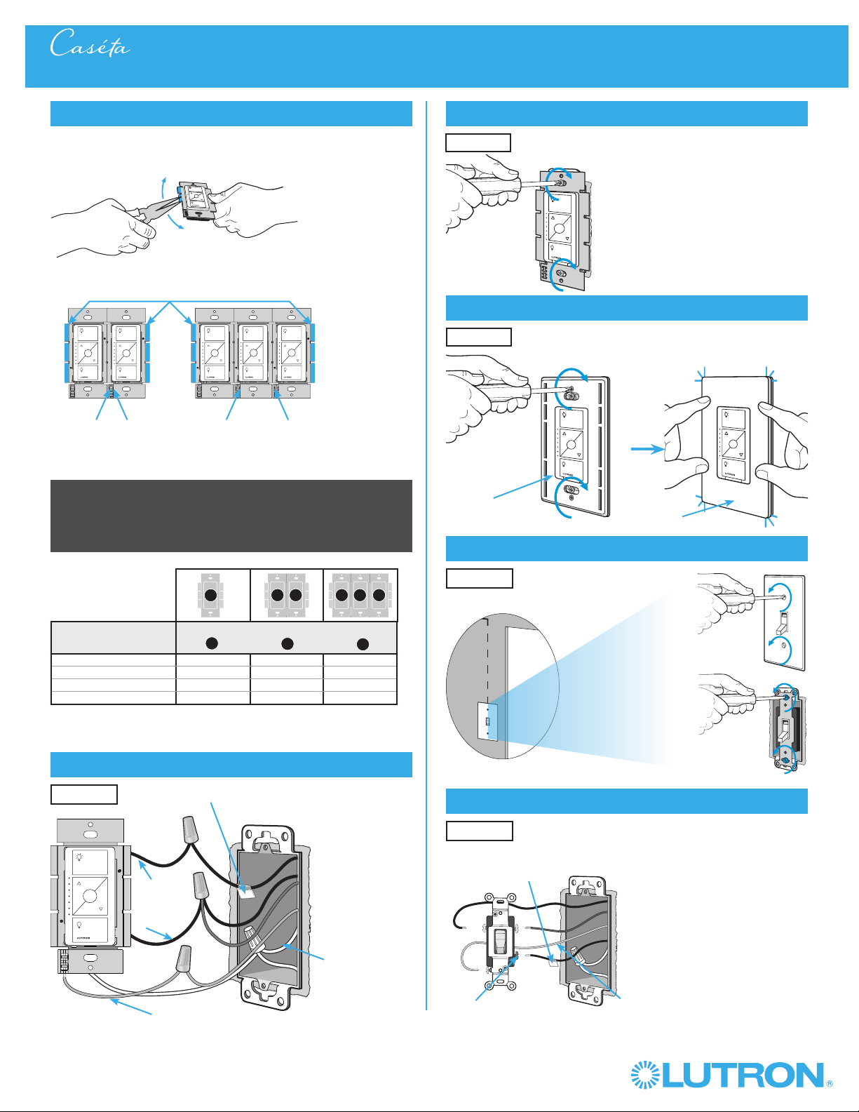
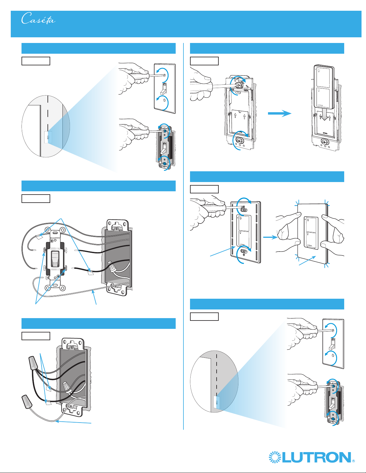
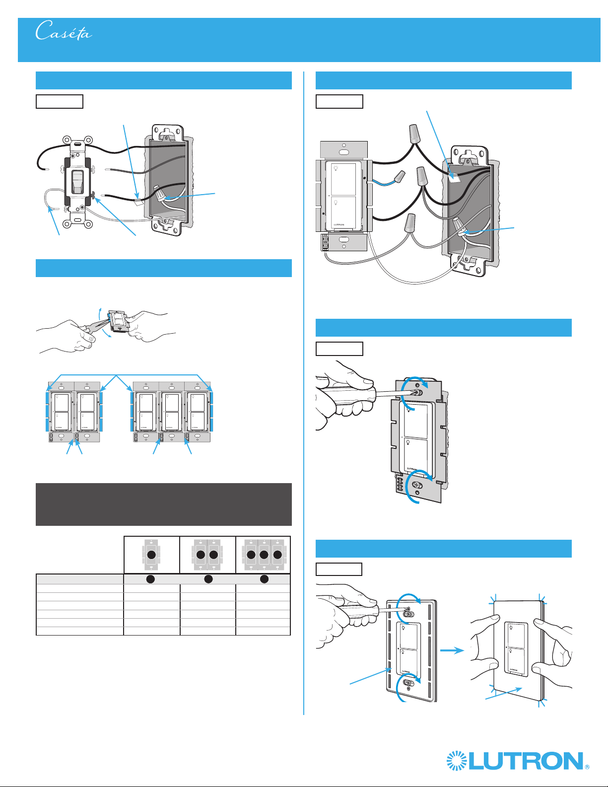
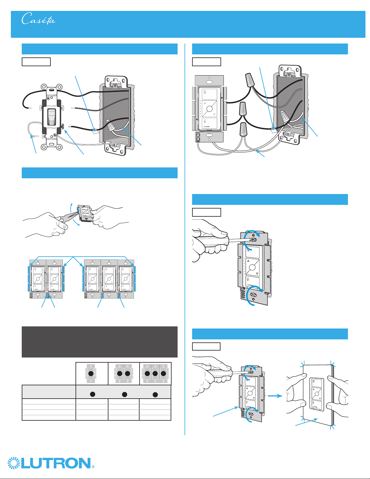
7
Remove side sections (if necessary)
Do not remove outside side sections
on dimmers at the end of gang.
Each dimmer has inside
side sections removed.
Dimmer in the middle
has all side sections
removed.
Total Dimmable LED Wattage
Incandescent/Halogen Total Wattage
0 W + 600 W 500 W 400 W
1 W – 25 W + 500 W 400 W 300 W
26 W – 50 W + 400 W 300 W 200 W
51 W – 75 W + 300 W 200 W 100 W
76 W – 100 W + 200 W 100 W 50 W
101 W – 125 W + 100 W 50 W 0 W
126 W – 150 W + 0 W 0 W 0 W
A
B
C
B
B B
C
B
A
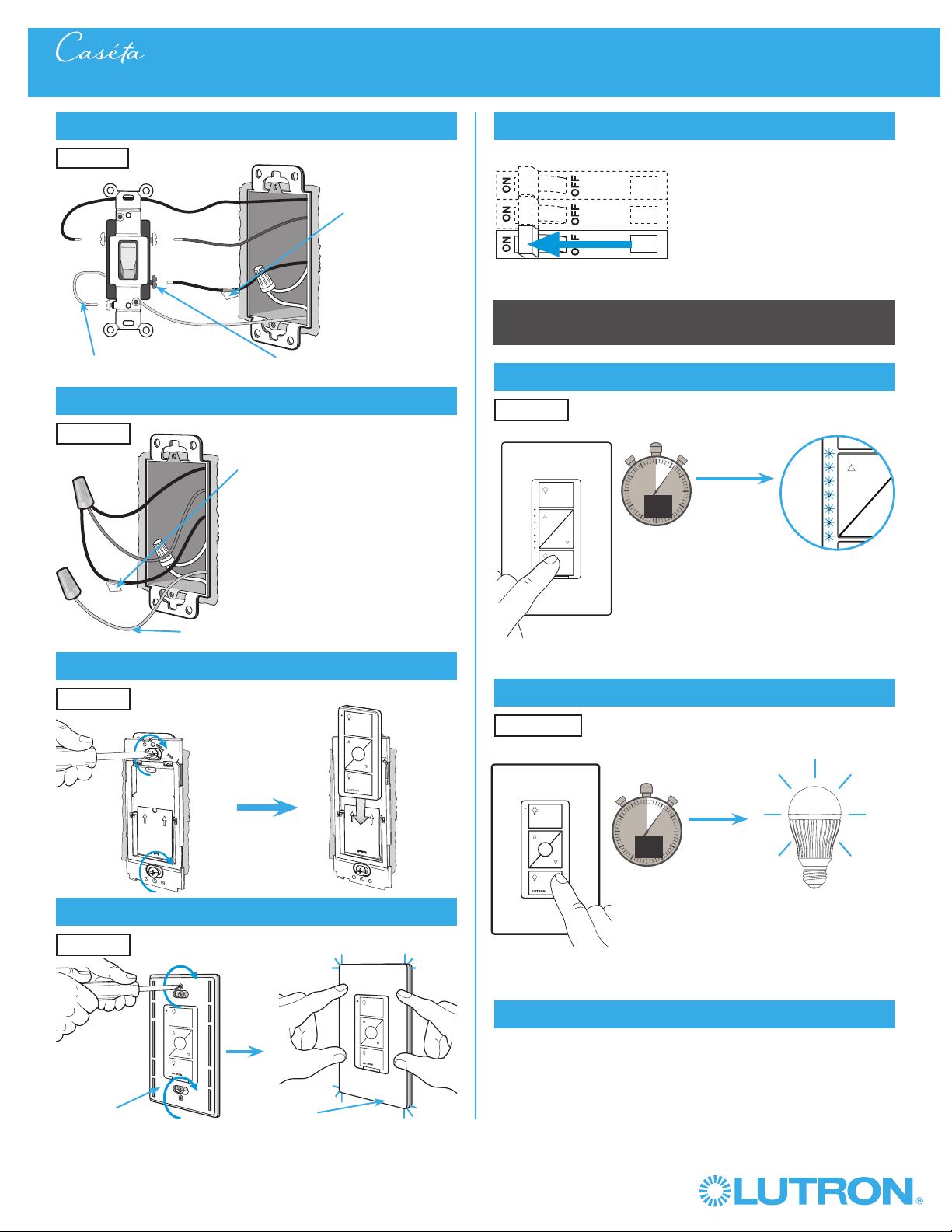
8
Connect the CasétaR Wireless dimmer
Tagged Wire
Ground
(Green Wire)
9
Mount the CasétaR Wireless dimmer
10
Attach the wallplate
‘snap’
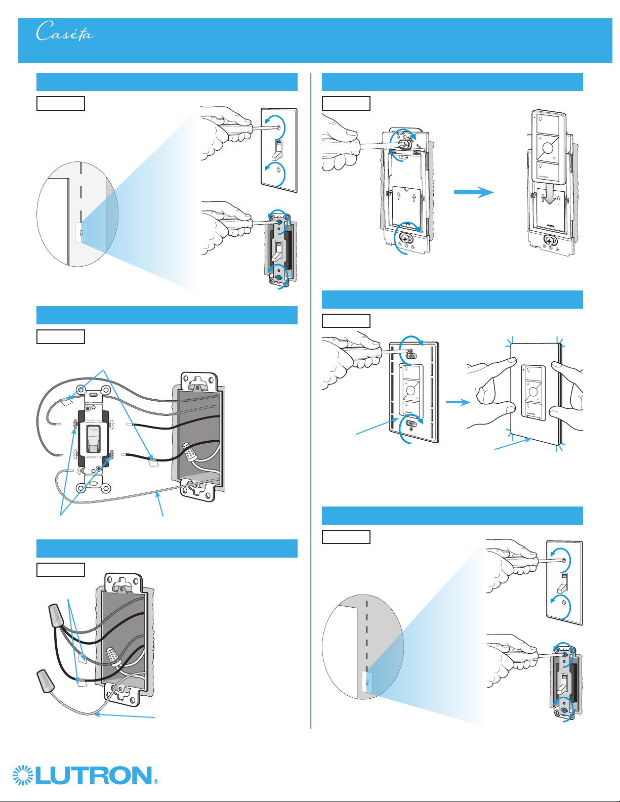
11
Remove existing switch from wall at Location 2
3-Way Installation - CasétaR Wireless In-Wall Dimmer with PicoR Remote Control
12
Tag and disconnect wires from the switch
Ground (Green / Bare Copper)
Different
Color
Screw
Important note:
Removing side sections reduces the dimmer’s maximum wattage
rating. See the chart below for maximum wattage information.
When installing more than one CasétaR Wireless dimmer in the same
wallbox, it is necessary to remove inner side sections prior to wiring. See
image and chart below for more information.
Wallplate
Adapter
Wallplate
Location 1
Location 1
Location 2
Place tag - to identify wire on
different color screw
Location 2
Location 1

4
Wireless
®
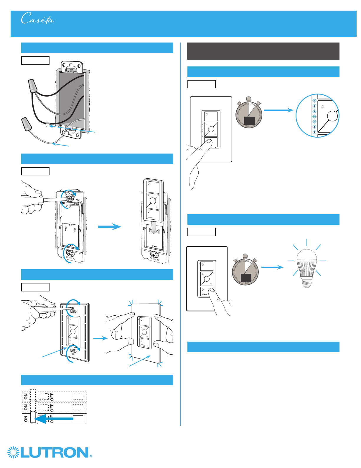
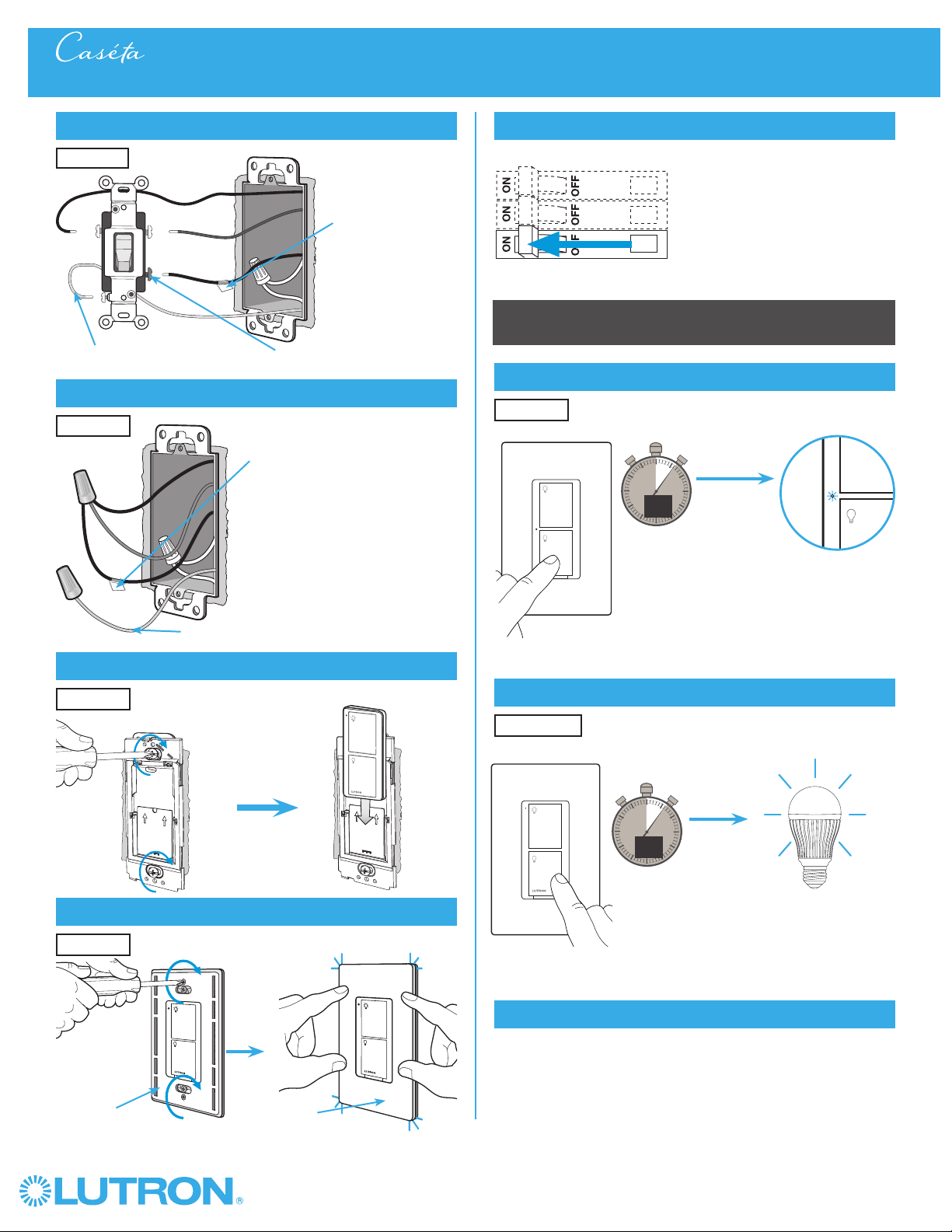
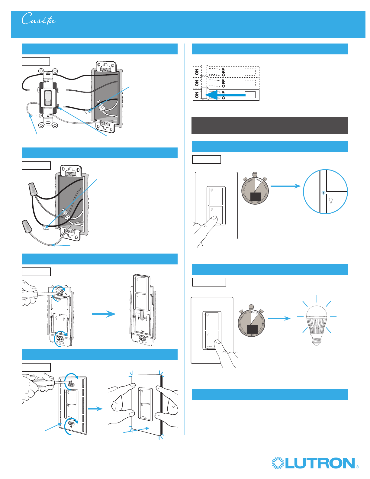
13
Connect the wires
Ground
14
Attach the wallplate bracket and PicoR remote control
15
Attach the wallplate
‘snap’
16
Turn power on at circuit breaker
3-Way Installation - CasétaR Wireless In-Wall Dimmer with PicoR Remote Control
Pairing the dimmer and PicoR remote control
17
Press and hold "Off" button on dimmer
0
5
10
15
6
sec.
UNTIL
HOLD
Status LEDs flash
18
Press and hold "Off" button on remote control
Lights flash
three times
0
5
10
15
6
sec.
UNTIL
Wallplate
Adapter
Wallplate
Location 2
Tagged Wire
Location 2
Location 2
Location 2
Location 1
Repeat steps 17 and 18 to pair additional
remote controls.
19
Pair additional remote controls
HOLD
3x
5
Wireless
®
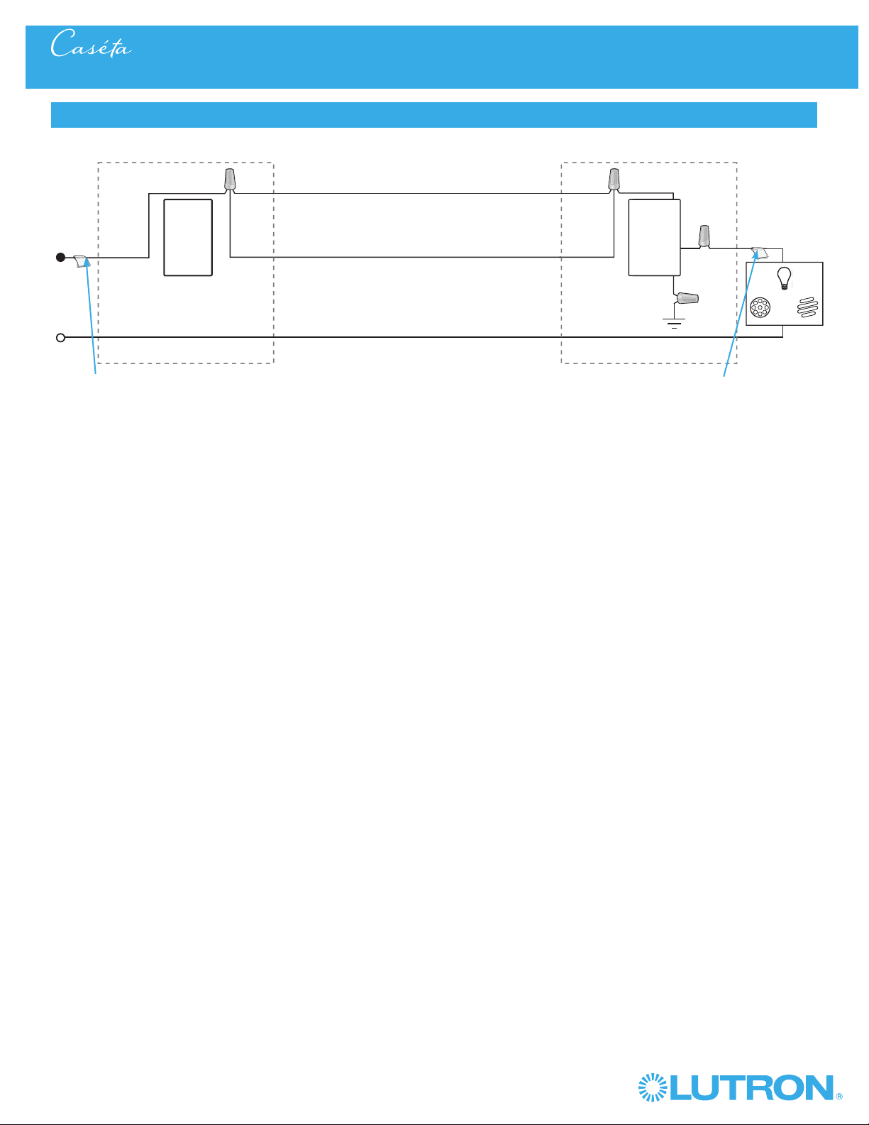
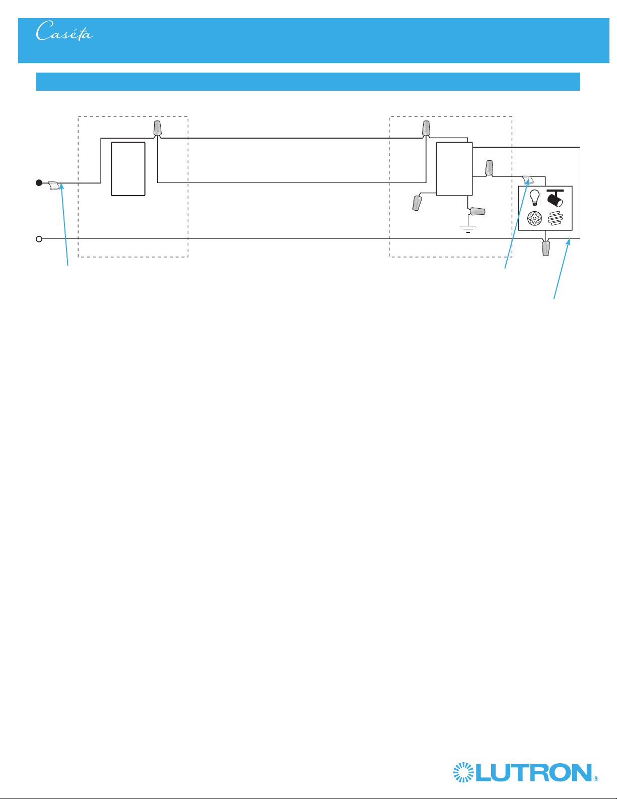
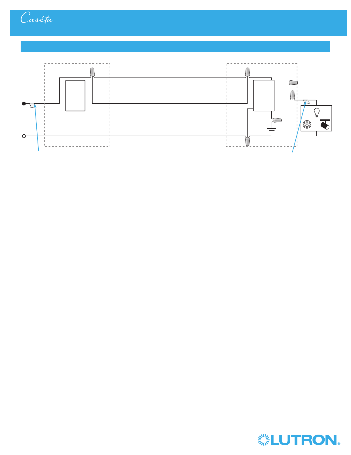
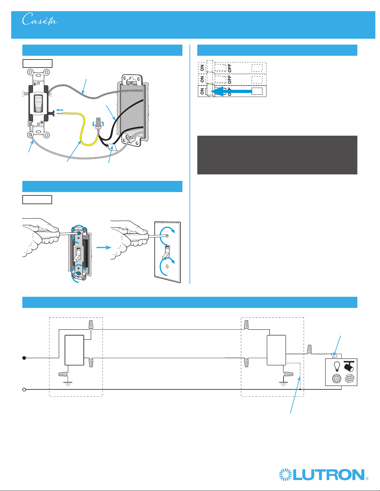
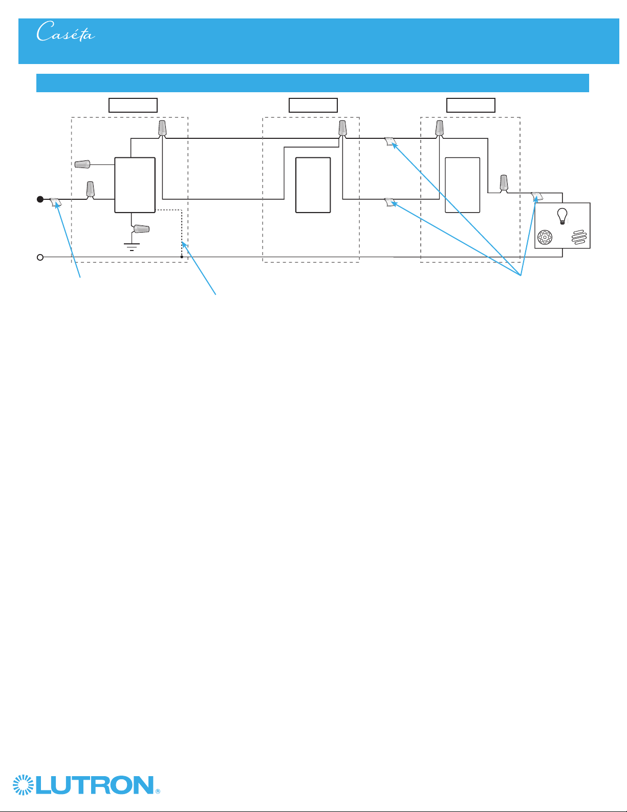
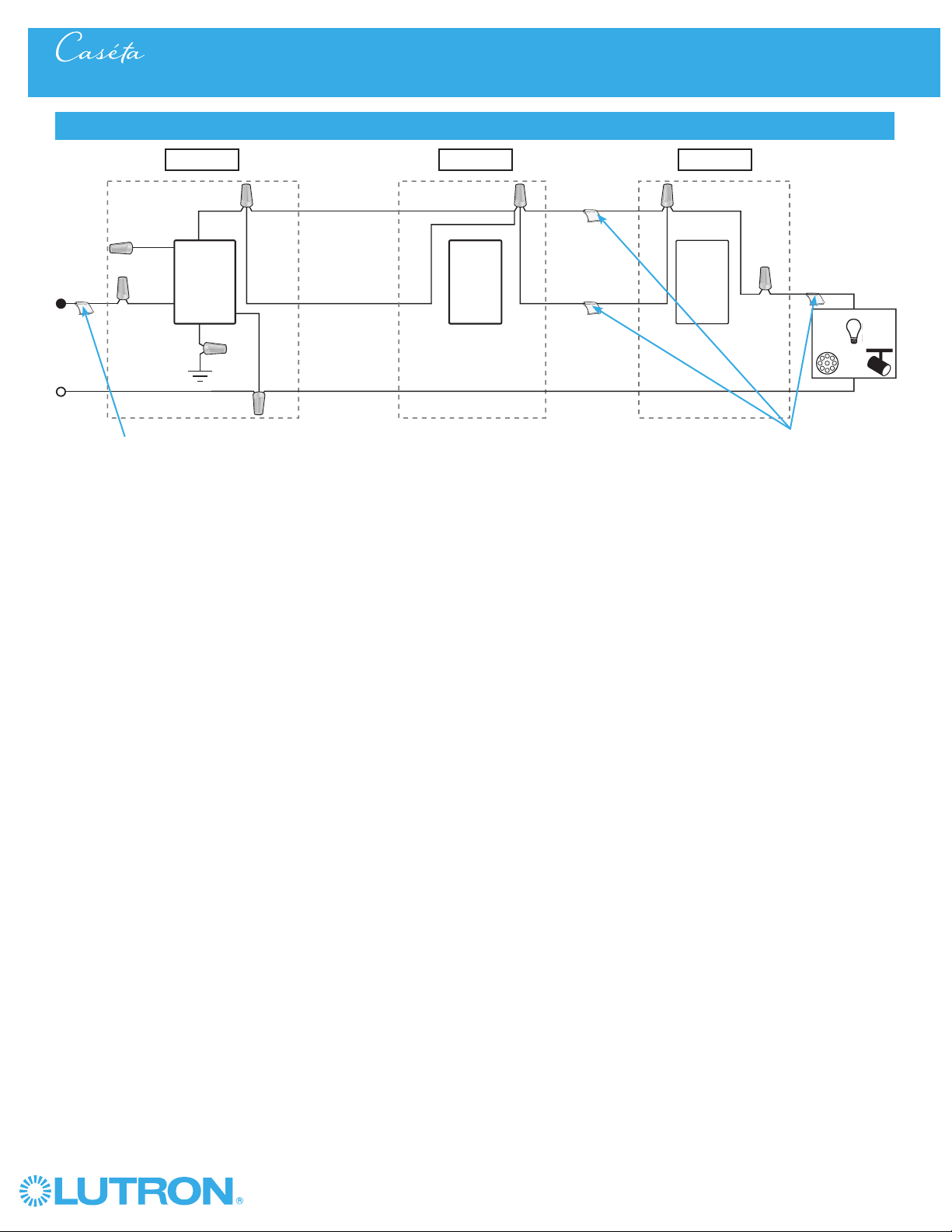
3-Way Installation - CasétaR Wireless In-Wall Dimmer with PicoR Remote Control
Neutral
PicoR
Remote
Control
Line / Hot
Traveler
CasétaR
Wireless
Dimmer *
Ground
Load
LED
DEL
LFC
A
CFL
AFC
INC /
HAL
Schematic Diagram
Traveler
* Dimmer may be installed in either location.
Tagged Wire
Tagged Wire
6
Wireless
®
1
Identify existing wiring
Two switches control the lights (3-way installation)
2
What you need for a 3-way installation
WARNING! Shock Hazard. May result in serious
injury or death. Turn off power at circuit breaker
before installing the unit.
4
Turn power off at circuit breaker
5
Remove existing switch from wall
6
Tag and disconnect wires from the existing switch
Place tag - to identify wire on
different color screw
Different
Color
Screw
Ground
(Green /
Bare Copper)
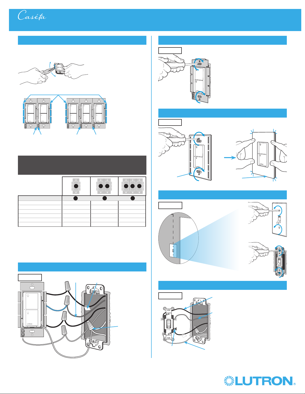
3-Way Installation - CasétaR Wireless In-Wall Switch with PicoR Remote Control
Location 1 Location 2
- If one switch controls the lights (single-pole installation)
See quick-start guide that came with your switch
- If three or more switches control the lights
(multi-location installation) See page 41 for details
Important note:
3
Choose a location for your CasétaR Wireless switch
Choose which location you want the CasétaR Wireless switch installed in.
This will be Location 1.
Location 1
Location 1
+
In-wall switch
PD-5WS-DV
PicoR remote control
PJ2-2B
+
Wallplate Bracket
PICO-WBX-ADAPT
+
Two ClaroR Wallplates
CW-1
7
Wireless
®
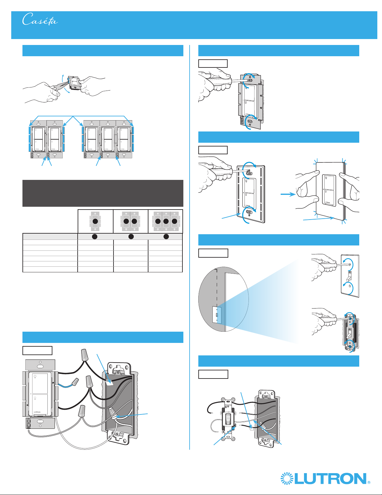
7
Remove side sections (if necessary)
Do not remove outside side sections
on switches at the end of gang.
Each switch has inside
side sections removed.
Switch in the middle has
all side sections removed.
8
Connect the new Caséta® Wireless switch
Tagged Wire
Ground
(Green Wire)
9
Mount the Caséta® Wireless switch
10
Attach the wallplate
‘snap’
11
Remove existing switch from wall at Location 2
3-Way Installation - Caséta® Wireless In-Wall Switch with Pico® Remote Control
12
Tag and disconnect wires from the existing switch
Ground (Green / Bare Copper)
Different
Color
Screw
When installing more than one Caséta
® Wireless switch in the same wallbox,
it is necessary to remove inner side sections prior to wiring. See image and
chart below for more information.
Wallplate
Adapter
Wallplate
Location 1
Location 1
Location 2
Place tag - to identify wire on
different color screw
Location 2
Location 1
Important note:
Removing side sections reduces the switch’s maximum wattage
rating. See the chart below for maximum wattage information.
B
B B
C
B
A
PD-5WS-DV (120 V~)
LED 5 A 4 A 3 A
Halogen / incandescent 600 W 450 W 350 W
Electronic Low-Voltage 600 W 450 W 350 W
Magnetic Low-Voltage
1
600 VA / 475 W 450 VA / 350 W 350 VA / 275 W
Fluorescent
2
5 A 4 A 3 A
General Purpose Fan 3 A 3 A 3 A
PD-5WS-DV ( 277 V~)
LED 5 A 4 A 3 A
Halogen / incandescent 1350 W 1100 W 800 W
Electronic Low-Voltage 1350 W 1100 W 800 W
Magnetic Low-Voltage
1
1350 VA / 1075 W 1100 VA / 875 W 800 VA / 625 W
Fluorescent
2
5 A 4 A 3 A
A
B C
A
B C
1
The maximum lamp wattage is determined by the efficiency of the transformer, with
70% – 85% as typical. For actual transformer efficiency, contact either the fixture or
transformer manufacturer. The total VA rating of the transformer(s) shall not exceed the VA
rating of the in-wall switch.
2
The in-wall switch is ULR Listed for use with all magnetic and electronic fluorescent ballasts.
Black
Blue
Black

8
Wireless
®
13
Connect the wires
Ground
14
Attach the wallplate bracket and Pico® remote control
15
Attach the wallplate
‘snap’
16
Turn power on at circuit breaker
3-Way Installation - Caséta® Wireless In-Wall Switch with Pico® Remote Control
Pairing the switch and PicoR remote control
17
Press and hold "Off" button on switch
0
5
10
15
6
sec.
UNTIL
HOLD
Status LED flashes
18
Press and hold "Off" button on remote control
Lights flash
three times
0
5
10
15
6
sec.
UNTIL
Wallplate
Adapter
Wallplate
Location 2
Tagged Wire
Location 2
Location 2
Location 2
Location 1
Repeat steps 17 and 18 to pair additional
remote controls.
19
Pair additional remote controls
HOLD
3x

9
Wireless
®
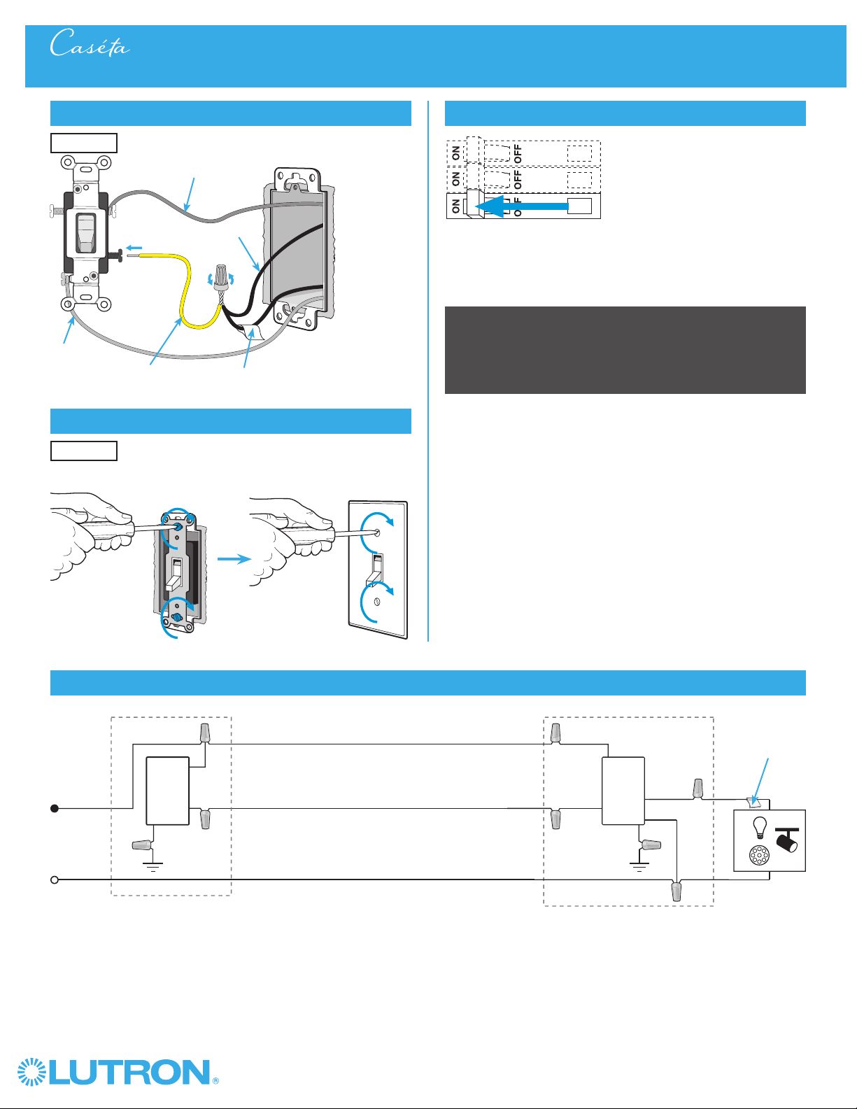
3-Way Installation - Caséta® Wireless In-Wall Switch with Pico® Remote Control
Neutral
Pico
®
Remote
Control
Line / Hot
Traveler
Caséta®
Wireless
Switch *
Ground
(Green)
Load
LED
DEL
LFC
A
CFL
AFC
INC /
HAL
Schematic Diagram
Traveler
* Switch may be installed in either location.
Tagged Wire
Tagged Wire
Black
Blue
Black
10
Wireless
®
1
Identify existing wiring
Two switches control the lights (3-way installation)
2
What you need for a 3-way installation
+
WARNING! Shock Hazard. May result in serious
injury or death. Turn off power at circuit breaker
before installing the unit.
4
Turn power off at circuit breaker
5
Remove existing switch from wall
6
Tag and disconnect wires from the existing switch
Place tag - to identify wire on
different color screw
Different
Color
Screw
Ground
(Green /
Bare Copper)
3-Way Installation - Caséta® Wireless In-Wall PRO Dimmer with Pico® Remote Control
Location 1 Location 2
In-wall PRO dimmer
PD-10NXD
Pico® remote control
with wall-mounting kit
PJ2-WALL
- If one switch controls the lights (single-pole installation)
See quick-start guide that came with your dimmer
- If three or more switches control the lights
(multi-location installation) See page 36 for details
Important note:
3
Choose a location for your Caséta® Wireless dimmer
Choose which location you want the Caséta® Wireless dimmer installed in.
This will be Location 1.
Location 1
Location 1
Claro® Wallplate
CW-1
+
11
Wireless
®
7
Remove side sections (if necessary)
Do not remove outside side sections
on dimmers at the end of gang.
Each dimmer has inside
side sections removed.
Dimmer in the middle has all
side sections removed.
Total Dimmable LED Wattage Incandescent/Halogen Total Wattage
0 W + 1000 W 800 W 600 W
1 W – 25 W + 900 W 750 W 550 W
26 W – 50 W + 800 W 700 W 500 W
51 W – 75 W + 700 W 600 W 450 W
76 W – 100 W + 600 W 500 W 400 W
101 W – 125 W + 500 W 400 W 300 W
126 W – 150 W + 400 W 300 W 200 W
151 W – 175 W + 300 W 200 W 100 W
176 W – 200 W + 200 W 100 W 50 W
201 W – 225 W + 100 W 50 W 0 W
226 W – 250 W + 0 W 0 W 0 W
A
B
C
B
B B
C
B
A
8
Connect the Caséta® Wireless dimmer
Tagged Wire
Ground
(Green Wire)
Red
White *
*
If available,
connect the
neutral wire from
the wallbox to the
white wire on the
dimmer. If neutral
is not available,
cap the white
wire with a wire
connector.
Neutral required
for: MLV loads,
LED drivers,
PHPM-PA,
PHPM-3F,
GRX-TVI.
Black
Blue
9
Mount the Caséta® Wireless dimmer
10
Attach the wallplate
‘snap’
11
Remove existing switch from wall at Location 2
3-Way Installation - Caséta® Wireless In-Wall PRO Dimmer with Pico® Remote Control
12
Tag and disconnect wires from the switch
Ground (Green / Bare Copper)
Different
Color
Screw
Important note:
Removing side sections reduces the dimmer’s maximum wattage
rating. See the chart below for maximum wattage information.
When installing more than one Caséta
® Wireless dimmer in the same
wallbox, it is necessary to remove inner side sections prior to wiring. See
image and chart below for more information.
Wallplate
Adapter
Wallplate
Location 1
Location 1
Location 2
Place tag - to identify wire on
different color screw
Location 2
Location 1

12
Wireless
®
13
Connect the wires
Ground
14
Attach the wallplate bracket and Pico® remote control
15
Attach the wallplate
‘snap’
16
Turn power on at circuit breaker
3-Way Installation - Caséta® Wireless In-Wall PRO Dimmer with Pico® Remote Control
Pairing the dimmer and PicoR remote control
17
Press and hold "Off" button on dimmer
0
5
10
15
6
sec.
UNTIL
HOLD
Status LEDs flash
18
Press and hold "Off" button on remote control
Lights flash
three times
0
5
10
15
6
sec.
UNTIL
Wallplate
Adapter
Wallplate
Location 2
Tagged Wire
Location 2
Location 2
Location 2
Location 1
Repeat steps 17 and 18 to pair additional
remote controls.
19
Pair additional remote controls
HOLD
3x
13
Wireless
®
3-Way Installation - Caséta® Wireless In-Wall PRO Dimmer with Pico® Remote Control
Neutral
Pico®
Remote
Control
Line / Hot
Traveler
Caséta®
Wireless
Dimmer *
Ground
Load
LED
DEL
LFC
A
CFL
AFC
INC /
HAL
Schematic Diagram
Traveler
* Dimmer may be installed in either location.
Tagged Wire
Tagged Wire
Black White
(optional)
Red
Blue
If available, connect the neutral wire
from the wallbox to the white wire on the
dimmer. If neutral is not available, cap the
white wire with a wire connector.
Neutral required for: MLV loads, LED
drivers, PHPM-PA, PHPM-3F, GRX-TVI.

14
Wireless
®
1
Identify existing wiring
Two switches control the lights (3-way installation)
2
What you need for a 3-way installation
WARNING! Shock Hazard. May result in serious
injury or death. Turn off power at circuit breaker
before installing the unit.
4
Turn power off at circuit breaker
5
Remove existing switch from wall
6
Tag and disconnect wires from the existing switch
Place tag - to identify wire on
different color screw
Different
Color
Screw
Ground
(Green /
Bare Copper)
3-Way Installation - Caséta® Wireless In-Wall Neutral Switch with Pico® Remote Control
Location 1 Location 2
- If one switch controls the lights (single-pole installation)
See quick-start guide that came with your switch
- If three or more switches control the lights
(multi-location installation) See page 46 for details
Important note:
3
Choose a location for your Caséta® Wireless switch
Choose which location you want the Caséta® Wireless switch installed in.
This will be Location 1.
Location 1
Location 1
+
In-wall switch
PD-6ANS
Pico® remote control
PJ2-2B
+
Wallplate Bracket
PICO-WBX-ADAPT
+
Two Claro® Wallplates
CW-1
Neutral
connection
required
15
Wireless
®
7
Remove side sections (if necessary)
Do not remove outside side sections
on switches at the end of gang.
Each switch has inside
side sections removed.
Switch in the middle has
all side sections removed.
8
Connect the new Caséta® Wireless neutral switch
Tagged Wire
Ground
(Green Wire)
9
Mount the Caséta® Wireless neutral switch
10
Attach the wallplate
‘snap’
11
Remove existing switch from wall at Location 2
3-Way Installation - Caséta® Wireless In-Wall Neutral Switch with Pico® Remote Control
12
Tag and disconnect wires from the existing switch
Ground (Green / Bare Copper)
Different
Color
Screw
When installing more than one Caséta
® Wireless switch in the same wallbox,
it is necessary to remove inner side sections prior to wiring. See image and
chart below for more information.
Wallplate
Adapter
Wallplate
Location 1
Location 1
Location 2
Place tag - to identify wire on
different color screw
Location 2
Location 1
Important note:
Removing side sections reduces the switch’s maximum wattage
rating. See the chart below for maximum wattage information.
1
Neutral required.
2
The maximum lamp wattage is determined by the efficiency of the transformer, with
70% – 85% as typical. For actual transformer efficiency, contact either the fixture or
transformer manufacturer. The total VA rating of the transformer(s) shall not exceed the VA
rating of the in-wall switch.
3
The in-wall switch is ULR Listed for use with all magnetic and electronic fluorescent ballasts.
Red
Blue
Black
B
B B
C
B
A
PD-6ANS (120 V~)
1
LED 6 A 6 A 5 A
Halogen / incandescent 720 W 720 W 600 W
Electronic Low-Voltage 720 VA 720 VA 600 VA
Magnetic Low-Voltage
2
720 VA 720 VA 600 VA
Fluorescent
3
6 A 6 A 5 A
General Purpose Fan 3.6 A 3.6 A 3.6 A
A
B C
White
Neutral
connection
required
16
Wireless
®
13
Connect the wires
Ground
14
Attach the wallplate bracket and Pico® remote control
15
Attach the wallplate
‘snap’
16
Turn power on at circuit breaker
3-Way Installation - Caséta® Wireless In-Wall Neutral Switch with Pico® Remote Control
Pairing the switch and PicoR remote control
17
Press and hold "Off" button on switch
0
5
10
15
6
sec.
UNTIL
HOLD
Status LED flashes
18
Press and hold "Off" button on remote control
Lights flash
three times
0
5
10
15
6
sec.
UNTIL
Wallplate
Adapter
Wallplate
Location 2
Tagged Wire
Location 2
Location 2
Location 2
Location 1
Repeat steps 17 and 18 to pair additional
remote controls.
19
Pair additional remote controls
HOLD
3x
17
Wireless
®
3-Way Installation - Caséta® Wireless In-Wall Neutral Switch with Pico® Remote Control
Neutral
Pico
®
Remote
Control
Line / Hot
Traveler
Caséta®
Wireless
Switch *
Ground
(Green)
Load
LED
DEL
INC /
HAL
Schematic Diagram
Traveler
* Switch may be installed in either location.
Note: The red wire must be connected to the load and the black wire must be connected to Line/Hot. The product will not work if the wires
are reversed.
Tagged Wire
Tagged Wire
Red
Blue
Black
White

18
Wireless
®
1
Identify existing wiring
Two switches control the lights (3-way installation)
2
What you need for a 3-way installation
+
WARNING! Shock Hazard. May result in serious
injury or death. Turn off power at circuit breaker
before installing the unit.
4
Turn power off at circuit breaker
5
Remove existing switch from wall
6
Tag and disconnect wires from the existing switch
Place tag - to identify wire on
different color screw
Different
Color
Screw
Access to
Neutral is
required
Ground
(Green /
Bare Copper)
3-Way Installation - Caséta® Wireless In-Wall ELV+ Dimmer with Pico® Remote Control
Location 1 Location 2
ELV+ dimmer
PD-5NE
Pico® remote control
with wall-mounting kit
PJ2-WALL
- If one switch controls the lights (single-pole installation)
See quick-start guide that came with your dimmer
- If three or more switches control the lights
(multi-location installation) See page 51 for details
Important note:
3
Choose a location for your Caséta® Wireless dimmer
Choose which location you want the Caséta® Wireless dimmer installed in.
This will be Location 1.
Location 1
Location 1
Claro® Wallplate
CW-1
+
19
Wireless
®
7
Remove side sections (if necessary)
Do not remove outside side sections
on dimmers at the end of gang.
Each dimmer has inside
side sections removed.
Dimmer in the middle
has all side sections
removed.
PD-5NE (120 V~)
1
Incandescent/Halogen Total Wattage
LED 250 W 250 W 250 W
Halogen / Incandescent 500 W 400 W 300 W
Electronics Low-Voltage 500 W 400 W 300 W
Magnetic Low Voltage 400 VA 400 VA 400 VA
A
B
C
B
B B
C
B
A
8
Connect the Caséta® Wireless dimmer
Tagged Wire
Black Wire
Red Wire
White Wire
(Neutral Required)
Ground
(Green Wire)
9
Mount the Caséta® Wireless dimmer
10
Attach the wallplate
‘snap’
11
Remove existing switch from wall at Location 2
3-Way Installation - Caséta® Wireless In-Wall ELV+ Dimmer with Pico® Remote Control
12
Tag and disconnect wires from the switch
Ground (Green / Bare Copper)
Different
Color
Screw
Important note:
Removing side sections reduces the dimmer’s maximum wattage
rating. See the chart below for maximum wattage information.
When installing more than one Caséta
® Wireless dimmer in the same
wallbox, it is necessary to remove inner side sections prior to wiring. See
image and chart below for more information.
Wallplate
Adapter
Wallplate
Location 1
Location 1
Location 2
Place tag - to identify wire on
different color screw
Location 2
Location 1
20
Wireless
®
13
Connect the wires
Ground
14
Attach the wallplate bracket and Pico® remote control
15
Attach the wallplate
‘snap’
16
Turn power on at circuit breaker
3-Way Installation - Caséta® Wireless In-Wall ELV+ Dimmer with Pico® Remote Control
Pairing the dimmer and PicoR remote control
17
Press and hold "Off" button on dimmer
0
5
10
15
6
sec.
UNTIL
HOLD
Status LEDs flash
18
Press and hold "Off" button on remote control
Lights flash
three times
0
5
10
15
6
sec.
UNTIL
Wallplate
Adapter
Wallplate
Location 2
Tagged Wire
Location 2
Location 2
Location 2
Location 1
Repeat steps 17 and 18 to pair additional
remote controls.
19
Pair additional remote controls
HOLD
3x
21
Wireless
®
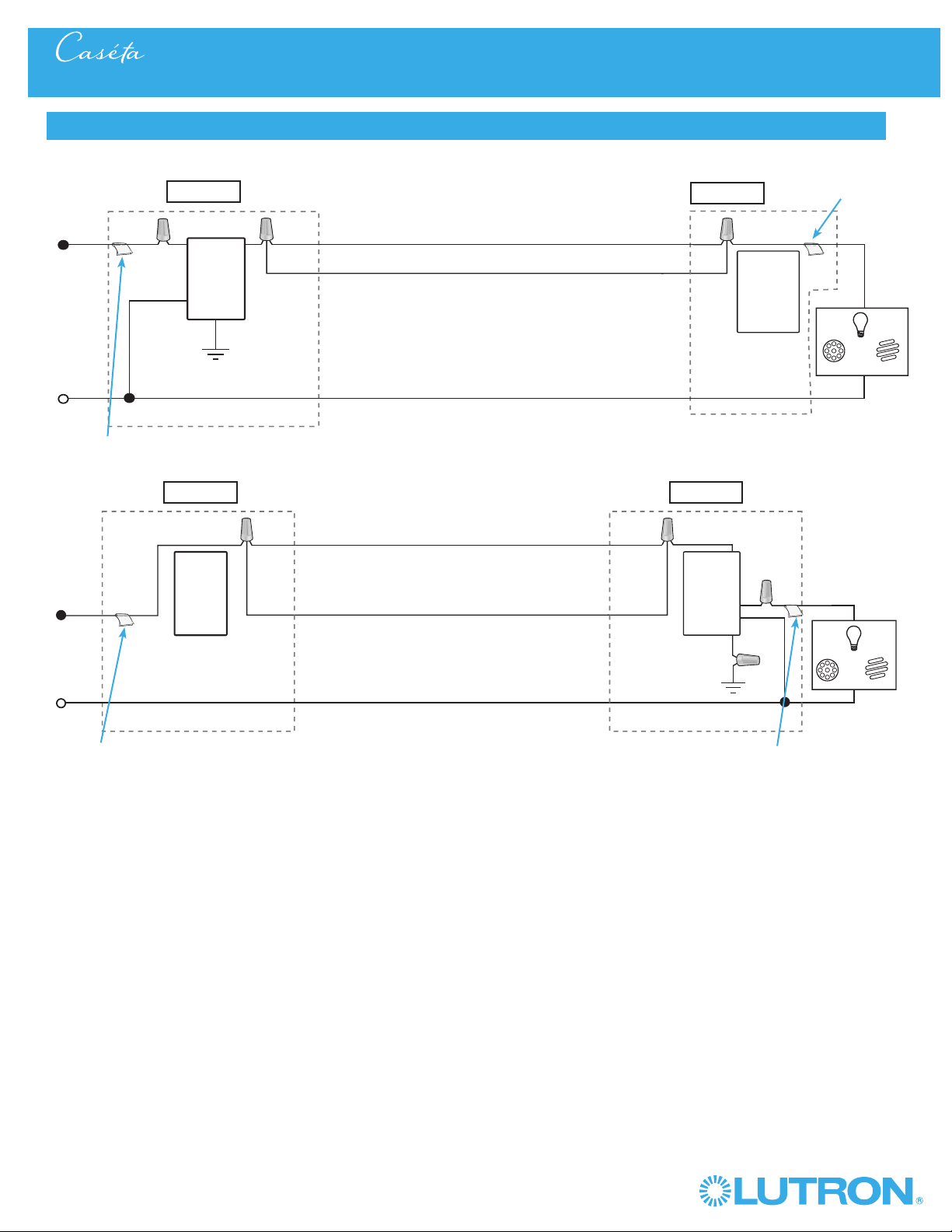
3-Way Installation - Caséta® Wireless In-Wall ELV+ Dimmer with Pico® Remote Control
Schematic Diagram
Black
White
Pico
®
Remote
Control
Caséta
®
Wireless
Dimmer
LFC
A
CFL
AFC
INC /
HAL
LED
DEL
Line / Hot
Neutral
Traveler
Traveler
Ground
Tagged Wire
Tagged Wire
Location 1
Location 2
Neutral
Pico®
Remote
Control
Line / Hot
Traveler
Caséta®
Wireless
Dimmer
Ground
Load
LED
DEL
INC /
HAL
Traveler
Tagged Wire
Tagged Wire
Black
Red
White
Location 1 Location 2
LFC
A
CFL
AFC
22
Wireless
®
1
Identify existing wiring
Two switches control the lights (3-way installation)
2
What you need for a 3-way installation
WARNING! Shock Hazard. May result in serious
injury or death. Turn off power at circuit breaker
before installing the unit.
4
Turn power off at circuit breaker
5
Remove existing switch from wall
6
Tag and disconnect wires from the existing switch
Place tag - to identify wire on
different color screw
Different
Color
Screw
Ground
(Green /
Bare Copper)
3-Way Installation - Caséta® Wireless In-Wall Switch with Mechanical Toggle Switch
Location 1 Location 2
- If one switch controls the lights (single-pole installation)
See quick-start guide that came with your switch
- If three or more switches control the lights
(multi-location installation) See page 41 for details
Important note:
3
Choose a location for your Caséta® Wireless switch
Choose which location you want the Caséta® Wireless switch installed in.
This will be Location 1.
Location 1
Location 1
+
In-wall switch
PD-5WS-DV
Existing mechanical
toggle switch
+
Claro® Wallplate
CW-1
23
Wireless
®
7
Remove side sections (if necessary)
Do not remove outside side sections
on switches at the end of gang.
Each switch has inside
side sections removed.
Switch in the middle has
all side sections removed.
8
Connect the new Caséta® Wireless switch
Tagged Wire
Non-Black
Wire
Ground
(Green Wire)
9
Mount the Caséta® Wireless switch
10
Attach the wallplate
‘snap’
11
Remove existing toggle switch from wall at Location 2
3-Way Installation - Caséta® Wireless In-Wall Switch with Mechanical Toggle Switch
12
Modify wiring for existing toggle switch
Ground (Green / Bare Copper)
Different
Color
Screw
When installing more than one Caséta
® Wireless switch in the same
wallbox, it is necessary to remove inner side sections prior to wiring. See
image and chart below for more information.
Wallplate
Adapter
Wallplate
Location 1
Location 1
Location 2
Add jumper wire as shown
Location 2
Location 1
Important note:
Removing side sections reduces the switch’s maximum wattage
rating. See the chart below for maximum wattage information.
B
B B
C
B
A
PD-5WS-DV (120 V~)
LED 5 A 4 A 3 A
Halogen/incandescent 600 W 450 W 350 W
Electronic Low-Voltage 600 W 450 W 350 W
Magnetic Low-Voltage
1
600 VA / 475 W 450 VA / 350 W 350 VA / 275 W
Fluorescent
2
5 A 4 A 3 A
General Purpose Fan 3 A 3 A 3 A
PD-5WS-DV (277 V~)
LED 5 A 4 A 3 A
Halogen/incandescent 1350 W 1100 W 800 W
Electronic Low-Voltage 1350 W 1100 W 800 W
Magnetic Low-Voltage
1
1350 VA / 1075 W 1100 VA / 875 W 800 VA / 625 W
Fluorescent
2
5 A 4 A 3 A
A
B C
A
B C
1
The maximum lamp wattage is determined by the efficiency of the transformer, with
70% – 85% as typical. For actual transformer efficiency, contact either the fixture or
transformer manufacturer. The total VA rating of the transformer(s) shall not exceed the VA
rating of the in-wall switch.
2
The in-wall switch is ULR Listed for use with all magnetic and electronic fluorescent ballasts.
Black
Blue
Black
Different
Color
Screw
Non-Black
Wire
24
Wireless
®
13
Remount existing switch
14
Turn power on at circuit breaker
3-Way Installation - Caséta® Wireless In-Wall Switch with Mechanical Toggle Switch
Location 2
Neutral
Toggle
Switch
Line / Hot
Traveler
Caséta®
Wireless
Switch*
Load
LED
DEL
LFC
A
CFL
AFC
INC /
HAL
Schematic Diagram
Traveler
* Switch may be installed in either location.
Tagged Wire
Ground
(Green)
Black
Blue
Black
Important note: Pico® remote control
(optional)
If you would like to pair a Pico® remote control to the Caséta® Wireless
in-wall switch, please follow the procedure described in the quick-start
guide that came with your switch.
25
Wireless
®
1
Identify existing wiring
Two switches control the lights (3-way installation)
2
What you need for a 3-way installation
WARNING! Shock Hazard. May result in serious
injury or death. Turn off power at circuit breaker
before installing the unit.
4
Turn power off at circuit breaker
5
Remove existing switch from wall
6
Tag and disconnect wires from the existing switch
Place tag - to identify wire on
different color screw
Different
Color
Screw
Ground
(Green /
Bare Copper)
3-Way Installation - Caséta® Wireless In-Wall PRO Dimmer with Mechanical Toggle Switch
Location 1 Location 2
- If one switch controls the lights (single-pole installation)
See quick-start guide that came with your switch
- If three or more switches control the lights
(multi-location installation) See page 36 for details
Important note:
3
Choose a location for your Caséta® Wireless dimmer
Choose which location you want the Caséta® Wireless dimmer installed in.
This will be Location 1.
Location 1
Location 1
+
In-wall PRO dimmer
PD-10NXD
Existing mechanical
toggle switch
+
Claro® Wallplate
CW-1
26
Wireless
®
7
Remove side sections (if necessary)
Do not remove outside side sections
on switches at the end of gang.
Each dimmer has inside
side sections removed.
Dimmer in the middle has
all side sections removed.
8
Connect the new Caséta® Wireless dimmer
Tagged Wire
Note wire color
tied to blue wire
Ground
(Green Wire)
White *
9
Mount the Caséta® Wireless dimmer
10
Attach the wallplate
11
Remove existing toggle switch from wall at Location 2
3-Way Installation - Caséta® Wireless In-Wall PRO Dimmer with Mechanical Toggle Switch
12a
Modify wiring for existing toggle switch
When installing more than one Caséta® Wireless dimmer in the same
wallbox, it is necessary to remove inner side sections prior to wiring. See
image and chart below for more information.
Location 1
Location 2
Location 1
Red
Blue
Black
‘snap’
Wallplate
Adapter
Wallplate
Location 1
* If available,
connect the
neutral wire from
the wallbox to the
white wire on the
dimmer. If neutral
is not available,
cap the white
wire with a wire
connector.
Neutral required
for: MLV loads,
LED drivers,
PHPM-PA,
PHPM-3F,
GRX-TVI.
Total Dimmable LED Wattage Incandescent/Halogen Total Wattage
0 W + 1000 W 800 W 600 W
1 W – 25 W + 900 W 750 W 550 W
26 W – 50 W + 800 W 700 W 500 W
51 W – 75 W + 700 W 600 W 450 W
76 W – 100 W + 600 W 500 W 400 W
101 W – 125 W + 500 W 400 W 300 W
126 W – 150 W + 400 W 300 W 200 W
151 W – 175 W + 300 W 200 W 100 W
176 W – 200 W + 200 W 100 W 50 W
201 W – 225 W + 100 W 50 W 0 W
226 W – 250 W + 0 W 0 W 0 W
A
B
C
B
B B
C
B
A
Important note:
Removing side sections reduces the dimmer’s maximum wattage
rating. See the chart below for maximum wattage information.
Ground - Green / Bare Copper
(keep connected to switch)
Different Color
Screw / Tagged Wire
(disconnect from switch)
Noted wire color
from Step 8
(keep connected to switch)
Location 2
Remaining Wire
(disconnect from switch)
27
Wireless
®
13
Remount existing switch
14
Turn power on at circuit breaker
3-Way Installation - Caséta® Wireless In-Wall PRO Dimmer with Mechanical Toggle Switch
Location 2
Neutral
Toggle
Switch
Line / Hot
Traveler
Caséta®
Wireless
Dimmer*
Load
LED
DEL
LFC
A
CFL
AFC
INC /
HAL
Schematic Diagram
Traveler
* Dimmer may be installed in either location.
Tagged Wire
Ground
(Green)
Red
White
Blue
Black
Important note: Pico® remote control
(optional)
If you would like to pair a Pico® remote control to the Caséta® Wireless
in-wall dimmer, please follow the procedure described in the quick-start
guide that came with your dimmer.
If available, connect the neutral wire
from the wallbox to the white wire on the
dimmer. If neutral is not available, cap the
white wire with a wire connector.
Neutral required for: MLV loads, LED
drivers, PHPM-PA, PHPM-3F, GRX-TVI.
12b
Modify wiring for existing toggle switch
Location 2
Different Color Screw /
Tagged Wire
Jumper wire
(included in box)
Noted wire color
from Step 8
Remaining wire
Ground
(Green / Bare
Copper)

28
Wireless
®
1
Identify existing wiring
Two switches control the lights (3-way installation)
2
What you need for a 3-way installation
WARNING! Shock Hazard. May result in serious
injury or death. Turn off power at circuit breaker
before installing the unit.
4
Turn power off at circuit breaker
5
Remove existing switch from wall
6
Tag and disconnect wires from the existing switch
Place tag - to identify wire on
different color screw
Different
Color
Screw
Ground
(Green /
Bare Copper)
3-Way Installation - Caséta® Wireless In-Wall Neutral Switch with Mechanical Toggle Switch
Location 1 Location 2
- If one switch controls the lights (single-pole installation)
See quick-start guide that came with your switch
- If three or more switches control the lights
(multi-location installation) See page 46 for details
Important note:
3
Choose a location for your Caséta® Wireless switch
Choose which location you want the Caséta® Wireless dimmer installed in.
This will be Location 1.
Location 1
Location 1
+
Existing mechanical
toggle switch
+
Claro® Wallplate
CW-1
In-wall switch
PD-6ANS
Neutral
connection
required
29
Wireless
®
7
Remove side sections (if necessary)
8
Connect the new Caséta® Wireless neutral switch
Tagged Wire
Note wire color
tied to blue wire
Ground
(Green Wire)
White
9
Mount the Caséta® Wireless switch
10
Attach the wallplate
11
Remove existing toggle switch from wall at Location 2
3-Way Installation - Caséta® Wireless In-Wall Neutral Switch with Mechanical Toggle Switch
12a
Modify wiring for existing toggle switch
Ground - Green / Bare Copper
(keep connected to switch)
Different Color
Screw / Tagged Wire
(disconnect from switch)
Noted wire color
from Step 8
(keep connected to switch)
When installing more than one Caséta
® Wireless switch in the same
wallbox, it is necessary to remove inner side sections prior to wiring. See
image and chart below for more information.
Location 2
Location 2
Location 1
Red
Blue
Black
Important note:
Removing side sections reduces the switch’s maximum wattage
rating. See the chart below for maximum wattage information.
Neutral
connection
required
1
Neutral required.
2
The maximum lamp wattage is determined by the efficiency of the transformer, with
70% – 85% as typical. For actual transformer efficiency, contact either the fixture or
transformer manufacturer. The total VA rating of the transformer(s) shall not exceed the VA
rating of the in-wall switch.
3
The in-wall switch is ULR Listed for use with all magnetic and electronic fluorescent ballasts.
B
B B
C
B
A
PD-6ANS (120 V~)
1
LED 6 A 6 A 5 A
Halogen / incandescent 720 W 720 W 600 W
Electronic Low-Voltage 720 VA 720 VA 600 VA
Magnetic Low-Voltage
2
720 VA 720 VA 600 VA
Fluorescent
3
6 A 6 A 5 A
General Purpose Fan 3.6 A 3.6 A 3.6 A
A
B C
Do not remove outside side sections
on switches at the end of gang.
Each switch has inside
side sections removed.
Switch in the middle has
all side sections removed.
‘snap’
Wallplate
Adapter
Wallplate
Location 1
Location 1
Remaining Wire
(disconnect from switch)
30
Wireless
®
13
Remount existing switch
14
Turn power on at circuit breaker
3-Way Installation - Caséta® Wireless In-Wall Neutral Switch with Mechanical Toggle Switch
Location 2
Location 2
Neutral
Toggle
Switch
Line / Hot
Traveler
Caséta®
Wireless
Switch*
Load
LED
DEL
INC /
HAL
Schematic Diagram
Traveler
Tagged Wire
Ground
(Green)
Red
White
Blue
Black
Important note: Pico® remote control
(optional)
If you would like to pair a Pico® remote control to the Caséta® Wireless
in-wall switch, please follow the procedure described in the quick-start
guide that came with your switch.
12b
Modify wiring for existing toggle switch
Different Color Screw /
Tagged Wire
Jumper wire
(included in box)
Noted wire color
from Step 8
Remaining wire
Ground
(Green / Bare
Copper)
* Switch may be installed in either location.
Note: The red wire must be connected to the load and the black wire must be connected to Line/Hot. The product will not work if the wires
are reversed.
31
Wireless
®
Multi-Location Installation - Caséta® Wireless In-Wall Dimmer with Pico® Remote Controls
1
Identify existing wiring
2
What you need for a multi-location installation
WARNING! Shock Hazard. May result in serious
injury or death. Turn off power at circuit breaker
before installing the unit.
4
Turn power off at circuit breaker
5
Remove existing switch from wall at Location 1
+
- If one switch controls the lights (single-pole installation)
See quick-start guide that came with your dimmer
- If two switches control the lights (3-way installation)
See page 2 for details
Important note:
In-wall dimmer
PD-6WCL or P-PKG1W
Two Pico® remote controls with wall-mounting kits
PJ2-WALL
3
Choose a location for your Caséta® Wireless dimmer
NOTE: There will be two different types of existing switches in this
application. Locations 1 and 3 will use 3-way switches (three screws
which control the lights, plus one ground screw) and Location 2 will use
a 4-way switch (four screws which control the lights, plus one ground
screw). For easiest installation, we recommend replacing one of the 3-way
switches with your dimmer (Locations 1 or 3). In this example, we will use
Location 1.
Location 1
3-Way Switch
Locations 1 and 3
4-Way Switch
Location 2
+
Claro® Wallplate
CW-1
Three or more switches control the lights
(multi-location installation)
Location 1 Location 2 Location 3
32
Wireless
®
Multi-Location Installation - Caséta® Wireless In-Wall Dimmer with Pico® Remote Controls
8
Connect the new Caséta® Wireless dimmer
9
Mount the Caséta® Wireless dimmer
10
Attach the wallplate
‘snap’
Ground
(Green / Bare Copper)
Wallplate
Adapter
Wallplate
Tagged wire
Location 1
Location 1
Location 1
6
Tag and disconnect wires from the existing switch
7
Remove side sections (if necessary)
Do not remove outside side sections
on dimmers at the end of gang.
Each dimmer has inside
side sections removed.
Dimmer in the middle has
all side sections removed.
Total Dimmable LED Wattage
Incandescent/Halogen Total Wattage
0 W + 600 W 500 W 400 W
1 W – 25 W + 500 W 400 W 300 W
26 W – 50 W + 400 W 300 W 200 W
51 W – 75 W + 300 W 200 W 100 W
76 W – 100 W + 200 W 100 W 50 W
101 W – 125 W + 100 W 50 W 0 W
126 W – 150 W + 0 W 0 W 0 W
A
B
C
B
B B
C
B
A
When installing more than one Caséta® Wireless dimmer in the same
wallbox, it is necessary to remove inner side sections prior to wiring. See
image and chart below for more information.
Important note:
Removing side sections reduces the dimmer’s maximum wattage
rating. See the chart below for maximum wattage information.
Different
Color Screw
Ground
(Green / Bare Copper)
Place tag - to identify wire on
different color screw
Location 1
33
Wireless
®
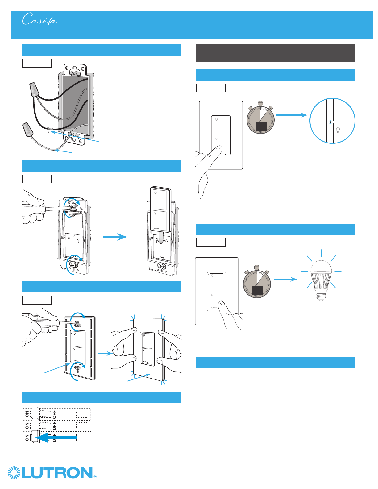
14
Attach the wallplate bracket and Pico® remote control
15
Attach the wallplate
‘snap’
Multi-Location Installation - Caséta® Wireless In-Wall Dimmer with Pico® Remote Controls
16
Remove existing switch from wall at Location 3
Wallplate
Adapter
Wallplate
Location 2
Location 2
13
Connect the wires
Ground
(Green / Bare Copper)
Tagged Wires
Location 2
11
Remove existing switch from wall at Location 2
12
Tag and disconnect wires from the existing switch
Ground (Green / Bare Copper)
Location 2
Location 2
Place tags - to identify wires
on different color screws
Different Color Screws
Location 3

34
Wireless
®
Multi-Location Installation - Caséta® Wireless In-Wall Dimmer with Pico® Remote Controls
21
Turn power on at circuit breaker
Pairing the dimmer and PicoR remote controls
22
Press and hold "Off" button on dimmer
0
5
10
15
6
sec.
UNTIL
HOLD
Status LEDs flash
23
Press and hold "Off" button on remote control
0
5
10
15
6
sec.
UNTIL
Location 2
Location 1
Repeat steps 22 and 23 to pair remote control
at Location 3.
24
Repeat for remote control at Location 3
17
Tag and disconnect wires from the existing switch
Different Color Screw
Ground (Green / Bare Copper)
18
Connect the wires
19
Attach the wallplate bracket and Pico® remote control
Ground (Green / Bare Copper)
Place tag - to
identify wire on
different color screw
Location 3
Tagged Wire
Location 3
Location 3
20
Attach the wallplate
‘snap’
Wallplate
Adapter
Wallplate
Location 3
HOLD
Lights flash
three times
3x

35
Wireless
®
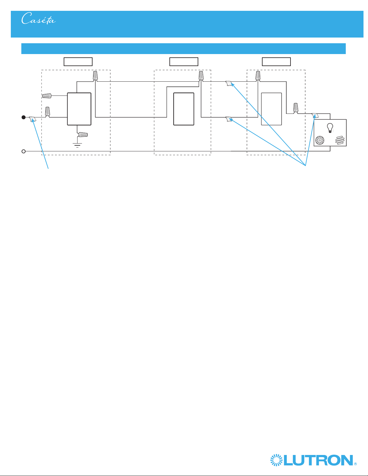
Multi-Location Installation - Caséta® Wireless In-Wall Dimmer with Pico® Remote Controls
Neutral
Pico®
Remote
Control
Line / Hot
Traveler Traveler
Traveler
Traveler
Caséta®
Wireless
Dimmer *
Ground
Load
LED
DEL
LFC
A
CFL
AFC
INC /
HAL
Schematic Diagram
Pico®
Remote
Control
* It is recommended to install dimmer in either Location 1 or 3.
Location 1 Location 2 Location 3
Tagged Wire Tagged Wires
36
Wireless
®
Multi-Location Installation - Caséta® Wireless In-Wall PRO Dimmer with Pico® Remote Controls
1
Identify existing wiring
2
What you need for a multi-location installation
WARNING! Shock Hazard. May result in serious
injury or death. Turn off power at circuit breaker
before installing the unit.
4
Turn power off at circuit breaker
5
Remove existing switch from wall at Location 1
+
- If one switch controls the lights (single-pole installation)
See quick-start guide that came with your dimmer
- If two switches control the lights (3-way installation)
See page 10 or page 25 for details
Important note:
In-wall PRO dimmer
PD-10NXD
Two Pico® remote controls with wall-mounting kits
PJ2-WALL
3
Choose a location for your Caséta® Wireless dimmer
NOTE: There will be two different types of existing switches in this
application. Locations 1 and 3 will use 3-way switches (three screws
which control the lights, plus one ground screw) and Location 2 will use
a 4-way switch (four screws which control the lights, plus one ground
screw). For easiest installation, we recommend replacing one of the 3-way
switches with your dimmer (Locations 1 or 3). In this example, we will use
Location 1.
Location 1
3-Way Switch
Locations 1 and 3
4-Way Switch
Location 2
+
Claro® Wallplate
CW-1
Three or more switches control the lights
(multi-location installation)
Location 1 Location 2 Location 3
37
Wireless
®
Multi-Location Installation - Caséta® Wireless In-Wall PRO Dimmer with Pico® Remote Controls
8
Connect the new Caséta® Wireless dimmer
9
Mount the Caséta® Wireless dimmer
10
Attach the wallplate
‘snap’
Wallplate
Adapter
Wallplate
Location 1
Location 1
Location 1
6
Tag and disconnect wires from the existing switch
7
Remove side sections (if necessary)
Do not remove outside side sections
on dimmers at the end of gang.
Each dimmer has inside
side sections removed.
Dimmer in the middle has
all side sections removed.
When installing more than one Caséta® Wireless dimmer in the same
wallbox, it is necessary to remove inner side sections prior to wiring. See
image and chart below for more information.
Different
Color Screw
Ground
(Green / Bare Copper)
Place tag - to identify wire on
different color screw
Location 1
Tagged Wire
Ground
(Green Wire)
Red
White *
*
If available,
connect the
neutral wire from
the wallbox to the
white wire on the
dimmer. If neutral
is not available,
cap the white
wire with a wire
connector.
Neutral required
for: MLV loads,
LED drivers,
PHPM-PA,
PHPM-3F,
GRX-TVI.
Black
Blue
Total Dimmable LED Wattage Incandescent/Halogen Total Wattage
0 W + 1000 W 800 W 600 W
1 W – 25 W + 900 W 750 W 550 W
26 W – 50 W + 800 W 700 W 500 W
51 W – 75 W + 700 W 600 W 450 W
76 W – 100 W + 600 W 500 W 400 W
101 W – 125 W + 500 W 400 W 300 W
126 W – 150 W + 400 W 300 W 200 W
151 W – 175 W + 300 W 200 W 100 W
176 W – 200 W + 200 W 100 W 50 W
201 W – 225 W + 100 W 50 W 0 W
226 W – 250 W + 0 W 0 W 0 W
A
B
C
B
B B
C
B
A
Important note:
Removing side sections reduces the dimmer’s maximum wattage
rating. See the chart below for maximum wattage information.
Multi-Location Installation - Caséta® Wireless In-Wall PRO Dimmer with Pico® Remote Controls
38
Wireless
®
14
Attach the wallplate bracket and Pico® remote control
15
Attach the wallplate
‘snap’
Multi-Location Installation - Caséta® Wireless In-Wall PRO Dimmer with Pico® Remote Controls
16
Remove existing switch from wall at Location 3
Wallplate
Adapter
Wallplate
Location 2
Location 2
13
Connect the wires
Ground
(Green / Bare Copper)
Tagged Wires
Location 2
11
Remove existing switch from wall at Location 2
12
Tag and disconnect wires from the existing switch
Ground (Green / Bare Copper)
Location 2
Location 2
Place tags - to identify wires
on different color screws
Different Color Screws
Location 3
39
Wireless
®
Multi-Location Installation - Caséta® Wireless In-Wall PRO Dimmer with Pico® Remote Controls
21
Turn power on at circuit breaker
Pairing the dimmer and PicoR remote controls
22
Press and hold "Off" button on dimmer
0
5
10
15
6
sec.
UNTIL
HOLD
Status LEDs flash
23
Press and hold "Off" button on remote control
0
5
10
15
6
sec.
UNTIL
Location 2
Location 1
Repeat steps 22 and 23 to pair remote control
at Location 3.
24
Repeat for remote control at Location 3
17
Tag and disconnect wires from the existing switch
Different Color Screw
Ground (Green / Bare Copper)
18
Connect the wires
19
Attach the wallplate bracket and Pico® remote control
Ground (Green / Bare Copper)
Place tag - to
identify wire on
different color screw
Location 3
Tagged Wire
Location 3
Location 3
20
Attach the wallplate
‘snap’
Wallplate
Adapter
Wallplate
Location 3
HOLD
Lights flash
three times
3x
Multi-Location Installation - Caséta® Wireless In-Wall PRO Dimmer with Pico® Remote Controls
40
Wireless
®
Multi-Location Installation - Caséta® Wireless In-Wall PRO Dimmer with Pico® Remote Controls
Neutral
Pico®
Remote
Control
Line / Hot
Traveler Traveler
Traveler
Traveler
Caséta®
Wireless
Dimmer *
Ground
White
Blue
Load
LED
DEL
LFC
A
CFL
AFC
INC /
HAL
Schematic Diagram
Pico®
Remote
Control
* It is recommended to install
dimmer in either Location 1 or 3.
Location 1 Location 2 Location 3
Tagged Wire Tagged Wires
If available, connect the neutral wire from the
wallbox to the white wire on the dimmer. If neutral
is not available, cap the white wire with a wire
connector.
Neutral required for: MLV loads, LED drivers,
PHPM-PA, PHPM-3F, GRX-TVI.
41
Wireless
®
Multi-Location Installation - Caséta® Wireless In-Wall Switch with Pico® Remote Controls
1
Identify existing wiring
2
What you need for a multi-location installation
WARNING! Shock Hazard. May result in serious
injury or death. Turn off power at circuit breaker
before installing the unit.
4
Turn power off at circuit breaker
5
Remove existing switch from wall at Location 1
- If one switch controls the lights (single-pole installation)
See quick-start guide that came with your switch
- If two switches control the lights (3-way installation)
See page 6 or page 22 for details
Important note:
3
Choose a location for your Caséta® Wireless switch
NOTE: There will be two different types of existing switches in this
application. Locations 1 and 3 will use 3-way switches (three screws
which control the lights, plus one ground screw) and Location 2 will use
a 4-way switch (four screws which control the lights, plus one ground
screw). For easiest installation, we recommend replacing one of the 3-way
switches with your Caséta® Wireless switch (Locations 1 or 3). In this
example, we will use Location 1.
Location 1
3-Way Switch
Locations 1 and 3
4-Way Switch
Location 2
Three or more switches control the lights
(multi-location installation)
Location 1 Location 2 Location 3
+
In-wall switch
PD-5WS-DV
Two Pico®
remote controls
PJ2-2B
Two Wallplate Brackets
PICO-WBX-ADAPT
+
Three Claro® Wallplates
CW-1
+
Multi-Location Installation - Caséta® Wireless In-Wall PRO Dimmer with Pico® Remote Controls

42
Wireless
®
8
Connect the new Caséta® Wireless switch
9
Mount the Caséta® Wireless switch
10
Attach the wallplate
‘snap’
Wallplate
Adapter
Wallplate
Tagged wire
Location 1
Location 1
Location 1
6
Tag and disconnect wires from the existing switch
7
Remove side sections (if necessary)
Different
Color Screw
Ground
(Green / Bare Copper)
Place tag - to identify wire on
different color screw
Location 1
Multi-Location Installation - Caséta® Wireless In-Wall Switch with Pico® Remote Controls
Do not remove outside side sections
on switches at the end of gang.
Each switch has inside
side sections removed.
Switch in the middle has
all side sections removed.
When installing more than one Caséta® Wireless switch in the same
wallbox, it is necessary to remove inner side sections prior to wiring. See
image and chart below for more information.
Important note:
Removing side sections reduces the switch’s maximum wattage
rating. See the chart below for maximum wattage information.
B
B B
C
B
A
PD-5WS-DV (120 V~)
LED 5 A 4 A 3 A
Halogen/incandescent 600 W 450 W 350 W
Electronic Low-Voltage 600 W 450 W 350 W
Magnetic Low-Voltage
1
600 VA / 475 W 450 VA / 350 W 350 VA / 275 W
Fluorescent
2
5 A 4 A 3 A
General Purpose Fan 3 A 3 A 3 A
PD-5WS-DV (277 V~)
LED 5 A 4 A 3 A
Halogen/incandescent 1350 W 1100 W 800 W
Electronic Low-Voltage 1350 W 1100 W 800 W
Magnetic Low-Voltage
1
1350 VA / 1075 W 1100 VA / 875 W 800 VA / 625 W
Fluorescent
2
5 A 4 A 3 A
A
B C
A
B C
1
The maximum lamp wattage is determined by the efficiency of the transformer, with
70% – 85% as typical. For actual transformer efficiency, contact either the fixture or
transformer manufacturer. The total VA rating of the transformer(s) shall not exceed the VA
rating of the in-wall switch.
2
The in-wall switch is ULR Listed for use with all magnetic and electronic fluorescent ballasts.
Black
Blue
Black
Ground
(Green Wire)
43
Wireless
®
14
Attach the wallplate bracket and Pico® remote control
15
Attach the wallplate
‘snap’
Multi-Location Installation - Caséta® Wireless In-Wall Switch with Pico® Remote Controls
16
Remove existing switch from wall at Location 3
Wallplate
Adapter
Wallplate
Location 2
Location 2
13
Connect the wires
Ground
(Green / Bare Copper)
Tagged Wires
Location 2
11
Remove existing switch from wall at Location 2
12
Tag and disconnect wires from the existing switch
Ground (Green / Bare Copper)
Location 2
Location 2
Place tags - to identify wires
on different color screws
Different Color Screws
Location 3
44
Wireless
®
Multi-Location Installation - Caséta® Wireless In-Wall Switch with Pico® Remote Controls
21
Turn power on at circuit breaker
Pairing the switch and PicoR remote controls
22
Press and hold "Off" button on switch
0
5
10
15
6
sec.
UNTIL
HOLD
Status LED flashes
23
Press and hold "Off" button on remote control
0
5
10
15
6
sec.
UNTIL
Location 2
Location 1
Repeat steps 22 and 23 to pair remote control
at Location 3.
24
Repeat for remote control at Location 3
17
Tag and disconnect wires from the existing switch
Different Color Screw
Ground (Green / Bare Copper)
18
Connect the wires
19
Attach the wallplate bracket and Pico® remote control
Ground (Green / Bare Copper)
Place tag - to
identify wire on
different color screw
Location 3
Tagged Wire
Location 3
Location 3
20
Attach the wallplate
‘snap’
Wallplate
Adapter
Wallplate
Location 3
HOLD
Lights flash
three times
3x
45
Wireless
®
Multi-Location Installation - Caséta® Wireless In-Wall Switch with Pico® Remote Controls
Neutral
Pico®
Remote
Control
Line / Hot
Traveler Traveler
Traveler
Traveler
Caséta®
Wireless
Switch *
Ground
(Green)
Load
LED
DEL
LFC
A
CFL
AFC
INC /
HAL
Schematic Diagram
Pico®
Remote
Control
* It is recommended to install switch in either Location 1 or 3.
Location 1 Location 2 Location 3
Tagged Wire Tagged Wires
Blue
Black
Black
46
Wireless
®
Multi-Location Installation - Caséta® Wireless In-Wall Neutral Switch with Pico® Remote Controls
1
Identify existing wiring
2
What you need for a multi-location installation
WARNING! Shock Hazard. May result in serious
injury or death. Turn off power at circuit breaker
before installing the unit.
4
Turn power off at circuit breaker
5
Remove existing switch from wall at Location 1
- If one switch controls the lights (single-pole installation)
See quick-start guide that came with your switch
- If two switches control the lights (3-way installation)
See page 14 or page 28 for details
Important note:
3
Choose a location for your Caséta® Wireless switch
NOTE: There will be two different types of existing switches in this
application. Locations 1 and 3 will use 3-way switches (three screws
which control the lights, plus one ground screw) and Location 2 will use
a 4-way switch (four screws which control the lights, plus one ground
screw). For easiest installation, we recommend replacing one of the 3-way
switches with your Caséta® Wireless switch (Locations 1 or 3). In this
example, we will use Location 1.
Location 1
3-Way Switch
Locations 1 and 3
4-Way Switch
Location 2
Three or more switches control the lights
(multi-location installation)
Location 1 Location 2 Location 3
+
In-wall switch
PD-6ANS
Two Pico®
remote controls
PJ2-2B
Two Wallplate Brackets
PICO-WBX-ADAPT
+
Three Claro® Wallplates
CW-1
+
47
Wireless
®
Multi-Location Installation - Caséta® Wireless In-Wall Neutral Switch with Pico® Remote Controls
8
Connect the new Caséta® Wireless neutral switch
9
Mount the Caséta® Wireless neutral switch
10
Attach the wallplate
‘snap’
Wallplate
Adapter
Wallplate
Tagged wire
Location 1
Location 1
Location 1
6
Tag and disconnect wires from the existing switch
7
Remove side sections (if necessary)
Different
Color Screw
Ground
(Green / Bare Copper)
Place tag - to identify wire on
different color screw
Location 1
Multi-Location Installation - Caséta® Wireless In-Wall Neutral Switch with Pico® Remote Controls
Do not remove outside side sections
on switches at the end of gang.
Each switch has inside
side sections removed.
Switch in the middle has
all side sections removed.
When installing more than one Caséta® Wireless switch in the same
wallbox, it is necessary to remove inner side sections prior to wiring. See
image and chart below for more information.
Important note:
Removing side sections reduces the switch’s maximum wattage
rating. See the chart below for maximum wattage information.
Black
Blue
Red
Ground
(Green Wire)
Neutral
connection
required
1
Neutral required.
2
The maximum lamp wattage is determined by the efficiency of the transformer, with
70% – 85% as typical. For actual transformer efficiency, contact either the fixture or
transformer manufacturer. The total VA rating of the transformer(s) shall not exceed the VA
rating of the in-wall switch.
3
The in-wall switch is ULR Listed for use with all magnetic and electronic fluorescent ballasts.
B
B B
C
B
A
PD-6ANS (120 V~)
1
LED 6 A 6 A 5 A
Halogen / incandescent 720 W 720 W 600 W
Electronic Low-Voltage 720 VA 720 VA 600 VA
Magnetic Low-Voltage
2
720 VA 720 VA 600 VA
Fluorescent
3
6 A 6 A 5 A
General Purpose Fan 3.6 A 3.6 A 3.6 A
A
B C
White
Neutral
connection
required

48
Wireless
®
14
Attach the wallplate bracket and Pico® remote control
15
Attach the wallplate
‘snap’
Multi-Location Installation - Caséta® Wireless In-Wall Neutral Switch with Pico® Remote Controls
16
Remove existing switch from wall at Location 3
Wallplate
Adapter
Wallplate
Location 2
Location 2
13
Connect the wires
Ground
(Green / Bare Copper)
Tagged Wires
Location 2
11
Remove existing switch from wall at Location 2
12
Tag and disconnect wires from the existing switch
Ground (Green / Bare Copper)
Location 2
Location 2
Place tags - to identify wires
on different color screws
Different Color Screws
Location 3
49
Wireless
®
Multi-Location Installation - Caséta® Wireless In-Wall Neutral Switch with Pico® Remote Controls Multi-Location Installation - Caséta® Wireless In-Wall Neutral Switch with Pico® Remote Controls
21
Turn power on at circuit breaker
Pairing the switch and PicoR remote controls
22
Press and hold "Off" button on switch
0
5
10
15
6
sec.
UNTIL
HOLD
Status LED flashes
23
Press and hold "Off" button on remote control
0
5
10
15
6
sec.
UNTIL
Location 2
Location 1
Repeat steps 22 and 23 to pair remote control
at Location 3.
24
Repeat for remote control at Location 3
17
Tag and disconnect wires from the existing switch
Different Color Screw
Ground (Green / Bare Copper)
18
Connect the wires
19
Attach the wallplate bracket and Pico® remote control
Ground (Green / Bare Copper)
Place tag - to
identify wire on
different color screw
Location 3
Tagged Wire
Location 3
Location 3
20
Attach the wallplate
‘snap’
Wallplate
Adapter
Wallplate
Location 3
HOLD
Lights flash
three times
3x
50
Wireless
®
Multi-Location Installation - Caséta® Wireless In-Wall Neutral Switch with Pico® Remote Controls
Neutral
Pico®
Remote
Control
Line / Hot
Traveler Traveler
Traveler
Traveler
Caséta®
Wireless
Switch *
Ground
(Green)
Load
LED
DEL
INC /
HAL
Schematic Diagram
Pico®
Remote
Control
Location 1 Location 2 Location 3
Tagged Wire Tagged Wires
Blue
Black
Red
White
* It is recommended to install switch in either Location 1 or 3.
Note: The red wire must be connected to the load and the black wire must be connected to Line/Hot. The product will not work if the wires
are reversed.
51
Wireless
®
Multi-Location Installation - Caséta® Wireless In-Wall Neutral Switch with Pico® Remote Controls Multi-Location Installation - Caséta® Wireless In-Wall ELV+ Dimmer with Pico® Remote Controls
1
Identify existing wiring
2
What you need for a multi-location installation
WARNING! Shock Hazard. May result in serious
injury or death. Turn off power at circuit breaker
before installing the unit.
4
Turn power off at circuit breaker
5
Remove existing switch from wall at Location 1
+
- If one switch controls the lights (single-pole installation)
See quick-start guide that came with your dimmer
- If two switches control the lights (3-way installation)
See page 18 for details
Important note:
ELV+ dimmer
PD-5NE
Two Pico® remote controls with wall-mounting kits
PJ2-WALL
3
Choose a location for your Caséta® Wireless dimmer
NOTE: There will be two different types of existing switches in this
application. Locations 1 and 3 will use 3-way switches (three screws
which control the lights, plus one ground screw) and Location 2 will use
a 4-way switch (four screws which control the lights, plus one ground
screw). For easiest installation, we recommend replacing one of the 3-way
switches with your dimmer (Locations 1 or 3). In this example, we will use
Location 1.
Location 1
3-Way Switch
Locations 1 and 3
4-Way Switch
Location 2
+
Claro® Wallplate
CW-1
Three or more switches control the lights
(multi-location installation)
Location 1 Location 2 Location 3
52
Wireless
®
Multi-Location Installation - Caséta® Wireless In-Wall ELV+ Dimmer with Pico® Remote Controls
8
Connect the new Caséta® Wireless dimmer
9
Mount the Caséta® Wireless dimmer
10
Attach the wallplate
‘snap’
Ground
(Green / Bare Copper)
Wallplate
Adapter
Wallplate
Tagged wire
Red
Black
White
Neutral Required
Location 1
Location 1
Location 1
6
Tag and disconnect wires from the existing switch
7
Remove side sections (if necessary)
Do not remove outside side sections
on dimmers at the end of gang.
Each dimmer has inside
side sections removed.
Dimmer in the middle has
all side sections removed.
When installing more than one Caséta® Wireless dimmer in the same
wallbox, it is necessary to remove inner side sections prior to wiring. See
image and chart below for more information.
Important note:
Removing side sections reduces the dimmer’s maximum wattage
rating. See the chart below for maximum wattage information.
Different
Color Screw
Neutral
Required
Ground
(Green / Bare Copper)
Place tag - to identify wire on
different color screw
Location 1
PD-5NE (120 V~)
1
Incandescent/Halogen Total Wattage
LED 250 W 250 W 250 W
Halogen / Incandescent 500 W 400 W 300 W
Electronics Low-Voltage 500 W 400 W 300 W
Magnetic Low Voltage 400 VA 400 VA 400 VA
A
B
C
B
B B
C
B
A

53
Wireless
®
14
Attach the wallplate bracket and Pico® remote control
15
Attach the wallplate
‘snap’
Multi-Location Installation - Caséta® Wireless In-Wall ELV+ Dimmer with Pico® Remote Controls
16
Remove existing switch from wall at Location 3
Wallplate
Adapter
Wallplate
Location 2
Location 2
13
Connect the wires
Ground
(Green / Bare Copper)
Tagged Wires
Location 2
11
Remove existing switch from wall at Location 2
12
Tag and disconnect wires from the existing switch
Ground (Green / Bare Copper)
Location 2
Location 2
Place tags - to identify wires
on different color screws
Different Color Screws
Location 3
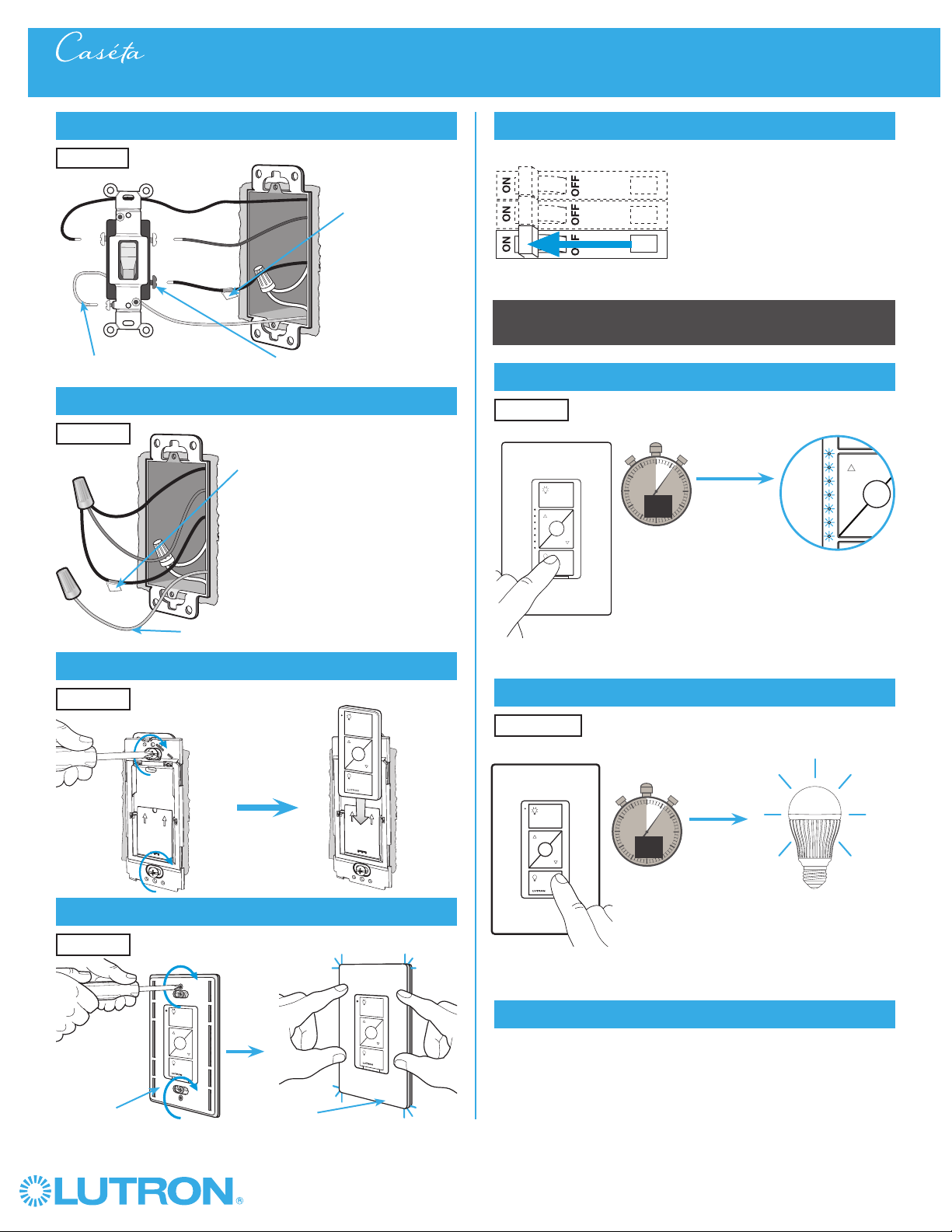
54
Wireless
®
Multi-Location Installation - Caséta® Wireless In-Wall ELV+ Dimmer with Pico® Remote Controls
21
Turn power on at circuit breaker
Pairing the dimmer and PicoR remote controls
22
Press and hold "Off" button on dimmer
0
5
10
15
6
sec.
UNTIL
HOLD
Status LEDs flash
23
Press and hold "Off" button on remote control
0
5
10
15
6
sec.
UNTIL
Location 2
Location 1
Repeat steps 22 and 23 to pair remote control
at Location 3.
24
Repeat for remote control at Location 3
17
Tag and disconnect wires from the existing switch
Different Color Screw
Ground (Green / Bare Copper)
18
Connect the wires
19
Attach the wallplate bracket and Pico® remote control
Ground (Green / Bare Copper)
Place tag - to
identify wire on
different color screw
Location 3
Tagged Wire
Location 3
Location 3
20
Attach the wallplate
‘snap’
Wallplate
Adapter
Wallplate
Location 3
HOLD
Lights flash
three times
3x
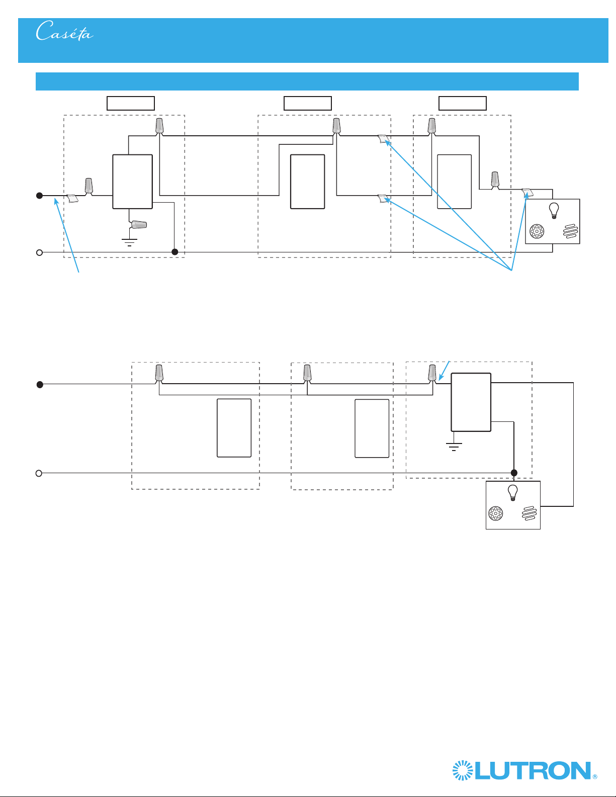
55
Wireless
®
Multi-Location Installation - Caséta® Wireless In-Wall ELV+ Dimmer with Pico® Remote Controls
Neutral
Pico®
Remote
Control
Line / Hot
Traveler Traveler
Traveler
Traveler
Caséta®
Wireless
Dimmer
Ground
Load
LED
DEL
LED
DEL
LFC
A
CFL
AFC
LFC
A
CFL
AFC
INC /
HAL
INC /
HAL
Schematic Diagram
Pico®
Remote
Control
* Neutral Required
Location 1 Location 2 Location 3
Tagged Wire Tagged Wires
Red
Red
Black
Black
Caséta®
Wireless
Dimmer
Traveler Traveler
TravelerTraveler
Line / Hot
Neutral
Ground
White
White
Load
Pico®
Remote
Control
Pico®
Remote
Control
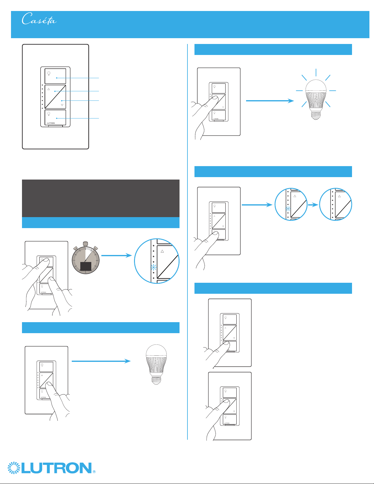
56
Wireless
®
Adjusting Low-End Trim on a Caséta® Wireless In-Wall Dimmer
On
Off
Darker
Brighter
In-wall dimmer
Adjusting Low-End Trim -
To optimize performance of dimmable LED lamps
1
Enter
0
5
10
15
6
sec.
UNTIL
2
Adjust
HOLD
Hold
a.
2
Adjust (continued)
Light stops flickering
and is stable
b.
A status LED starts
flashing
Light stops dimming
or turns off
Status LED stops flashing
4
Verify
a. Tap "Off" one time. Light will
turn off.
b. Tap "Brighter"
one time. Light
will turn on.
c. If light is still off or is flickering,
repeat steps 1-4.
a
.
b.
b.
3
Save
UNTIL
HOLD
UNTIL
TAP
UNTIL
HOLD

57
Wireless
®
Adjusting High-End Trim on a Caséta® Wireless In-Wall Dimmer
Adjusting High-End Trim -
To optimize performance of dimmable LED lamps
1
Enter
0
5
10
15
6
sec.
2
Adjust
Hold
a.
2
Adjust (continued)
Desired light
level is achieved
b.
A status LED starts
flashing
Status LED stops flashing
3
Save
Light is at full
brightness
On
Off
Darker
Brighter
In-wall dimmer
UNTIL
HOLD
UNTIL
HOLD
UNTIL
HOLD
UNTIL
TAP
Adjusting Low-End Trim on a Caséta® Wireless In-Wall Dimmer

58
Wireless
®
Adjusting Low-End Trim on a Caséta® Wireless In-Wall PRO Dimmer
On
Off
Darker
Brighter
In-wall PRO dimmer
Adjusting Low-End Trim -
To optimize performance of dimmable LED lamps
1
Enter
0
5
10
15
6
sec.
UNTIL
2
Adjust
HOLD
Hold
a.
2
Adjust (continued)
Light stops flickering
and is stable
b.
A status LED starts
flashing
Light stops dimming
or turns off
Status LED stops flashing
4
Verify
a. Tap "Off" one time. Light will
turn off.
b. Tap "Brighter"
one time. Light
will turn on.
c. If light is still off or is flickering,
repeat steps 1-4.
a
.
b.
b.
3
Save
UNTIL
HOLD
UNTIL
TAP
UNTIL
HOLD
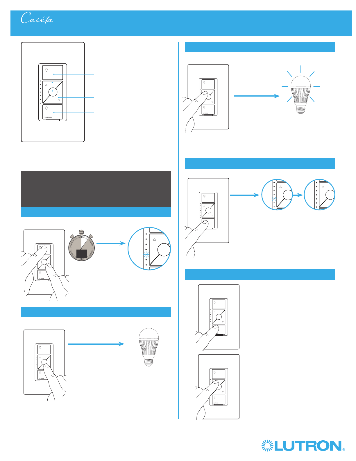
59
Wireless
®
Adjusting Low-End Trim on a Caséta® Wireless In-Wall PRO Dimmer Adjusting Low-End Trim on a Caséta® Wireless In-Wall ELV+ Dimmer
On
Off
Darker
Brighter
In-wall dimmer
Adjusting Low-End Trim -
To optimize performance of dimmable LED lamps
1
Enter
0
5
10
15
6
sec.
UNTIL
2
Adjust
HOLD
(ON AND DARKER)
Hold
a.
2
Adjust (continued)
Light stops flickering
and is stable
b.
A status LED starts
flashing
Light stops dimming
or turns off
Status LED stops flashing
4
Verify
a. Tap "Off" one time. Light will
turn off.
b. Tap "Brighter"
one time. Light
will turn on.
c. If light is still off or is flickering,
repeat steps 1-4.
a
.
b.
b.
3
Save
UNTIL
HOLD
UNTIL
TAP
UNTIL
HOLD
Favorite
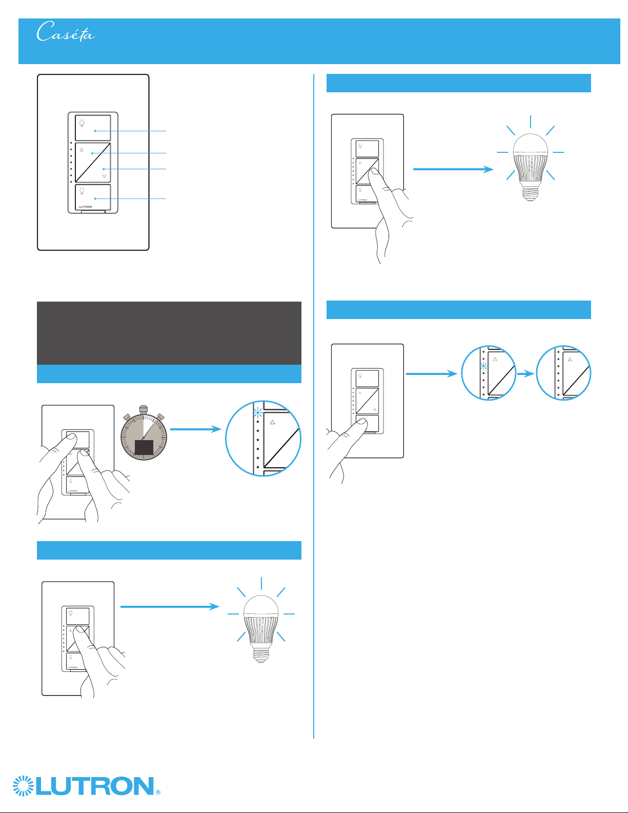
60
Wireless
®
Adjusting High-End Trim on a Caséta® Wireless In-Wall PRO Dimmer
Adjusting High-End Trim -
To optimize performance of dimmable LED lamps
1
Enter
0
5
10
15
6
sec.
2
Adjust
Hold
a.
2
Adjust (continued)
Desired light
level is achieved
b.
A status LED starts
flashing
Status LED stops flashing
3
Save
Light is at full
brightness
On
Off
Darker
Brighter
In-wall PRO dimmer
UNTIL
HOLD
UNTIL
HOLD
UNTIL
HOLD
UNTIL
TAP
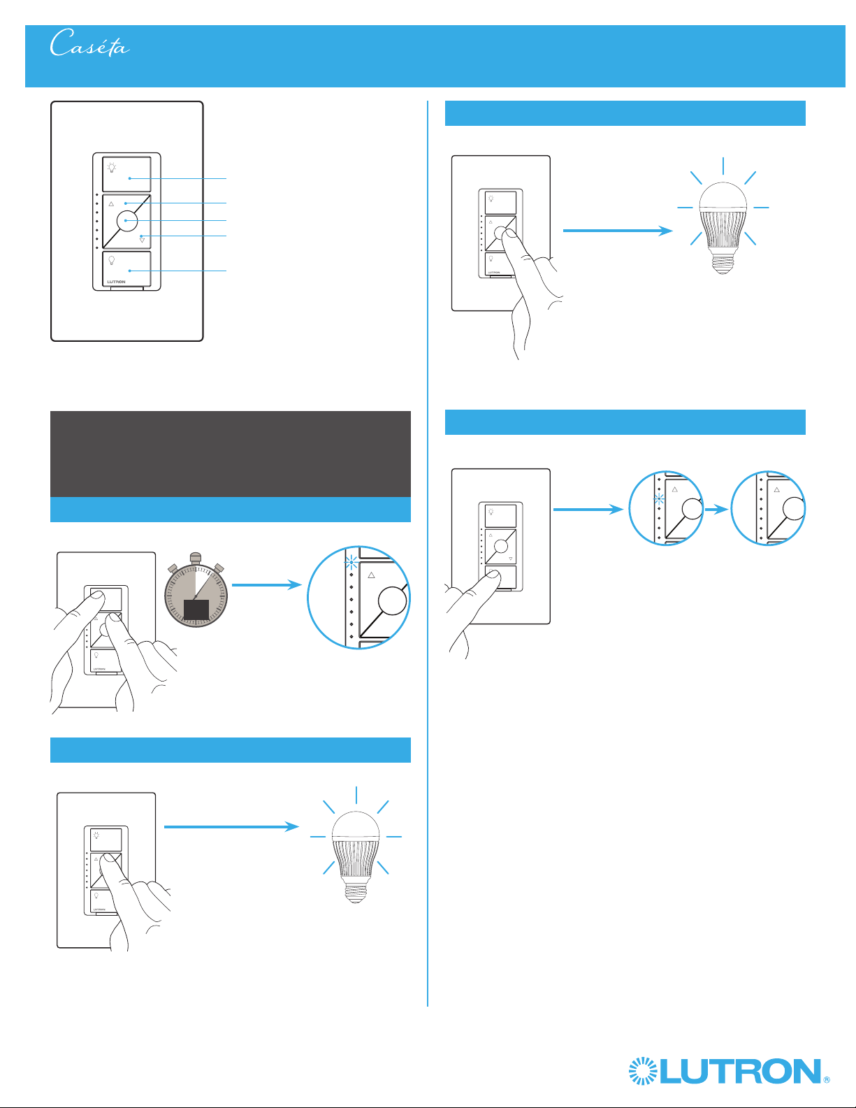
61
Wireless
®
Adjusting High-End Trim on a Caséta® Wireless In-Wall PRO Dimmer Adjusting High-End Trim on a Caséta® Wireless In-Wall ELV+ Dimmer
Adjusting High-End Trim -
To optimize performance of dimmable LED lamps
1
Enter
0
5
10
15
6
sec.
2
Adjust
Hold
a.
2
Adjust (continued)
Desired light
level is achieved
b.
A status LED starts
flashing
Status LED stops flashing
3
Save
Light is at
desired high-end
On
Off
Darker
Brighter
In-wall dimmer
UNTIL
HOLD (ON AND
BRIGHTER)
UNTIL
HOLD
UNTIL
HOLD
UNTIL
TAP
Favorite
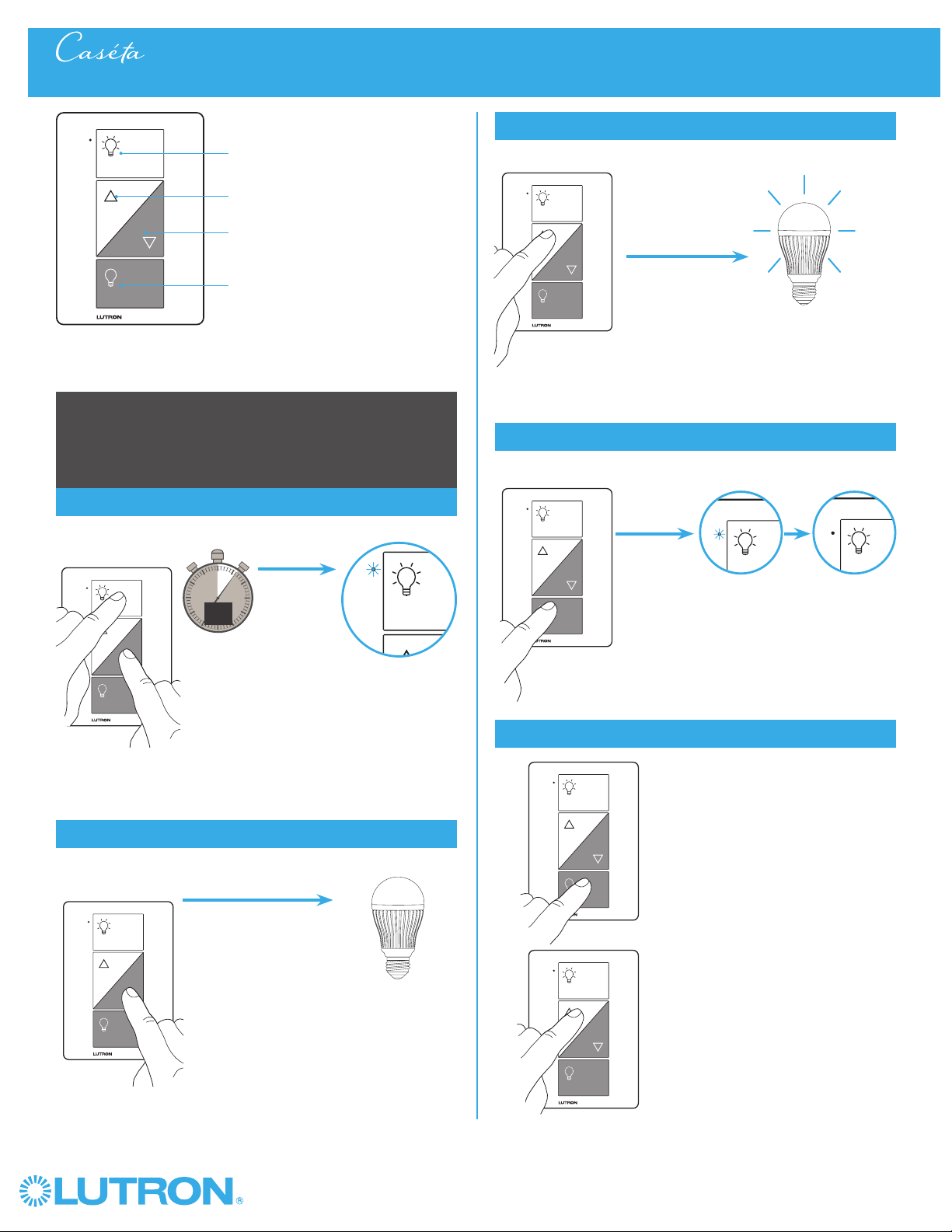
62
Wireless
®
Plug-in lamp dimmer
Adjusting Low-End Trim on a Caséta® Wireless Plug-In Lamp Dimmer
On
Off
Darker
Brighter
Adjusting Low-End Trim -
To optimize performance of dimmable LED lamps
1
Enter
0
5
10
15
6
sec.
2
Adjust
Hold
a.
2
Adjust (continued)
b.
The Status LED
starts flashing
The status LED stops flashing
4
Verify
a.
b.
Light stops dimming
or turns off
Light stops flickering
and is stable
a. Tap "Off" one time. Light will
turn off.
b. Tap "Brighter"
one time. Light
will turn on.
c. If light is still off or is flickering,
repeat steps 1-4.
3
Save
UNTIL
HOLD
UNTIL
HOLD
UNTIL
TAP
UNTIL
HOLD
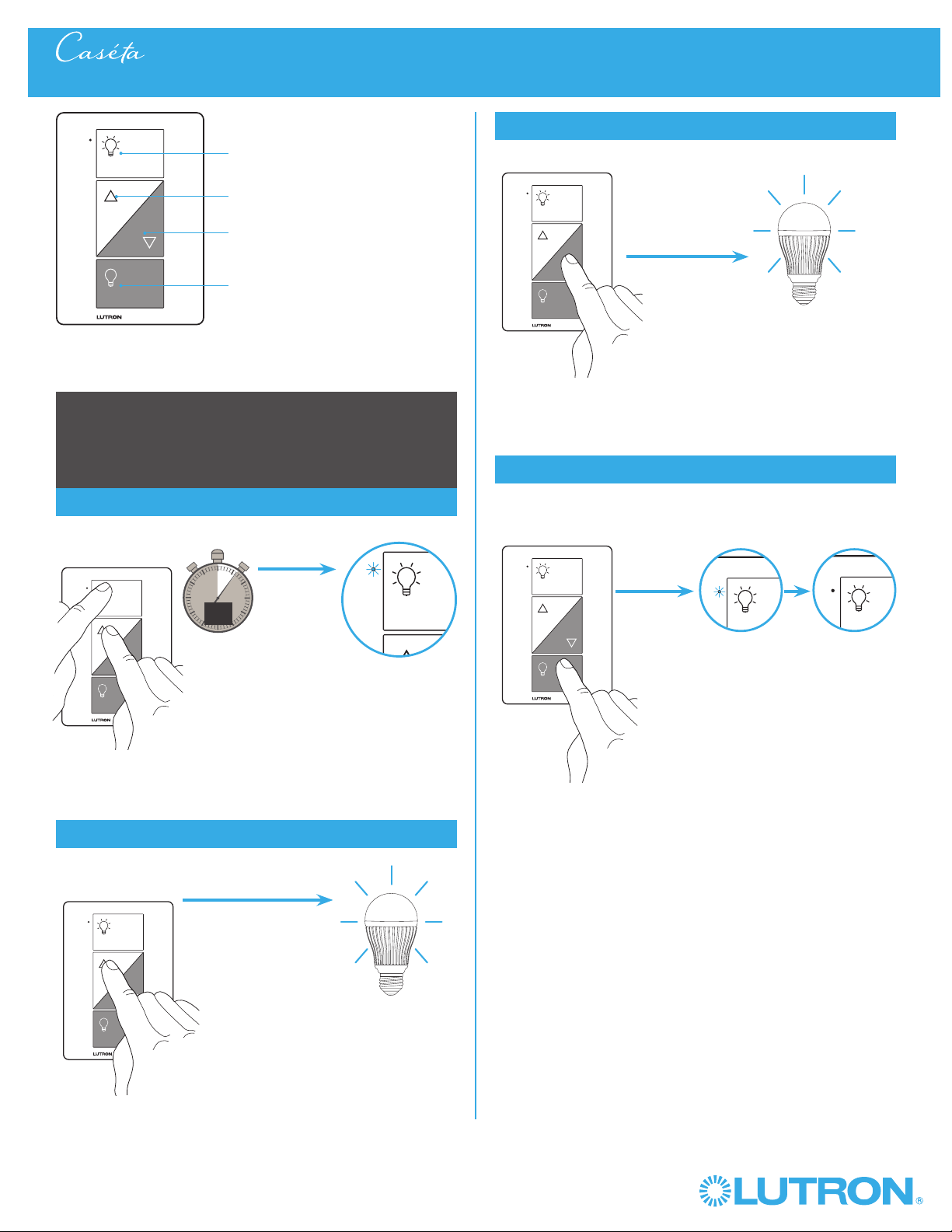
63
Wireless
®
Plug-in lamp dimmer
On
Off
Darker
Brighter
Adjusting High-End Trim -
To optimize performance of dimmable LED lamps
1
Enter
0
5
10
15
6
sec.
2
Adjust
Hold
a.
2
Adjust (continued)
b.
The status LED
starts flashing
Light is at full
brightness
The status LED stops flashing
Desired light
level is achieved
3
Save
Adjusting High-End Trim on a Caséta® Wireless Plug-In Lamp Dimmer
UNTIL
HOLD
UNTIL
HOLD
UNTIL
TAP
UNTIL
HOLD
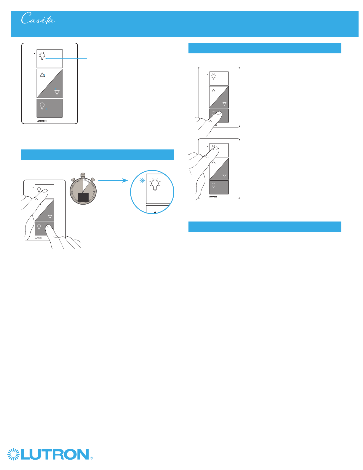
64
Wireless
®
Converting a Caséta® Wireless Plug-In Lamp Dimmer to a Switch to Control Non-Dim Loads
1
Press and Hold "On" and "Off" buttons
0
5
10
15
6
sec.
The indicator light
flashes
2
Verify
a. Tap "Off" one time. Light will
turn off.
b. Tap "On" one time. Light will
turn on.
– The "Brighter" and
"Darker" buttons will be
disabled and do nothing.
NOTE: Only use lighting loads
on your plug-in lamp
dimmer, even when
operating in switch mode.
a.
b.
3
To change back to dimmer mode repeat step 1
Plug-in lamp dimmer
On
Off
Darker
Brighter
UNTIL
HOLD
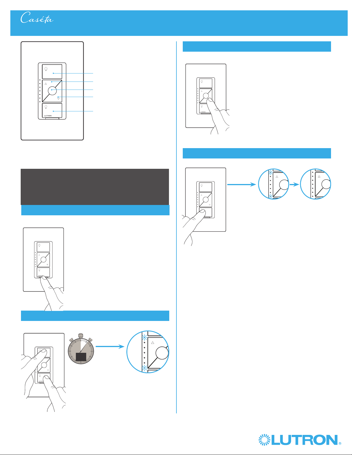
65
Wireless
®
Setting Dimmer Phase on a Caséta® Wireless In-Wall ELV+ Dimmer
On
Off
Darker
Brighter
In-wall ELV+ dimmer
Adjusting for Load Types -
Configurable between ELV and MLV load types
1
Pull out the FASS Switch and then push back in
2
Enter
0
5
10
15
6
sec.
UNTIL
3
Adjust
HOLD
Hold
a.
A status LED starts
flashing
Status LED stops flashing
4
Save
TAP
UNTIL
HOLD
Favorite
NOTE: Top LED Blinking - Forward Phase (MLV)
Bottom LED Blinking - Reverse Phase (ELV)
NOTE: Changes will not be saved if dimmer
times out (no button press for
1 minute) or if power is turned off.
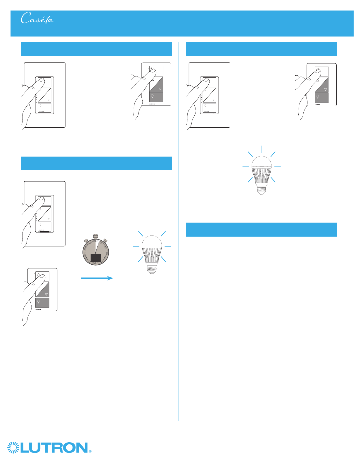
66
Wireless
®
Removing Paired Pico® Remote Controls from a Caséta® Wireless Dimmer
1
Tap the "On" button quickly three times, holding on
the last press
0
5
10
15
3
sec.
2
Continue to hold the "On" button until the light
begins to flash quickly
UNTIL
3
Release the button, then immediately tap the button
three more times
Light will flash slowly
three times, then turn off
4
All paired Pico® remote controls are removed and all
settings are returned to factory default
– After the dimmer resets, the light will turn on to the full on state.
NOTE: This procedure also resets the high-end and low-end trim
settings.
HOLD
HOLD
Light starts
flashing quickly
3x
TAP 3x
TAP 3x
TAP 3x
TAP 3x
OR
OROR
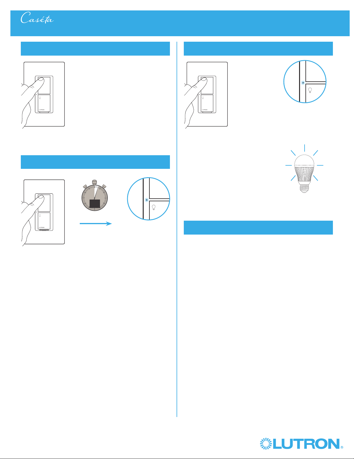
67
Wireless
®
Removing Paired Pico® Remote Controls from a Caséta® Wireless In-Wall Switch
1
Tap the "On" button quickly three times, holding on
the last press
0
5
10
15
3
sec.
2
Continue to hold the "On" button until the Status LED
begins to flash slowly
UNTIL
3
Release the button, then immediately tap the button
three more times
Light will flash slowly
two times
4
All paired Pico® remote controls are removed and all
settings are returned to factory default
– After the switch resets, the light will turn on to the full on state.
2x
Status LED flashes
slowly
HOLD
Status LED flashes
quickly
AND
TAP 3x TAP 3x
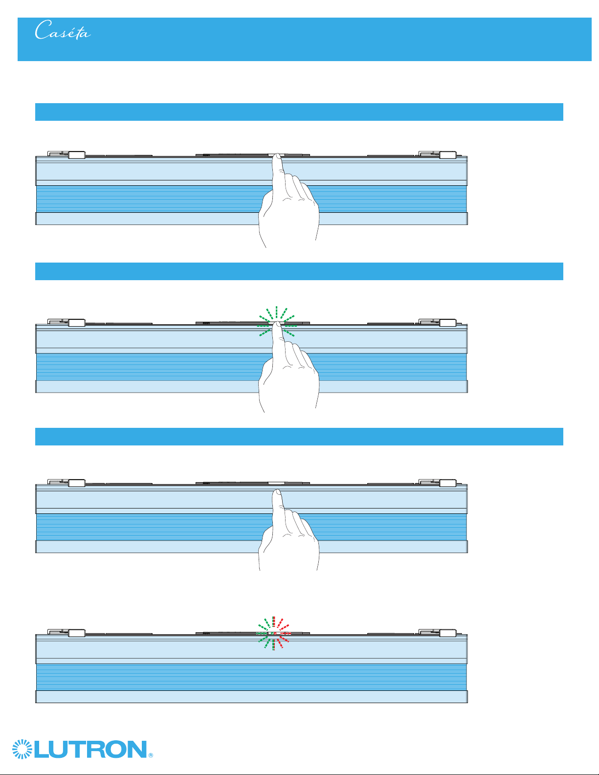
68
Wireless
®
1
Tap the "Shade" button quickly three times, holding on the last press.
3
Release the "Shade" button, then immediately tap the button three more times.
2
Continue to hold the "Shade" button until the button LED flashes green.
HOLD
NOTE: This procedure will remove all paired Pico® remote controls and favorite button programming. Upper and lower limits are retained.
NOTE: The "Shade" button LED will flash GREEN-then-RED three times, signaling the successful completion of the procedure.
3x
Removing Paired Pico® Remote Controls from a Lutron® Honeycomb Shade
TAP 3x
TAP 3x
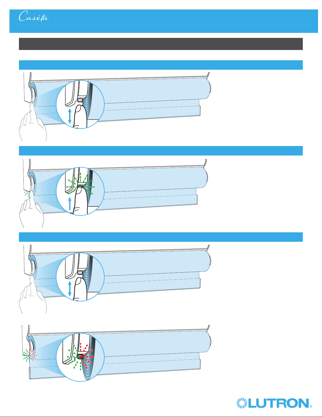
69
Wireless
®
Roller Shades with a Single-Button (Battery-Powered and Plug-In)
Removing Paired Pico® Remote Controls from a Lutron® Roller Shade
1
Tap the "Shade" button quickly three times, holding on the last press.
3
Release the "Shade" button, then immediately tap the button three more times.
2
Continue to hold the "Shade" button until the button LED flashes green.
NOTE: The "Shade" button LED will flash GREEN-then-RED three times, signaling the successful completion of the procedure.
NOTE: This procedure will remove all paired Pico
® remote controls and favorite button programming. Upper and lower limits are retained.
TAP
3x
HOLD
TAP
3x
3x
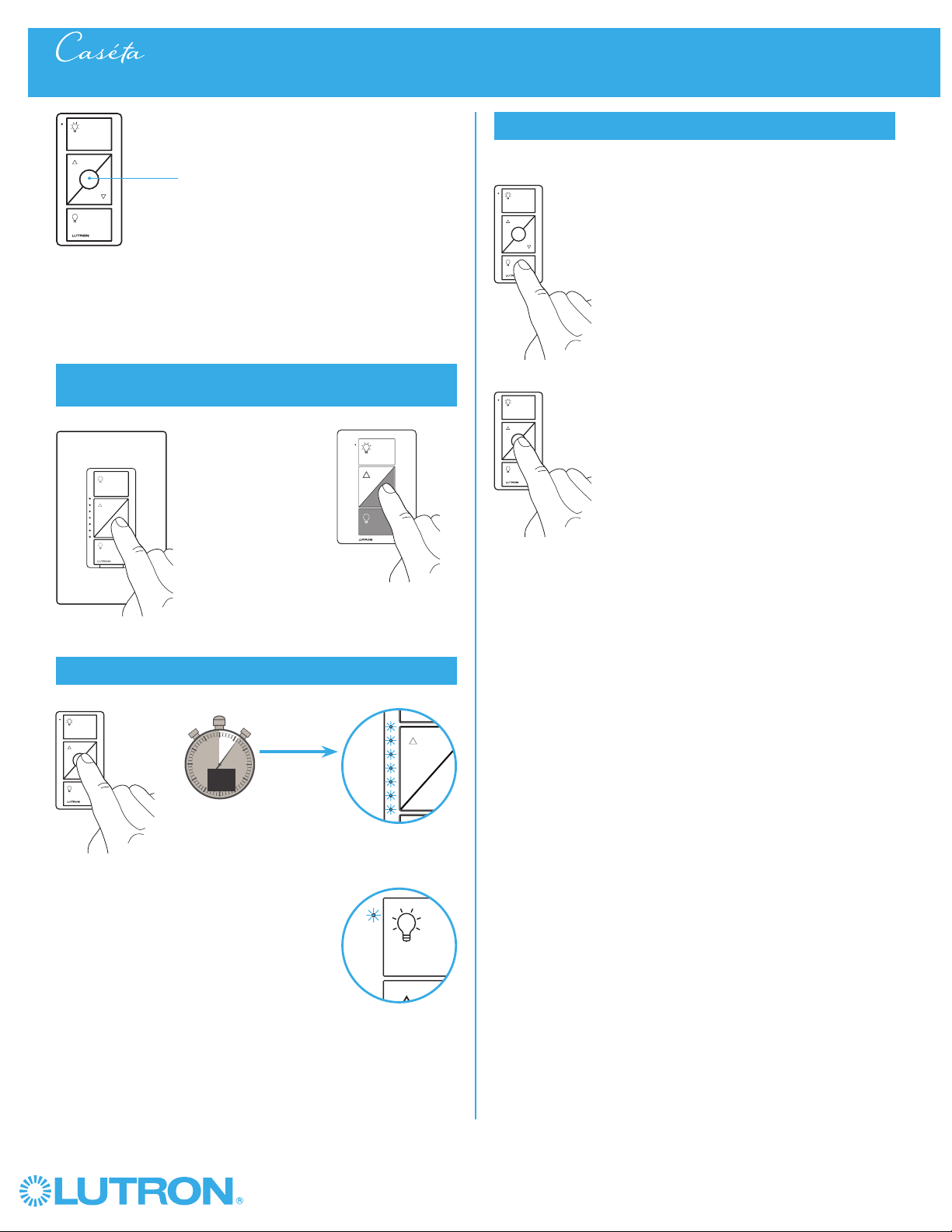
70
Wireless
®
You can use the round “Favorite” button on
a Pico
® remote control to recall a favorite
light level. We’ve set it to 50%, but you can
change it to any level you like.
Favorite
1
Set desired light level on a dimmer that has already
been paired with a remote control
2
Save favorite light level
0
5
10
15
6
sec.
UNTIL
Dimmer LED(s)
flash(es) two times
3
Verify
Changing the Favorite Light Level on a Pico® Remote Control
or
2x
2x
or
a. Tap "Off" button one time
on remote control. Light will
turn off.
b. Tap "Favorite" button one
time on remote control.
Light will turn on to the
newly saved level.
a.
b.
HOLD
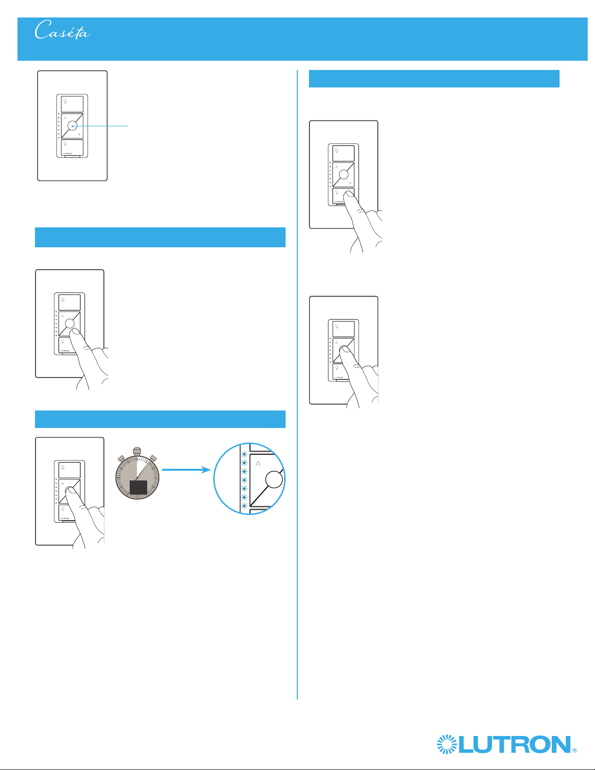
71
Wireless
®
You can use the round “Favorite” button on
the dimmer to recall a favorite light level.
We’ve set it to 50%, but you can change it to
any level you like.
Use the "Brighter" or "Darker" buttons to
adjust lights to your favorite level.
Hold the round "Favorite" button.
1
Set the desired light level on the dimmer
2
Save favorite light level
0
5
10
15
6
sec.
UNTIL
3
Verify
Changing the Favorite Light Level on a Caseta In-wall ELV+ Dimmer
2x
a. Tap "Off" button one time
on dimmer control. Light will
turn off.
b. Tap "Favorite" button one
time on dimmer control.
Light will turn on to the
newly saved level.
a.
b.
Favorite
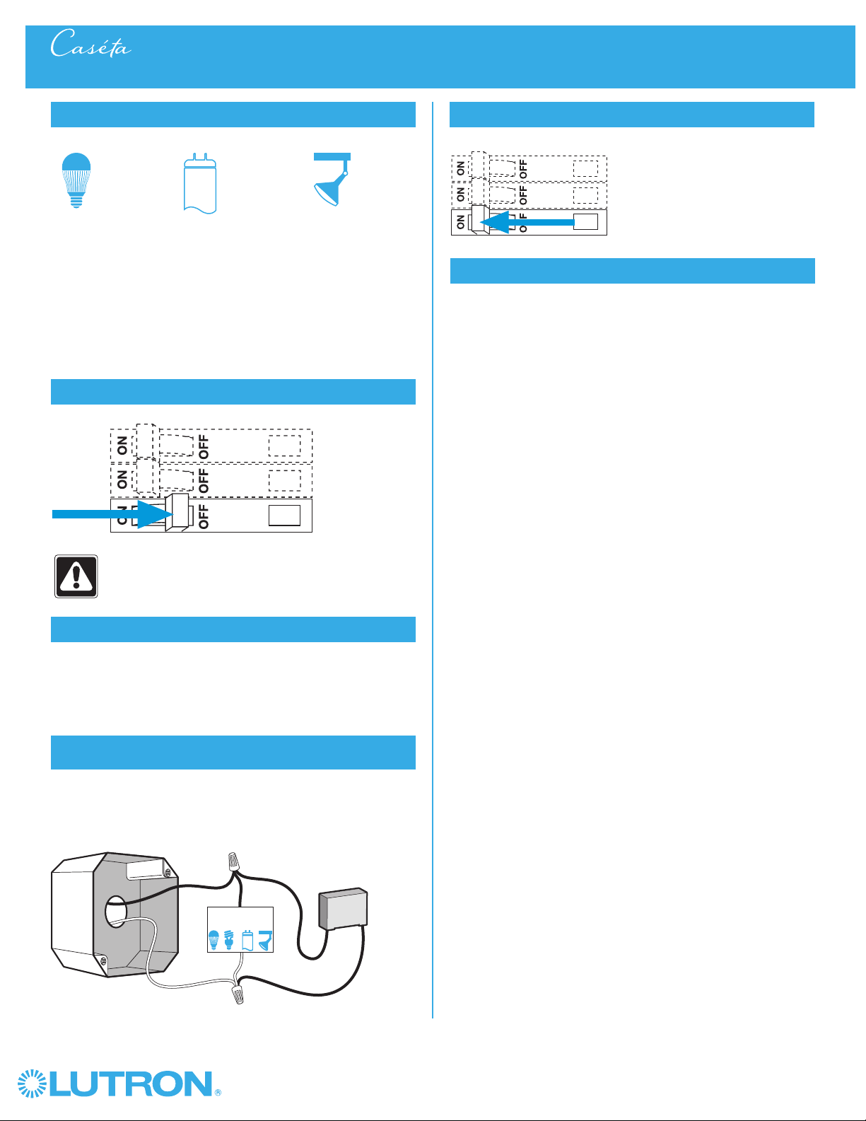
72
Wireless
®
Installing a LUT-MLC Load Adapter with a Caséta® Wireless In-Wall Switch
1
Identify load type
The LUT-MLC load adapter is provided to help ensure proper
operation of the switch with LED, fluorescent, and ELV lighting
loads. When controlling one of these load types, a LUT-MLC
may be required, especially at lower wattages. If the status LED
on the switch is flashing or a solid red color, a LUT-MLC must be
installed. It is recommended to install a LUT-MLC with these load
types regardless of wattage to guarantee best performance.
LED
ELVFluorescent
WARNING! Shock Hazard. May result in serious
injury or death. Turn off power at circuit breaker
before installing the unit.
2
Turn power off at circuit breaker
3
Choose installation location
The LUT-MLC must be connected to the neutral and switched hot
feed to the load. Install the LUT-MLC inside a load fixture or in a
separate junction box within the circuit.
4
Installing the LUT-MLC in a load fixture
or junction box
1. Connect one lead of the LUT-MLC to the neutral (white) wire.
2. Connect the other lead of the LUT-MLC to the switched hot
(black) wire.
1
2
LUT-MLC
Junction Box
Load
5
Turn power on at circuit breaker
6
Verify performance
Verify that the LED on the switch is not flashing or solid red color
and that the load stays off when the switch is turned off. In rare
instances, some loads may still flicker or glow in the off state
with the LUT-MLC installed. If this occurs, a different load may
be required or additional LUT-MLC load adapters may need to
installed.
73
Wireless
®
Lutron Contact Numbers
)Lutron, Lutron, Caséta, Claro and Pico are registered trademarks and FASS is a trademark of Lutron Electronics Co., Inc.
WORLD HEADQUARTERS
USA
Lutron Electronics Co., Inc.
7200 Suter Road
Coopersburg, PA 18036-1299
TEL: +1.610.282.3800
FAX: +1.610.282.1243
Customer Assistance: 1.844.LUTRON1
lutron.com/help
Lutron Electronics Co., Inc.
7200 Suter Road
Coopersburg, PA 18036-1299 U.S.A.
P/N 0301710 Rev. E 08/2016
Troubleshooting
North & South America
Technical Hotlines
USA, Canada, Caribbean:
1.800.523.9466
Mexico:
+1.888.235.2910
Central/South America:
+1.610.282.6701
Symptoms Probable cause and action
Light does not turn on or LEDs on the devices do not
illuminate.
• Light bulb(s) burned out.
• Breaker is OFF or tripped.
• Light not properly installed.
• Wiring error.
In-wall dimmer or switch:
• FASST on the dimmer or switch
is in the off position.
Plug-in lamp dimmer:
• Outlet is switched off.
• Lamp is turned off.
• Lamp is not plugged in.
Light does not respond to PicoR remote control. • The dimmer or switch failed to pair with PicoR remote control.
• The dimmer or switch is already at the light level the PicoR remote
control is sending.
• The PicoR remote control is outside the 30 ft (9 m)
operating range.
• The PicoR remote control battery is low.
• The PicoR remote control battery is installed incorrectly.
• Bulbs turn off while being dimmed.
• Bulbs turn on at high light level but do not turn on at a low
light level.
• Bulbs icker or ash when dimmed to a low light level.
In-wall or plug-in lamp dimmer only:
Verify bulbs are marked dimmable and visit
www.casetawireless.com/lowend for information on adjusting
the dimmer for best bulb performance.
• LED on in-wall switch is ashing or solid red color.
• Light stays on when the in-wall switch is turned off.
In-wall switch only:
Proper bulb operation requires LUT-MLC installation. See Page 59.
Top and middle LEDs are blinking rapidly. Product detected an MLV fault (PRO Dimmer only)
• Connect Neutral to the dimmer (required for MLV load)
Top and second from bottom LEDs are blinking rapidly. No Load (PRO Dimmer only)
• Apply or replace the load
Top three LEDs flashing Over voltage detected, verify unit does not have MLV load and is in
reverse phase
Middle three LEDs flashing Over temperature event, verify unit is not overloaded
Bottom three LEDs flashing Over current detected, verify unit does not have ELV load while in
forward phase
Go to www.casetawireless.com/support for additional troubleshooting suggestions.