User manual Thermostat
SYSTEM INSTALLATION
When Installing this Product...
1. Read these instructions carefully. Failure to follow the instructions can damage the product or cause a hazardous condition.
2. Check the ratings given in the instructions to make sure the product is suitable for your application.
3. Installer must be a trained, experienced service technician.
4. After completing installation, use these instructions to verify the product operation.
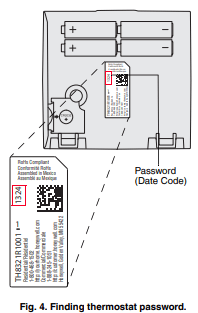
Finding Your Password (Date Code)
You will need the thermostat password to:
• Add or remove RedLINK accessories
• Make changes to Installer Setup
• Perform an Installer Test
• Reset Thermostat to Factory Default Settings
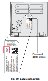
The password (date code) is located on the back of the thermostat (see Fig. 4)
You can also find the password (date code) by pressing MENU, selecting Dealer Information and then scrolling down to see the Date Code.
INSTALLATION OPTIONS
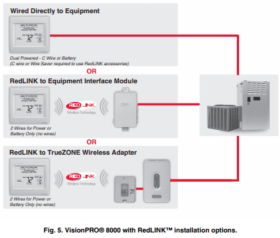
The VisionPRO® 8000 with RedLINK™ system can be wired directly to the equipment, used with an Equipment Interface Module, or with a TrueZONE wireless adapter.
If using the Equipment Interface Module, see “Installing Equipment Interface Module (if used)” on page 8.
If using a TrueZONE wireless adapter, follow the installation instructions that came with the TrueZONE panel, and go to “Selecting Thermostat Location” beginning on page 11.
* The relay outputs and inputs on the thermostat do not function when used with an Equipment Interface Module or the TrueZONE Wireless Adapter.
* If the thermostat has been setup WITHOUT an Equipment Interface Module or the TrueZONE Wireless Adapter and you would like to add one, you must reset the thermostat back to factory defaults. Press MENU > Installer Options > scroll down to select Reset to Defaults.
Guidelines for Installing RedLINK Devices
- When installing more than one Thermostat and Equipment Interface Module, mount the Equipment Interface Modules at least 2 feet apart for best RedLINK performance. No minimum distance is required between the Thermostats if the Thermostat is linked to an Equipment Interface Module.
- When the Thermostat is wired directly to the equipment (No Equipment Interface Module and No TrueZONE Wireless Adapter), mount the Thermostats at least 2 feet apart for best RedLINK performance.
- To determine if a RedLINK device will communicate properly in the installed location, during the connection process, press and quickly release the connect button on the RedLINK device at the desired mounting location. If the RedLINK device connects, then it will work reliably during normal operation. If the RedLINK device does NOT connect, try a new location. During the connection process, the signal is sent at low power and during normal operation the signal is sent at high power
- To connect a RedLINK device, make sure to press and quickly release the connect button on the RedLINK device. Press and holding the connect button down too long will not allow the device to connect
- If you link the Thermostat to the TrueZONE Wireless Adapter, you will NOT be able to do the following: control humidification, dehumidification or ventilation, setup a program schedule remotely from a computer, smart phone or tablet, work with the Wireless Indoor Sensor, Entry / Exit Remote or the Vent and Filter Boost Remote. To use these features, wire the Thermostat directly to the zone panel or use an Equipment Interface Module.
- If you are using a RedLINK device from a previous installation, you must reset the device first before you reconnect it to the new Thermostat/Equipment Interface Module. See page 116 for more information.
Installing Equipment Interface Module (if used)
If no Equipment Interface Module is used, skip to “Selecting Thermostat Location” beginning on page 11.
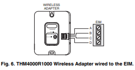
NOTE: If an EIM is mounted inside a metal cabinet, such as a commercial rooftop unit, it is recommended to use a THM4000R1000 Wireless Adapter for extended wireless range. Mount the Wireless Adapter outside the metal cabinet and connect to the ABCD terminals at the EIM. The Wireless Adapter functions as a remote antenna for the EIM. After it is wired to the EIM, it automatically takes over as the antenna for RedLINK communication. For best RedLINK performance, avoid mounting the Wireless Adapter above the roof deck or outside the exterior walls.
NOTE: If you install more than one thermostat and EIM, the EIMs must be at least 2 feet apart for best RedLINK performance.
The Equipment Interface Module (EIM) can be mounted vertically on the HVAC equipment or on a wall in the equipment room.
1. Mount the EIM near the HVAC equipment, or on the equipment itself. Use screws & anchors as appropriate for the mounting surface.
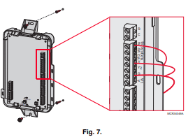
2. To wire the EIM, strip 1/4” insulation, then insert wires (see Fig. 7). For wiring diagrams, see “Wiring” beginning on page 117.
NOTE: Link EIM to thermostat BEFORE linking any RedLINK accessories. See “Linking RedLINK Accessories” on page 14.
3. If you are installing discharge and return air sensors, see “Selecting Discharge and Return Air Temperature Sensor Mounting Locations” beginning on page 9).
Wiring 24 Vac Common
- Single-Transformer System—Connect the common side of the transformer to the C screw terminal of the EIM. Leave the metal jumper wires in place between R, RC, and RH.
- Two-Transformer System—Connect the common side of the cooling transformer to the C screw terminal of the EIM. Remove the metal jumper wire between RC and RH. Connect the hot side of heating transformer to RH and leave the jumper wire between R and RC and connect the hot side of cooling transformer to R or RC.
POWER OPTIONAL REDLINK™ ACCESSORIES
Outdoor air sensor
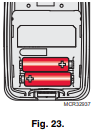
1. Install 2 fresh AA lithium batteries.
Portable Comfort Control
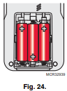
1. Install 3 fresh AA alkaline batteries.
Indoor air sensor
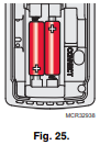
1. Install 2 fresh AAA alkaline batteries.
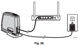
RedLINK™ Internet Gateway
1. Connect power cord to an electrical outlet not controlled by a wall switch.
2. Connect ethernet cable to router and the RedLINK Internet Gateway
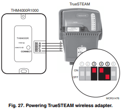
TrueSTEAM
1. Wire and power TrueSTEAM.
2. Connect the ABCD terminals between TrueSTEAM and the THM4000 Wireless Adapter.
3. Adjust the DIP Switches on TrueSTEAM as follows when using the Wireless Adapter:
• DIP3: UP
• DIP4: UP
• DIP5: DOWN
Entry/Exit Remote or Vent Boost Remote
1. Remove the cover.
2. Insert the CR2450 coin cell battery (included) into the slot at the bottom of the remote. See polarity marking on the remote.
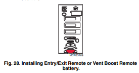
3. The LED will briefly flash green. If it flashes red, battery is not good.
NOTE: If the thermostat is wired directly to the equipment, 24 VAC (C wire) is required to connect RedLINK accessories. Turn on 24 VAC before performing the initial setup.
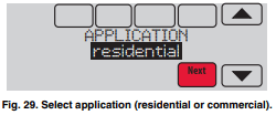
Initial setup options define the type of system you are installing:
- Residential or commercial
- Non-zoned or zoned
- Used with or without an Equipment Interface Module (THM5421)
- Used with or without the TrueZONE Wireless Adapter (THM4000)
1. Follow prompts on the screen to select the appropriate options.
NOTE: If you are connecting the thermostat to the TrueZONE Wireless Adapter (THM4000), refer to the TrueZONE instructions to link the thermostat and RedLINK accessories.
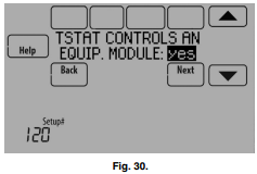
Linking Thermostat to Equipment Interface Module (if used)
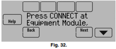
1. In thermostat setup, when you are prompted to answer TSTAT CONTROLS AN EQUIP. MODULE: select yes, then press Next.
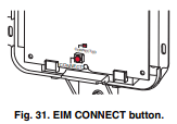
2. Press and quickly release the CONNECT button on the EIM. Make sure the “Connected” light is flashing green.
NOTE: If the “Connected” light does NOT flash green, another system may be in the listening mode. Please exit the listening mode at the other system and then try again.
Green Flashing: In Listening Mode - system is ready to add RedLINK devices.
Green Steady: RedLINK devices are communicating.
Red: RedLINK device(s) are NOT communicating. Check EIM and RedLINK devices.
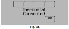
3. While the “Connected” light is flashing green on the EIM, press Next on the thermostat. After a short delay, the screen will show the thermostat is connected.
4. Press Next, as directed on screen, to link RedLINK accessories.
Linking RedLINK Accessories
1. When you see the prompt Connect RedLINK Accessories?, touch No or Yes.
a. If you select No, continue to step 5.
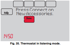
b. If you select Yes, you will be prompted to Press Connect on New Accessories. Continue to step 2.

NOTE: Accessories must be at least 2 feet away from the thermostat or EIM during the linking process.
2. While the Press Connect message is displayed (listening mode), press and quickly release the CONNECT button on each new RedLINK accessory.
NOTE: For locations of CONNECT buttons on RedLINK accessories, see “Locating the Connect Buttons on RedLINK Accessories” beginning on page 16.
3. After a short delay (up to 15 seconds), check thermostat to confirm the connection of each RedLINK accessory. Touch  or
or  to review the list.
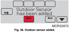
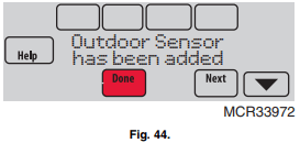
4. Touch Done at the thermostat after all new RedLINK accessories are connected.
NOTE: Thermostat displays a countdown timer while in the listening mode. If it detects no activity for 15 minutes, it exits listening mode.
Completing Initial Setup
5. Finish the setup by selecting the desired options. Touch Done after you select the last option you want to change.
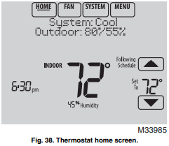
The thermostat now displays its Home screen and the thermostat setup is complete.
Adding RedLINK Accessories to the Thermostat
If you want to add RedLINK accessories after the thermostat has been setup, follow these steps.
1. Touch Menu.
2. Select Installer Options.
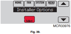
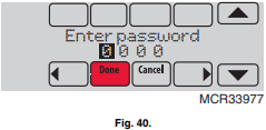
3. Enter password (date code) and touch Done. See “Finding Your Password (Date Code) to Access Installer Options” beginning on page 19 for more information.
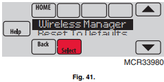
4. Select Wireless Manager.
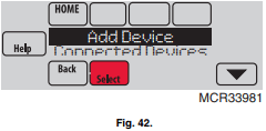
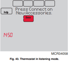
5. Select Add Device. The screen displays “Press Connect on New Accessories.” The thermostat is now in listening mode.
NOTE: Accessories must be at least 2 feet away from the thermostat or EIM during the linking process.
6. Press and quickly release the CONNECT button on each new RedLINK accessory.
NOTE: For locations of CONNECT buttons on RedLINK accessories, see “Locating the Connect Buttons on RedLINK Accessories” beginning on page 16.
7. After a short delay (up to 15 seconds), check thermostat to confirm the connection of each RedLINK accessory. Touch or to review the list.
8. Touch Done at the thermostat after all new RedLINK accessories are connected.
NOTE: Thermostat displays a count-down timer while in the listening mode. If it detects no activity for 15 minutes, it exits listening mode.
Finding Your Password (Date Code) to Access Installer Options
You need a password (Date Code) to access Installer Options. Installer Options allow you to:
- Make changes to the Installer Setup.
- Perform an Installer Test.
- Add, remove, rename or view connected RedLINK accessories.
- Reset the thermostat to Factory Default settings.
The password (Date Code) is located on the back of the thermostat. It can also be found by following these steps:
1. Touch Menu.
2. Select Dealer Information.
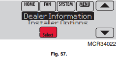
3. Scroll down to see the Date Code.
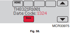
Thermostat Password (Date Code)
The following options are available when you access Installer Options. For more information on each, press Help on the thermostat.
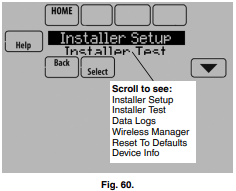
Installer Options.
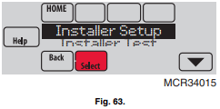
Installer Setup
- Select INSTALLER SETUP to set system settings one by one
Installer Test
- Select INSTALLER TEST to quickly determine if the heat, cool, fan and thermostat are operating properly. Minimum off timers are ignored during the test.
Data Logs
- Select DATA LOGS to turn off/on the Alerts Log or Interaction Log.
Wireless Manager
- Select WIRELESS MANAGER to add, remove, rename or view the connected wireless accessories.
Reset To Defaults
- Select RESET TO DEFAULTS to place all thermostat settings back to the factory settings.
- Note: If the thermostat has been setup WITHOUT an Equipment Interface Module or the TrueZONE Wireless Adapter and you would like to add one, you must reset the thermostat back to factory defaults.
Device Info
NOTE: You can use the thermostat microSD port to download all Installer Setup settings, including your company name and contact information. You can upload this data to each thermostat you install, to save time.
Make Changes to Installer Setup
NOTE: Use a microSD card to save set up time. See “To Use the MicroSD Card in the Thermostat” on page 101.
1. Touch Menu.
2. Select Installer Options.

3. Enter password (date code) and touch Done. See “Finding Your Password (Date Code) to Access Installer Options” beginning on page 19 for more information.

4. Select Installer Setup
5. Follow prompts on the screen to select the desired setup options. See Table 2 for Installer Setup options.
INSTALLER TESTS
Accessing Installer Tests
1. Press MENU on the home screen, then scroll down to Installer Options and press SELECT.
2. Enter the password (date code) when prompted. See “Finding Your Password (Date Code) to Access Installer Options” beginning on page 19 for more information.
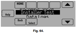
3. Scroll down to Installer Test and press SELECT.
4. Select Equipment Test or Wireless Test.
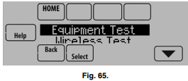
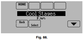
Using the Equipment Test
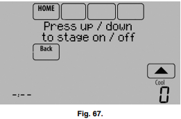
1. Select the equipment you want to test and press the arrow buttons to turn the equipment on/off. Press Back to test the remaining equipment.
NOTE: The time out for the Equipment Test mode is 30 minutes (if there is no keypress for 30 minutes, the thermostat will automatically exit the Equipment Test).
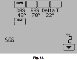
2. Run Time, Discharge, Return and Delta T data are displayed for heating and cooling tests (requires Discharge and Return Air Sensors). See Fig. 68. The Discharge, Return and Delta T are updated every 30 seconds during the test. The Run Time counter starts over when the next stage is turned on.
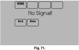
Using the Wireless Signal Strength Test
1. Select Installer Test (see Fig. 64), then select Wireless Test.
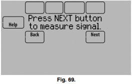
2. Press Next to measure the signal strength. After a brief pause, the thermostat will display test results.
3. A number from 5-10 means communication is good.
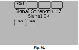
4. If the screen displays “No Signal,” move the thermostat to a different location and test again.
Entry/Exit Remote or Vent Boost Remote
Mounting the remote is optional.
1. Remove the front cover from the remote.
2. Use provided screws and wall anchors to fasten the remote to the wall. Drill 3/16-inch holes for drywall, 7/32- inch for plaster.
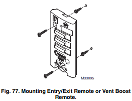
3. Replace the cover on the remote.
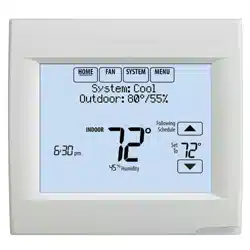
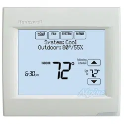
OPERATION
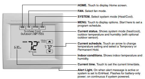
Fig. 78. Quick reference to residential display.
NOTE: The screen lights when you press any button. After you complete your changes, the screen stays lit for 16 seconds if the thermostat is battery powered only or it stays lit for 45 seconds if the thermostat is system powered (C wire). Depending on how your thermostat was installed, the screen light may always be on.
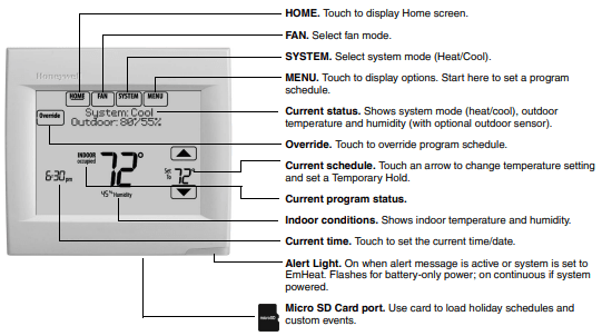
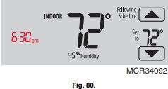
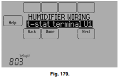
Fig. 79. Quick reference to commercial display.
NOTE: The screen lights when you press any button. After you complete your changes, the screen stays lit for 16 seconds if the thermostat is battery powered only or it stays lit for 45 seconds if the thermostat is system powered (C wire). Depending on how your thermostat was installed, the screen light may always be on.
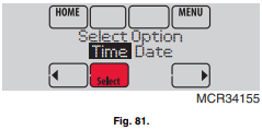
Setting the Time/Date
1. Touch the current time. The screen displays Select Option.
2. Touch Time or Date, then touch Select.
3. Touch  or
or  until the proper time/date is displayed. 4. Touch Done to save or Cancel to ignore changes.
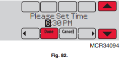
5. Touch Home to redisplay the Home screen.
NOTE: The date is not shown on the home screen; however, it should be set to allow the thermostat to adjust time automatically for daylight saving time and for other features such as vacation hold.
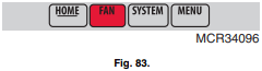
Setting the Fan
1. Touch FAN to display fan settings.
2. Touch On, Auto, Circ, or Follow Schedule.
3. Touch Done to save and exit.
- On: Fan is always on.
- Auto: Fan runs only when heating or cooling system is on.
- Circ: Fan runs randomly, about 35% of the time (residential only).
- Follow Schedule: Fan controlled by program.
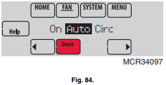
NOTE: In commercial use, touch Auto or On to temporarily override the programmed fan schedule.
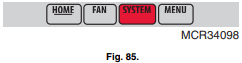
Setting System Mode
1. Touch SYSTEM to display system settings.
2. Touch desired option
- Heat: Controls only the heating system.
- Cool: Controls only the cooling system.
- Off: Heating/cooling systems are off.
- Auto: Selects heating or cooling depending on the indoor temperature.
- Em Heat (heat pumps with aux. heat): Controls auxiliary/emergency heat. Compressor is locked out.
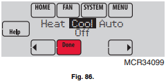
3. Touch Done to save and exit.
NOTE: The Auto and Em Heat system settings may not appear, depending on how your thermostat was installed.
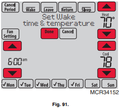
Adjusting Program Schedules
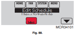
1. Touch MENU.
2. Select Edit Schedule to display Use Scheduling Assistant?
- Touch Yes to create a schedule by answering simple questions.
- Touch No to manually create a program schedule.
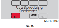
NOTE: To reduce costs, use the “Preset Energy-Saving Schedules” on page 62.
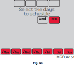
3. Select the days to schedule, touch Next.
4. Touch  or
or  to set your Wake time for selected day(s).
5. Touch or to set Heat and Cool temperatures for the Wake period.
6. Touch other time periods (Leave, Return, Sleep) to set time and temperatures for each.
7. Touch Done to save and exit (Touch Cancel to exit without saving changes).
NOTE:
- Touch Cancel Period to eliminate any unwanted time period.
- Touch Fan Setting to customize fan settings for any time period.
Overriding Schedules: Residential Use
1. Touch or to adjust the temperature (right side of screen) and the Hold Until time (left side). The schedule will resume when the Hold Until time expires.
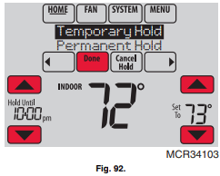
2. Select Permanent Hold to keep the same temperature until you change it or resume the program schedule.
Touch Cancel Hold at any time to resume the program schedule.
Overriding Schedules: Commercial Use
Touch or to adjust the temperature. It will be maintained until the hold time you set.
- To change the hold time, touch the Hold Until arrow buttons. This time can be adjusted up to the maximum time set by the installer.
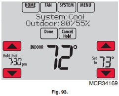
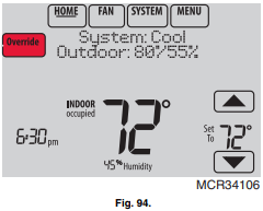
- Touch Override to use a pre-set occupied temperature if a person uses the room during an unoccupied period. The new temperature will be maintained for 1 hour and can be adjusted up to the maximum time set by the installer.
The programmed schedule will resume when the override timer expires. Touch Cancel Hold at any time to resume the program schedule.
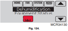
Adjusting Dehumidification Settings: Residential Use
This feature can control a dehumidifier or use your air conditioner to reduce humidity.
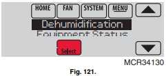
1. Touch MENU and select Dehumidification
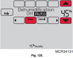
2. Select Auto.
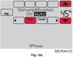
3. Touch or to select humidity level.
4. Touch Done to save your settings. Touch Cancel to ignore changes.
NOTE: If your air conditioner is used to control humidity, the temperature may drop up to 3° F below your temperature setting until humidity reaches the desired level.
Adjusting Dehumidification Settings: Commercial Use
This feature can control a dehumidifier or use your air conditioner to reduce humidity.
1. Touch MENU and select Dehumidification.
2. Select Auto
3. Touch or to select humidity level.
4. Touch Done to save your settings. Touch Cancel to ignore changes.
If your air conditioner is used to control humidity, the thermostat may use the following methods to maintain humidity:
- Cool from 1° to 5° F lower than your temperature setting.
- Run cooling for the minimum “on” time to reduce humidity.
- Run cooling and heating at the same time to reduce humidity without lowering the temperature.
Adjusting Ventilation Settings
1. Touch MENU, and select Ventilation.
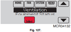
2. Select Mode, Temporary Boost, or Lockout, then select appropriate options.
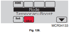
3. Touch Done to save your settings. Touch Cancel to ignore changes.
Ventilation Options
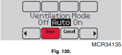
Mode:
- Auto: Ventilation runs as programmed by the installer.
- Off: Ventilation remains off unless turned on using the timer.
- On: Ventilation is always on.
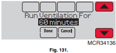
Temporary Boost: Touch or to select how long to run ventilation temporarily. To turn it off, set it to zero.
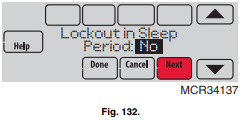
Lockout: Touch or to select Yes or No, then touch Next. Select Yes to prevent ventilation from running during the Sleep or Unoccupied (commercial) program periods or when outdoor conditions exceed values set by the installer.
Dry Contact Alerts
A Dry Contact device such as a wet switch can be connected to the S1, S2, S3 or S4 terminals at the Equipment Interface Module.
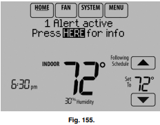
When the dry contact device detects a problem, the thermostat displays an alert on the home screen. When the user touches Press HERE for info on the Home Screen, the alert message will be displayed.
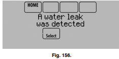
Pressing Select displays options for addressing the Alert message:
- View More Info
- Remind Me Later
- Dismiss
- View Dealer Info
To clear the Alert, (and turn off the Red Alert Light on the thermostat), select Dismiss.
The following dry contact alerts are available.
Full Drain Pan Alert
When the dry contact device detects that the condensate drain pan is full, the thermostat provides an alert to the user.
NOTE: If you want the compressor to turn off when the drain pan is full, wire the system so the dry contact device turns off the compressor when the drain pan is full.
Dirty Filter Alert
When the dry contact device detects a dirty air filter (pressure drop across the filter), the thermostat provides an alert to the user to replace the filter.
Water Leak Alert
When the dry contact device detects a water leak, the thermostat provides an alert to the user.
System Shutdown Alert
When the dry contact device detects a critical problem with the system, the thermostat provides an alert to the user indicating that the system was shut down.
When the dry contact device detects a problem with the system (for example, smoke detection), the thermostat will not call for heating, cooling, fan or IAQ equipment until the dry contact is deactivated or the feature is unconfigured at the thermostat.
Service Needed Alert
When the dry contact device detects an issue that requires service, the thermostat provides an alert to the user.
Fan Failure Alert
The Fan Failure Alert protects the equipment when there is no airflow. When the dry contact device (for example, sail switch) detects no air flow for 5 minutes after a call for forced air heat, cool, or fan, the thermostat provides an alert to the user indicating that the system was shut down due to a lack of airflow.
The thermostat will call for the fan and lockout all other equipment until the dry contact device senses air flow again or the feature is unconfigured at the thermostat.
Custom Alert
Allows the dealer to enter a custom alert to be displayed when a dry contact device is activated. For example, a float switch can detect when your sump pump is not working.
Set Up the Dry Contact Alerts
You can connect the S1, S2, S3 and S4 terminals on the EIM to a dry contact device to display an alert. Dry contact alerts include Full Drain Pan, Dirty Filter, Water Leak, System Shutdown, Service Needed, Fan Failure and Custom Alert. Dry contact device can be normally open (shown in diagram) or normally closed.
IMPORTANT The dry contact device must be rated for low voltage.
NOTE: You can connect multiple Dry Contact devices in parallel to the S1, S2, S3 or S4 terminals.
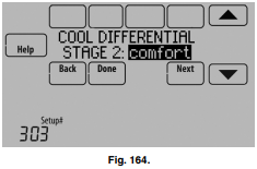
TO CHANGE DIFFERENTIAL SETTINGS
1. Select Advanced Options to view/adjust differentials between all stages.
2. Default is Comfort. Adjust differentials as needed.
Backup Heat Droop
A Backup Heat Droop is available for any system with 2 heating types. For example:
- Heat Pumps with any type of Backup Heat
- Radiant Heat with any type of Backup Heat
- Hot Water Fan Coil with any type of Backup Heat
The Backup Heat Droop restricts backup heat during the following conditions:
- Normal Operation
- Manual Setpoint Changes
The options are:
- Comfort – keeps temperature within 1 degree of the setpoint.
- 2 to 15 °F – Backup heat is not used unless the indoor temperature drops to the selected Backup Heat Droop. For example, if the Backup Heat Droop is set to 2 °F (1.0 °C), the indoor temperature must be 2 °F (1.0 °C) away from the setpoint before the backup heat turns on.
NORMAL OPERATION
When the Backup Heat Droop is set to Comfort, the thermostat uses backup heat as needed to keep the indoor temperature within 1 °F (0.5 °C) of the setpoint. The Comfort setting is NOT an option on heat pumps with fossil fuel backup heat.
When the Backup Heat Droop is set to 2 °F or higher, backup heat is not used unless the indoor temperature drops to the Backup Heat Droop setting or the Backup Heat Upstage Timer expires, whichever occurs first. The upstage timer starts when the highest stage of the previous equipment type turns on.
MANUAL TEMPERATURE CHANGE
When the Backup Heat Droop is set to Comfort, the thermostat uses backup heat as needed to keep the indoor temperature within 1 °F (0.5 °C) of the setpoint. The Comfort setting is NOT an option on heat pumps with fossil fuel backup heat.
When the Backup Heat Droop is set to 2 °F or higher, if the primary heat is making progress as expected, backup heat will not be used to reach the new setpoint. Set to a higher number to use less backup heat (a greater difference between the current indoor temperature and the new setpoint is required to turn on backup heat). See notes below.
PROGRAMMED RECOVERY
If the primary heat is making progress as expected, backup heat will not be used to reach the setpoint of the next program period. Backup heat is always restricted during a programmed recovery when the Adaptive Intelligent Recovery feature is used. See note below.
NOTE: During a programmed recovery (or when the temperature setpoint is changed by the user), the thermostat waits to turn on the backup heat depending on system performance, load conditions and how many degrees the temperature setpoint is changed. Backup heat will be used ONLY when the temperature is not rising quickly enough to reach the setpoint in a reasonable time.
NOTE: If the backup heat was used in the last 2 hours because the primary heat was not able to maintain the setpoint, the thermostat may turn on the backup heat earlier when the user raises the setpoint. This does NOT apply to heat pumps with fossil fuel backup heat.
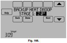
TO CHANGE BACKUP HEAT DROOP SETTINGS
1. Select Basic Options or Advanced Options to view/adjust Backup Heat Droop settings.
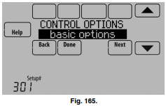
2. Default is Comfort. Adjust differentials as needed.
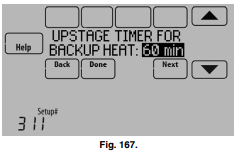
Backup Heat Upstage Timer
The Backup Heat Upstage Timer is available for any system with 2 heating types and the Backup Heat Droop is set to 2 °F (1.0 °C) or higher
Backup heat is not used unless the indoor temperature drops to the Backup Heat Droop setting or the Backup Heat Upstage Timer expires, whichever occurs first. The upstage timer starts when the highest stage of the previous equipment type turns on
Backup Heat Upstage Timer options are Off, 30 minutes to 16 hours. Default is Off.
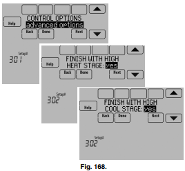
Multistage Control
Multistage Control keeps the high stage of the equipment running until the desired setpoint is reached. This setting is recommended for Geothermal Heat Pumps to allow the loop to rest.
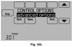
To view/adjust “Finish with High Heat Stage” or “Finish with High Cool Stage,” set ISU 301 Control Options to “Advanced Options.” See Fig. 168. Select Yes to turn on this feature. Default is No.
INDOOR AIR QUALITY (IAQ) CONTROL
Humidification
The thermostat reads the indoor humidity level and allows the user to set a humidification setting with or without window protection.
The thermostat can be set up to control a humidifier in any system mode in the Installer Setup (ISU 806). A discharge air sensor is required to humidify in the cool mode.
If humidification and dehumidification are setup to operate in the same system mode (Heat, Cool, Off) and you are sensing humidity from one location, the thermostat will automatically enforce a 15% deadband between the humidification and dehumidification settings. The thermostat will automatically switch between humidification and dehumidification to maintain the desired humidity level.
If humidification and dehumidification are setup to operate in the same system mode (Heat, Cool, Off) and you are sensing humidity from two different locations using a remote wireless indoor sensor, the thermostat will allow humidification and dehumidification to operate at the same time, and there is no deadband between humidification and dehumidification settings.
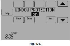
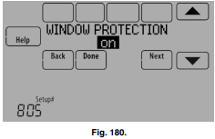
Window Protection
Window Protection limits the amount of humidity to prevent frost or condensation on windows. Window Protection (ISU 805) requires an outdoor sensor.
The thermostat prevents frost or condensation on windows by not allowing the humidifier to run above a certain level. To prevent frost or condensation, the thermostat may turn off the humidifier before the humidity setting is reached.
To adjust the Window Protection setting, press MENU, scroll down and select Window Protection. Window Protection is set on a scale from 1-10. A setting of "1" represents poorly insulated windows and a setting of "10" represents well insulated windows. A lower number automatically reduces the humidity to help prevent frost or condensation on your windows. Use a higher number if indoor air seems too dry. To prevent frost/condensation on your windows during cold outdoor temperatures, poorly insulated windows require a lower Window Protection setting, which will limit how much your humidifier can run.
After you set the Window Protection setting, check for frost/ condensation on your windows in the morning. If frost/ condensation is present, adjust the Window Protection setting to the next lowest number and check for frost/condensation on your windows the next morning. Continue to adjust the Window Protection setting to a lower number until frost/condensation is no longer present.
If Window Protection is turned Off, the thermostat controls the humidity level to the user's desired humidity setting. Frost or condensation may appear on windows.
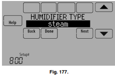
Set up Humidification
1. Select the Humidifier Type at ISU 800. See Fig. 177.
NOTE: Based on the humidifier type you select, the thermostat defaults to the most commonly used settings for that humidifier type.
For example, a Bypass or Fan Powered humidifier will default ISU 807 to “Hum when Heat is On.”
A Steam humidifier will default ISU 807 to "Tstat Controls Fan."
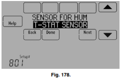
2. If optional remote wireless indoor sensors are installed, you can choose which sensor you want to use for humidification control. You can use a different sensor for dehumidification. See “Wireless Indoor Sensor” beginning on page 113 for more information.
3. Select the terminals wired to the humidifier. See Fig. 179.
NOTE: U1, U2, and U3 are Normally Open Dry Contacts that require power from the system transformer or a separate transformer. See “Wiring IAQ Equipment or a Heat/Cool Stage to the Universal Terminals” beginning on page 129.
4. Set Window Protection setting. See Fig. 180.
NOTE: Outdoor sensor is required for Window Protection.
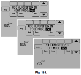
5. Select the system mode(s) to allow humidification. See Fig. 181.
NOTE:
Heat includes Heat, Emergency Heat and Auto. If the system is in Auto mode, the thermostat will allow humidification if the last call was for heat.
Cool includes Cool and Auto. If the system is in Auto mode, the thermostat will allow humidification if the last call was for cool. A discharge sensor is required to humidify in the Cool mode. The thermostat prevents condensation in the duct work by not allowing the humidifier to run when the discharge temperature goes below the dew point temperature. The humidifier is allowed to run again after the discharge temperature rises above the dew point temperature.
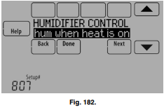
6. Select from one of the Humidification Control Options (ISU 807). See Fig. 182.
- Hum when Heat is On: The thermostat turns on the humidifier only if the heat is currently running and humidification is needed.
- Hum when Fan is On: The thermostat turns on the humidifier only if the fan is currently running and humidification is needed.
- Tstat Controls Fan: The thermostat turns on the humidifier and the fan when humidification is needed.
- Hum Controls Fan: The thermostat turns on the humidifier when humidification is needed and the humidifier controls the fan.
7. Set the desired lockout option. See Fig. 183.
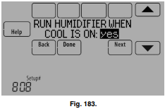
NOTE: ISU 1014 gives the option to lockout ventilation during calls for humidification. This helps maintain the desired humidity level.
OPTIONAL ACCESSORIES
PORTABLE COMFORT CONTROL
If you have only one thermostat, you move this remote control from room to room (like a portable thermostat), to make sure the temperature is comfortable in the room you’re using. If you have multiple thermostats, you can view and adjust the temperature in each room from your armchair. A Portable Comfort Control can control up to 16 thermostats.

WIRELESS OUTDOOR SENSOR
With a wireless outdoor sensor, your VisionPRO® thermostat can display outside temperature and humidity. This information can also be displayed on your handheld Portable Comfort Control.

WIRELESS INDOOR SENSOR
If an indoor sensor is installed, your VisionPRO thermostat will respond to temperature and humidity readings at the sensor location—providing comfort where the sensor is located. With multiple sensors, the thermostat can average temperature readings from each, to optimize comfort throughout your home. The thermostat can be used with up to 6 Wireless Indoor Sensors.

REDLINK™ INTERNET GATEWAY
The Honeywell RedLINK Internet Gateway gives you remote access to your VisionPRO® thermostat from the web, smart phone or tablet. You can view or adjust indoor temperature, system mode and other settings. The Gateway can also send alerts to as many as 6 email addresses to notify you if a problem occurs.

WIRELESS ENTRY/EXIT REMOTE
This device mounts beside your door for one-touch control. Press AWAY to control to an energy saving temperature when you leave home. Press HOME to control to a comfortable temperature when you return. To change pre-set temperatures, go to MENU > Entry/ Exit Remote. Two covers are sold with the device that allow it to be used in residential or commercial applications. The Residential cover is labeled HOME, AWAY and VACATION and the Commercial cover is labeled OCCUPIED, UNOCCUPIED and HOLIDAY. The thermostat can be used with up to 3 Entry/Exit remotes. Each Entry/Exit remote can control up to 16 thermostats.

WIRELESS VENT AND FILTER BOOST REMOTE
This device mounts anywhere in your home (typically bathroom or kitchen) for convenient, on-demand ventilation. Select 20, 40 or 60 minutes for increased ventilation. The thermostat can be used with up to 6 Vent Boost remotes.
PORTABLE COMFORT CONTROL
The Portable Comfort Control communicates wirelessly with the thermostat, and can control up to 16 thermostats.
NOTE: Each thermostat can only be connected to 1 Portable Comfort Control.
If you have one thermostat, you move this remote control from room to room (like a portable thermostat), to make sure the temperature is comfortable in the room you’re using. If you have multiple thermostats, you can view and adjust the temperature in each room from the Portable Comfort Control.
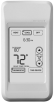
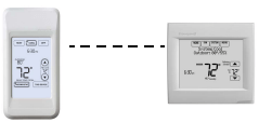
If you have one thermostat, temperature is measured at the thermostat (Fig. 302) or Portable Comfort Control (Fig. 303), as you choose.
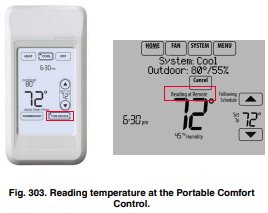
If the thermostat is being averaged with remote indoor sensors, and you select THERMOSTAT on the Portable Comfort Control, you will see the temperature average from the remote indoor sensors and the thermostat.
NOTE: If the thermostat is not part of the temperature average, then you will only see the temperature average from the remote indoor sensors when you select THERMOSTAT on the Portable Comfort Control.
If the thermostat is being averaged with remote indoor sensors, and you select THIS DEVICE on the Portable Comfort Control, you will see the temperature measured at the Portable Comfort Control only.
If you have multiple thermostats, temperature is measured at each thermostat. Press the TOGGLE ZONE arrows to choose which room to display and adjust. See Fig. 304.
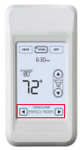
Fig. 304. Portable Comfort Control used with Multiple Thermostats. Temperature is measured at each thermostat.
REMOTE INDOOR SENSORS
For installation, see “C7189R1004 Wireless Indoor Sensor” on page 59, and “C7189U1005 Wired Indoor Sensor” on page 59. For wiring, see “Wiring guide — Wired Indoor Sensors” on page 135.
Indoor Sensor Operation
Temperature Control
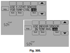
The thermostat can be set to respond to its internal temperature sensor, or to an optional remote indoor sensor. If multiple sensors are used, the thermostat will average the temperature detected at each sensor.
In Fig. 305, both the thermostat internal sensor and remote indoor sensor are being used for Temperature Control and are being averaged since both sensors are set to “Yes.” Select “No” if you do NOT want a specific sensor to be used for temperature control or be part of the temperature average.
When using multiple remote indoor sensors, you should name each sensor after you link it to the thermostat. See “Wireless Indoor Sensor” beginning on page 18 for more information. Naming the sensors allows you to select the appropriate sensor(s) for Temperature Control in the Installer Setup
Humidification control
If optional remote indoor sensors are installed, you can choose which sensor you want to use for humidification control. You can use a different sensor for dehumidification.
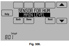
When using multiple remote indoor sensors, you should name each sensor after you link them to the thermostat. See “Wireless Indoor Sensor” beginning on page 18 for more information. Naming the sensors allows you to select the appropriate sensor for Humidification Control in the Installer Setup. For example, in Fig. 306, the MAIN LEVEL remote indoor sensor is selected for Humidification Control.
NOTE: Requires wireless indoor sensor. Humidity sensing can not be averaged.
Dehumidification control
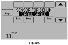
If optional remote indoor sensors are installed, you can choose which sensor you want to use for dehumidification control. For example, you can use one sensor for humidification control, and another for dehumidification.
When using multiple remote indoor sensors, you should name each sensor after you link them to the thermostat. See “Wireless Indoor Sensor” beginning on page 18 for more information. Naming the sensors allows you to select the appropriate sensor for Dehumidification Control in the Installer Setup. For example, in Fig. 307, the CRAWL SPACE remote indoor sensor is selected for Dehumidification Control.
NOTE: Requires wireless indoor sensor. Humidity sensing can not be averaged.
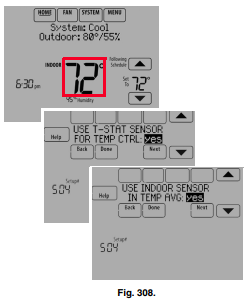
Temperature Display
The temperature reading displayed on the home screen is from the sensor or sensors that are being used for temperature control.
In Fig. 308, the temperature reading is the average of the thermostat internal sensor and the remote indoor sensor.
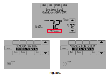
Humidity Display
If you are sensing Humidity from one location (internal or remote), the humidity reading displayed on the home screen is from the sensor that is being used for control. In Fig. 309, the humidity reading is from the remote indoor sensor.
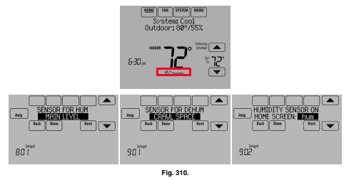
If you are sensing Humidity from two separate locations (one for humidification and another for dehumidification), you can select which humidity reading to display on the home screen. In Fig. 310, the humidity reading is from the Main Level remote indoor sensor based on the setting in ISU.
Backup Control
This section explains when backup control is used. For example, if batteries in the wireless indoor sensors are depleted.
If the Thermostat is Part of the Temperature Average
- The thermostat controls the system using the remaining sensors that are part of the temperature average.
- If there are no remote indoor sensors remaining, the thermostat controls the system using its internal sensor.
- If the internal thermostat sensor is not available and a Return Air Sensor is connected, the Backup Control in the EIM is used. The backup control maintains 55 °F in heat, 85 °F in cool and operates the fan continuously to sense and control temperature.
If the Thermostat is NOT Part of the Temperature Average
- The thermostat controls the system using the remaining sensors that are part of the temperature average.
- If there are no remote indoor sensors remaining and a Return Air Sensor is connected, the Backup Control in the EIM is used. The backup control maintains 55 °F in heat, 85 °F in cool and operates the fan continuously to sense and control temperature.
REPLACING A THERMOSTAT
When you replace a thermostat, you must reset the RedLINK accessories before connecting them to the new thermostat.
Follow the instructions below:
At the Equipment Interface Module (EIM)
1. Press and hold the CONNECT button on the EIM until the CONNECTED LED glows amber (hold for about 10 seconds).
2. Follow the prompts on the screen to connect the new thermostat to the EIM. See page 14.
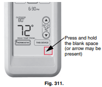
At the Portable Comfort Control
1. Press and hold the blank space (or arrow) in the lower right hand corner of the screen until the display changes (hold for about 4 seconds).
2. Press REMOVE, then YES to disconnect from the old thermostats.
3. To reconnect the thermostat, go to “Linking RedLINK Accessories” beginning on page 14.
At the Indoor Sensor, RedLINK Internet Gateway, Entry/Exit Remote, Vent-Filter Boost Remote or TrueSTEAM Wireless Adapter
1. Press and hold the CONNECT button on the accessory until the status light glows amber (hold for about 10 seconds).
2. To reconnect the thermostat, go to “Linking RedLINK Accessories” beginning on page 14.
REPLACING AN EQUIPMENT INTERFACE MODULE
When you replace an EIM, you must reset the RedLINK accessories before connecting them to the new thermostat.
Follow the instructions below:
At the thermostat
- Press MENU, scroll down and select Installer Options, enter the password (Date Code) when prompted, scroll down and select Wireless Manager, scroll down and select Remove Device, then select This Thermostat.
- Follow the prompts on the screen to connect the thermostat to the new EIM.
At the Portable Comfort Control
- Press and hold the blank space (or arrow) in the lower right hand corner of the screen until the display changes (hold for about 4 seconds). See Fig. 311.
- Press REMOVE, then YES to disconnect from the old thermostats. To reconnect the thermostat, go to “Linking RedLINK Accessories” beginning on page 14.
At the Indoor Sensor, RedLINK Internet Gateway, Entry/Exit Remote, Vent-Filter Boost Remote or TrueSTEAM Wireless Adapter
1. Press and hold the CONNECT button on the accessory until the status light glows amber (hold for about 10 seconds).
2. To reconnect the thermostat, go to “Linking RedLINK Accessories” beginning on page 14.
Zoning FAQs
Q: How does the RedLINK VisionPRO thermostat control a humidifier in zoned systems?
A: If ISU 807 Humidifier Control is set to Tstat Controls Fan, then the zone panel will close the dampers for the other zones with a call for humidification.
If ISU 807 Humidifier Control is set to Hum Controls Fan, then all dampers will be open with a call for humidification (unless another zone is calling for heat, cool or fan at that time). See Fig. 348.
Q: How does the RedLINK VisionPRO thermostat control a ventilator in zoned systems?
A: If ISU 1006 Vent Fan Control is set to Tstat Controls Fan, then the zone panel will close the dampers for the other zones with a call for ventilation.
If ISU 1006 Vent Fan Control is set to Equip Controls Fan, then all dampers will be open with a call for ventilation (unless another zone is calling for heat, cool or fan at that time). See Fig. 349.
Q: How does the RedLINK VisionPRO thermostat control a dehumidifier in zoned systems?
A: If ISU 913 Dehum Fan Control is set to Tstat Controls Fan, then the zone panel will close the dampers for the other zones with a call for dehumidification.
If ISU 913 Dehum Fan Control is set to Equip Controls Fan, then all dampers will be open with a call for dehumidification (unless another zone is calling for heat, cool or fan at that time). See Fig. 350.
Q: Will the RedLINK VisionPRO thermostat work with a zone panel?
A: It depends on the zone panel:
HZ322 or HZ432 (without an add-a-zone): If you have an HZ322 or HZ432 on a 2-4 zone system and you are not going to control a humidifier, dehumidifier, or ventilator with the thermostat, you can use a THM4000R1000 wireless adapter with the zone panel and connect the RedLINK VisionPRO thermostat as one of the zones. A single THM4000R1000 wireless adapter allows you to connect up to three RedLINK VisionPRO thermostats with an HZ322 or up to four RedLINK VisionPRO thermostats with an HZ432.
HZ432 (with a TAZ-4 add-a-zone): You cannot use a wireless adapter when a TAZ-4 is used. Each RedLINK VisionPRO thermostat used would need a separate THM5421R Equipment Interface Module or you can wire the RedLINK VisionPRO directly to the zone panel. The Equipment Interface Module would wire to the zone it is controlling on the HZ432 or TAZ-4.
Zone panel with no master or slave: As long as all zones on the zone panel are wired the same and they use typical terminals with an R and C plus Y, G, etc, the RedLINK VisionPRO thermostat should work. Each RedLINK VisionPRO thermostat used would need a separate THM5421R Equipment Interface Module or you can wire the RedLINK VisionPRO directly to the zone panel. The Equipment Interface Module would wire to the zone it is controlling on the zone panel.
Master zone: A master uses separate O and B wires. The RedLINK VisionPRO thermostat cannot be used as a master thermostat.
Q: Can I use the remote indoor sensors with the RedLINK VisionPRO thermostats if I have zoning?
A: It depends. The RedLINK VisionPRO thermostats can only control 1 zone, even if it is used with multiple sensors. The RedLINK VisionPRO thermostat cannot be used with a remote sensor if it is used with a THM4000R adapter. The RedLINK VisionPRO thermostat can be used with a remote sensor if it is used with a THM5421R Equipment Interface Module or if the thermostat is wired directly to the panel.
Q: Can I use a telephone access module with the RedLINK VisionPRO thermostat?
A: No. The telephone access module only works with the TH9421C or TH5320C communicating thermostats and the EIM or zone panel used with those controls. See the Gateway section for information on using RedLINK VisionPRO thermostats with a THM6000R Gateway for Internet access.
TROUBLESHOOTING
Screen is blank
- Check circuit breaker and reset if necessary.
- Make sure power switch at heating and cooling system is on.
- Make sure furnace door is closed securely.
- If thermostat is battery powered, make sure fresh AA alkaline batteries are installed correctly.
Screen is difficult to read
- Change screen brightness using Preferences menu.
Red light is on
- If thermostat is in Emergency Heat mode, the red light is normal. It shows that the thermostat is in Emergency Heat mode.
- If thermostat is not in Emergency Heat mode, an alert is active. Check message on the thermostat screen.
Heating or cooling system does not respond
- Touch SYSTEM to set system to Heat. Make sure the temperature is set higher than the Inside temperature.
- Touch SYSTEM to set system to Cool. Make sure the temperature is set lower than the Inside temperature.
- Check circuit breaker and reset if necessary.
- Make sure power switch at heating & cooling system is on.
- Make sure furnace door is closed securely.
- If “Wait” is displayed, the compressor protection timer is on. Wait 5 minutes for the system to restart safely, without damaging the compressor.