Follow these basic steps to install this thermostat, link it with the wireless accessories, and set installer options.
Installing the thermostat
Powering optional RedLINK accessories
Performing initial setup
Finding your password (Date Code)
To add or remove RedLINK accessories
To make changes to Installer Setup
To perform an Installer Test
Installing the thermostat
NOTE: For best RedLINK performance, mount thermostats at least 2 feet apart.
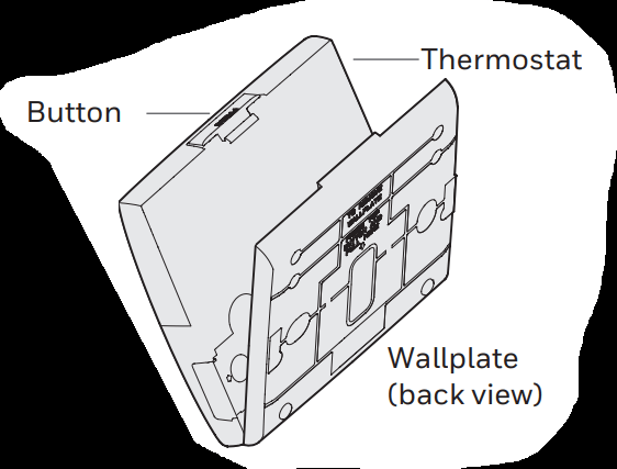
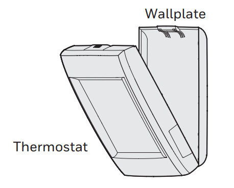
1.1. Separate wallplate from thermostat.
If your thermostat has a button along the top of the wallplate, press button on top and pull to remove the wallplate as shown. Updated models do not have this button. On those models pull evenly along the sides and bottom of the thermostat to separate it from the wallplate.
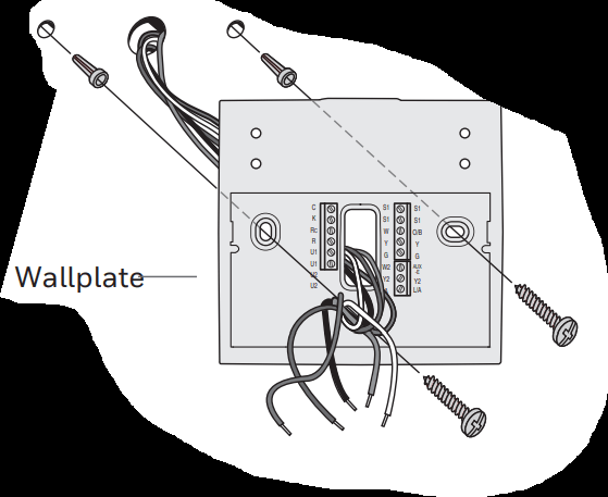
1.2. Mount wallplate as shown.
Mount new wallplate using screws and anchors included with the thermostat. Drill 3/16-in holes for drywall. Drill 7/32-in holes for plaster.
1.3. Connect power.
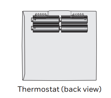
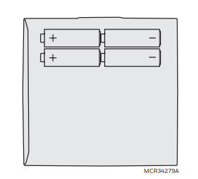
1.3a Insert supplied AA alkaline batteries for primary or backup power.
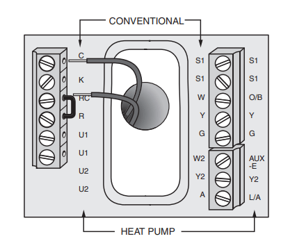
NOTE: When the thermostat is NOT used with the Equipment Interface Module or the TrueZONE Wireless Adapter, a C wire is required for RedLINK.
1.3b For 24VAC primary power, connect common side of transformer to C terminal.
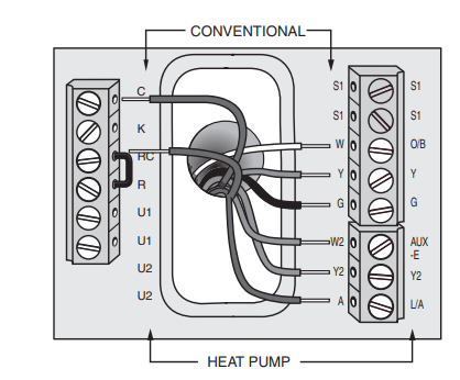
1.4 Wire the thermostat.
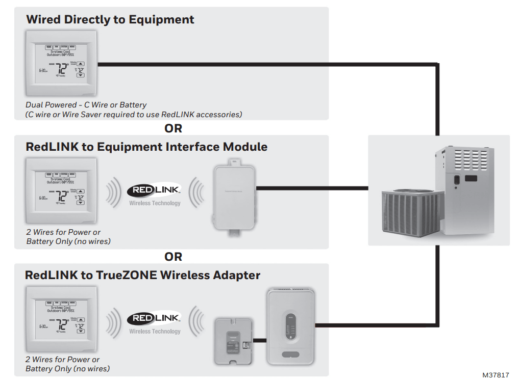
Is the thermostat wired directly to the equipment?
If the thermostat is wired directly to the equipment:
Refer to the table and wiring diagrams on the next page.
Turn on 24VAC NOW. 24VAC (C wire) is required to connect RedLINK accessories.
If the thermostat is used with an Equipment Interface Module or TrueZONE Wireless Adapter, power the thermostat using Rc and C terminals or with batteries.
NOTE: The relay outputs and inputs on the thermostat do not function when used with an Equipment Interface Module or TrueZONE Wireless Adapter.
1.5 With thermostat removed from sub-base, insert the coin cell battery.
NOTE: On some models the coin cell battery compartment slides out from the left side of the thermostat when viewing it from the back (not pictured).
1.6 Mount thermostat on wallplate.
NOTE: If your thermostat has hinges at the bottom of the wallplate as shown, insert the thermostat into the hinges, then push the top toward the wall until it snaps together. Updated models do not have hinges. On those models push evenly along the sides and bottom of the thermostat to connect it to the wallplate.
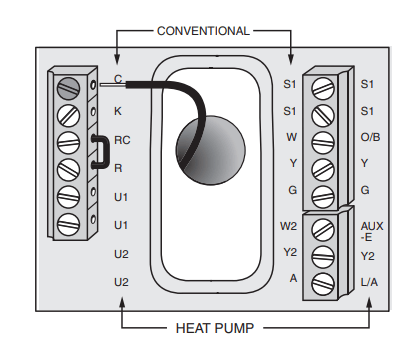
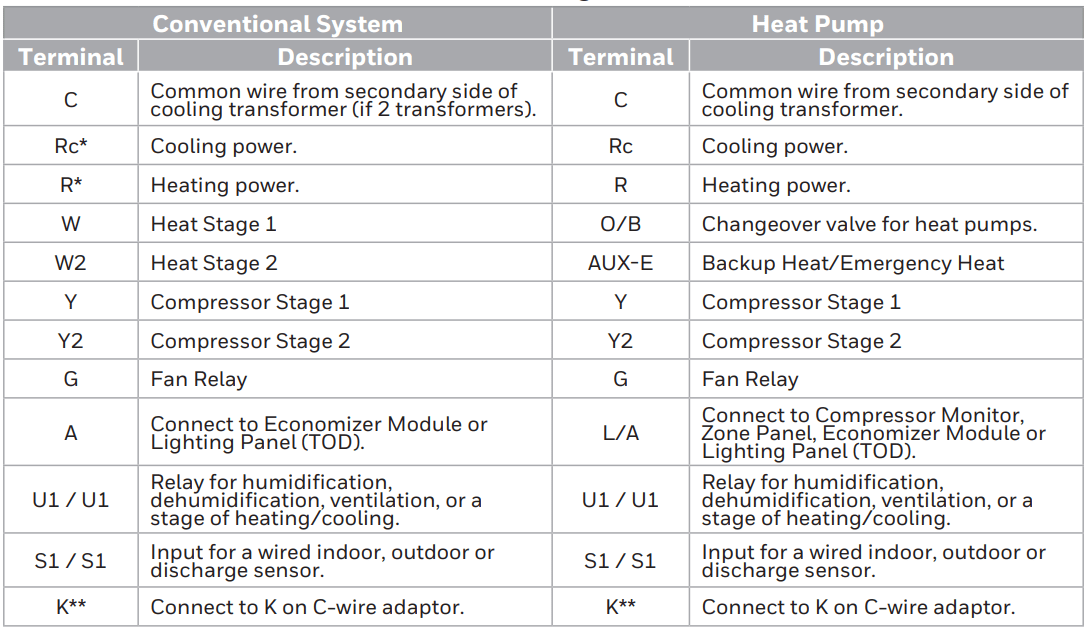
Terminal Designations
* Remove factory installed jumper for two transformer systems.
** The THP9045A1098 C-wire adaptor is used on heat/cool systems when you only have four wires at the thermostat and you would like the thermostat to be powered with a common wire. Use the K terminal in place of the Y and G terminals on conventional or heat pump systems to provide control of the fan and the compressor through a single wire—the unused wire then becomes your common wire. See THP9045 instructions for more information.
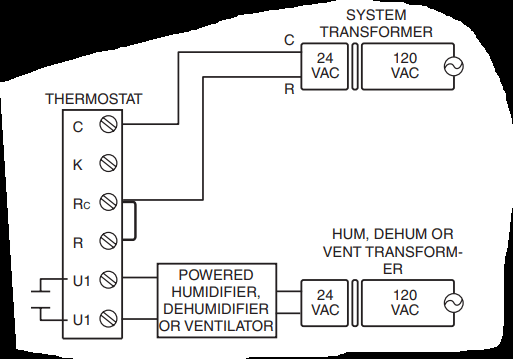
POWERED HUMIDIFIER, DEHUMIDIFIER OR VENTILA-TOR
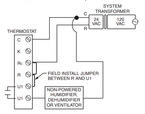
NON-POWERED HUMIDIFIER, DEHUMIDIFIER OR VENTILATOR
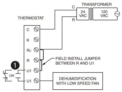
DEHUMIDIFICATION WITH LOW SPEED FAN
Wire the thermostat U1 terminal to the low speed fan for dehumidification control at the equipment as shown. The relay can be set to normally open or normally closed in the installer setup.
Normally open, dry contacts
Normally closed, dry contacts
CONNECTING A HEAT OR COOL STAGE TO U1
U1 terminals are normally open dry contacts when set up for a stage of heating or cooling.
You must install a field jumper if the stage of heating or cooling is powered by system transformer. Do NOT install a field jumper if the stage of heating has its own transformer.
Powering optional RedLINK accessories
2.1 Install batteries in RedLINK accessories.
Portable Comfort Control
Wireless Outdoor Sensor*
Wireless Indoor Sensor*
Wireless Entry/Exit Remote*
Wireless Vent and Filter Boost Remote* * Requires setup. See Installer Setup options in Step 3.4.
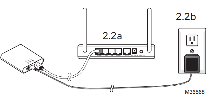
2.2 Connect gateway to internet and connect to power.
2.2a Connect RedLINK Internet Gateway to router or modem with Ethernet cable (RJ45).
2.2b Connect gateway’s power cord to an electrical outlet that is not controlled by a wall switch.
NOTE: If the thermostat is wired directly to the equipment, 24VAC (C wire) is required to connect RedLINK accessories. Turn on 24VAC before performing initial setup in Step 3.
Performing initial setup
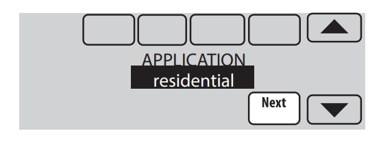
Initial setup options define the type of system you are installing:
Residential or commercial
Non-zoned or zoned
Used with or without an Equipment Interface Module (THM5421)
Used with or without the TrueZONE Wireless Adapter (THM4000)
3.1 Follow prompts on the screen to select the appropriate options.
NOTE: If you are connecting the thermostat to the TrueZONE Wireless Adapter (THM4000), refer to the TrueZONE instructions to link the thermostat and RedLINK accessories. Then go to Step 3.4.
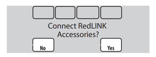
3.2 When you see the prompt Connect RedLINK Accessories? Touch No or Yes.
If you select No, continue to Step 3.4.
If you select Yes, you will be prompted to Press Connect on New Accessories. Continue to Step 3.3.
3.3 Connect each RedLINK accessory.
NOTE: Accessories must be at least 2 feet away from the thermostat during the linking process.
3.3a While the Press Connect message is displayed (listening mode), press and quickly release the CONNECT button on each new RedLINK accessory.
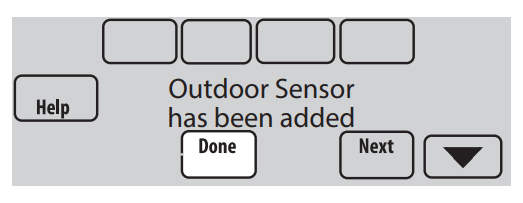
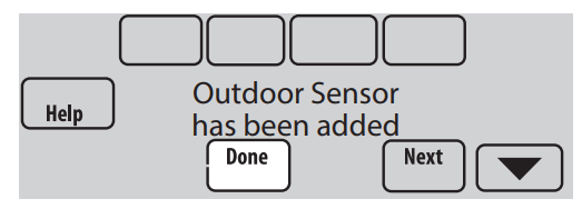
3.3b After a short delay (up to 15 seconds), check thermostat to confirm the connection of each RedLINK accessory. Touch or to review the list.
3.3c Touch Done at the thermostat after all new RedLINK accessories are connected.
NOTE: Thermostat displays a countdown timer while in the listening mode. If it detects no activity for 15 minutes, it exits listening mode.
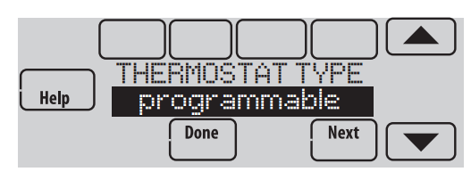
3.4 Finish the initial setup.
Finish the setup by selecting the desired options. Touch Done after you select the last option you want to change.
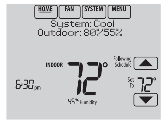
The thermostat now displays its Home screen and the thermostat setup is complete.
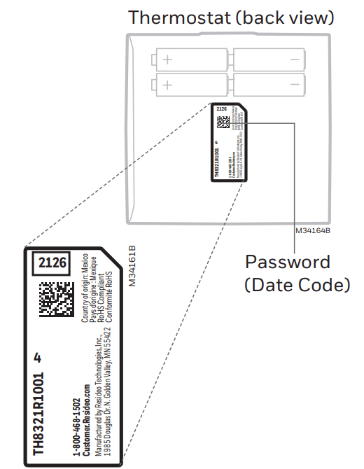
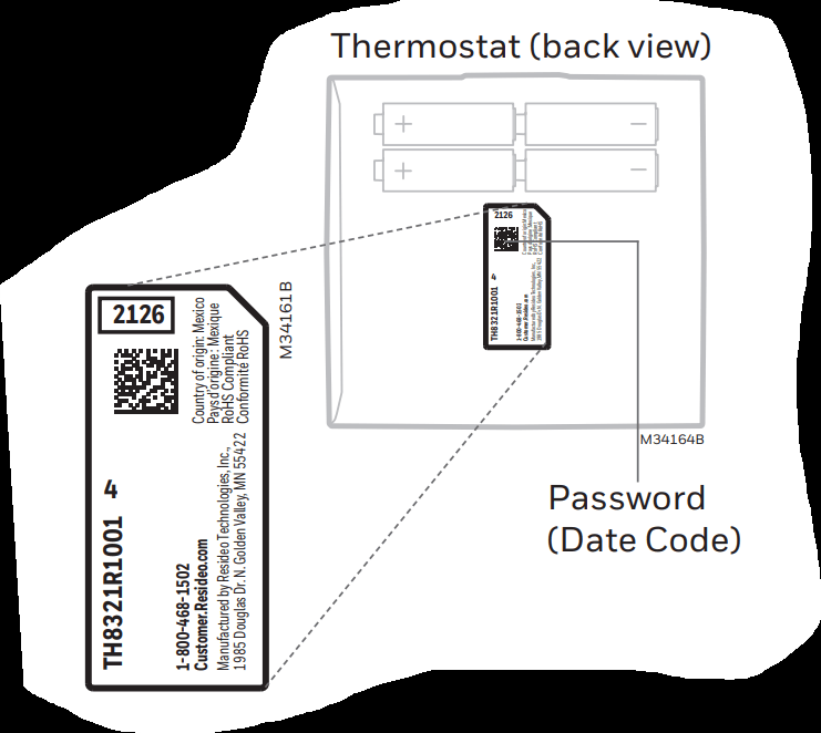
Finding your password (Date Code)
To add or remove RedLINK accessories
To make changes to Installer Setup
To perform an Installer Test
Finding your password
You can find the date code on the back of the thermostat, or
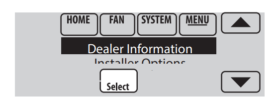
1. Touch Menu.
2. Select Dealer Information.
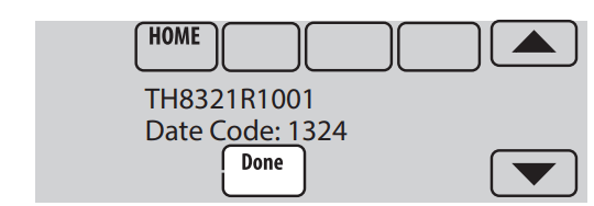
3. Scroll down to see the Date Code.
Linking RedLINK accessories to the thermostat
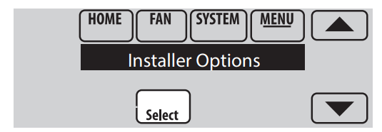
1. Touch Menu.
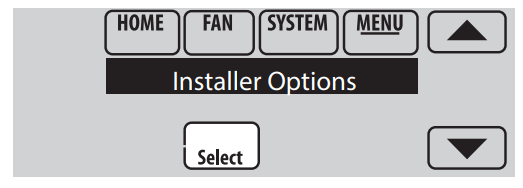
2. Select Installer Options.
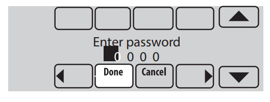
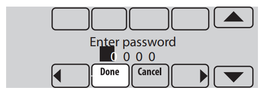
3. Enter password (date code) and touch Done.
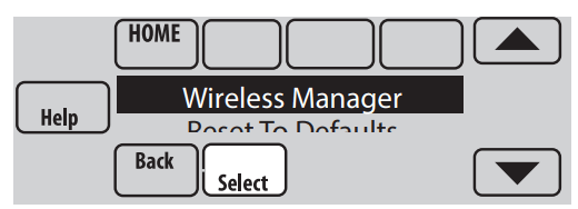
4. Select Wireless Manager.
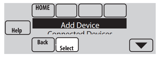
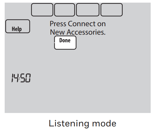
5 Select Add Device. The screen displays “Press Connect on New Accessories.” The thermostat is now in listening mode.
NOTE: Accessories must be at least 2 feet away from the thermostat during the linking process.
5a. Press and quickly release the CONNECT button on each new RedLINK accessory.
5b. After a short delay (up to 15 seconds), check thermostat to confirm the connection of each RedLINK accessory. Touch s or t to review the list.
5c. Touch Done at the thermostat after all new RedLINK accessories are connected.
NOTE: Thermostat displays a countdown timer while in the listening mode. If it detects no activity for 15 minutes, it exits listening mode.
Making changes to Installer Setup and performing an Installer Test
NOTE: Use a microSD card to save set up time. See next page.
1. Touch Menu.
2. Select Installer Options.
3. Enter password (date code) and touch Done.
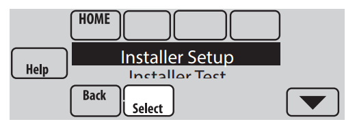
4. Select Installer Setup or Installer Test.
5. Follow prompts on the screen to select the desired setup options or to perform an equipment test.
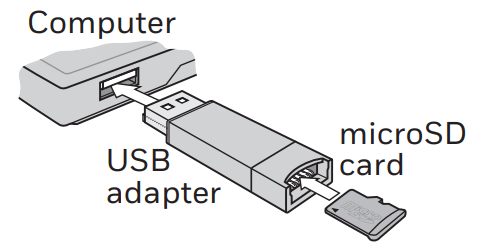
Using a microSD card for setup, data logs and software upgrades
Use a microSD (secure digital) card to save setup time by loading Installer Setup settings, Dealer Information, Holiday Schedules, and Custom Reminders to multiple thermostats. For troubleshooting help, you can save the thermostat Data Logs (Alerts Log and Interaction Log) to a microSD card - then view them on your computer. Also use the microSD card to upgrade the thermostat software.
Loading Dealer Information and New Thermostat Software:
1. Visit http://thermostatsetup.honeywell.com to enter your dealer information or load new thermostat software.
2. Connect a microSD USB Adapter to your computer to download the file(s).
3. After the file(s) are downloaded, remove the microSD card from the adapter and insert into thermostat.
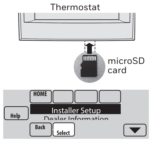
To use the microSD card in the thermostat:
1. Slide card into the bottom of thermostat.
2. Select the item to load or save.
3. Follow the prompts on the screen.
To add information from the card to the thermostat, select Load from SD Card.
To put thermostat information on the card, select Save to SD Card.
4. When you are finished, touch Done, then Home, and remove the microSD card.
To replace a thermostat
When you replace a thermostat, you must reset the RedLINK accessories before connecting them to the new thermostat. Follow the instructions below:
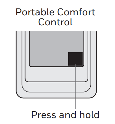
At the Portable Comfort Control:
Press and hold the blank space (or arrow) in the lower right hand corner of the screen until the display changes (hold for about 4 seconds). Press REMOVE, then YES to disconnect from the old thermostats. To reconnect the thermostat, go to Step 3.2.
At the Indoor Sensor, RedLINK Internet Gateway, Entry/Exit Remote, Vent-Filter Boost Remote or TrueSTEAM Wireless Adapter:
Press and hold the CONNECT button on the accessory until the status light glows amber (hold for about 10 seconds). To reconnect the thermostat, go to Step 3.2.
At the Equipment Interface Module (EIM): Press and hold the CONNECT button on the EIM until the CONNECTED LED glows amber (hold for about 10 seconds). Follow the prompts on the screen to connect the new thermostat to the EIM.
#1 Do I need to have redlink or other adapter to connect to wi-fi? I'm not operating any remote tstats or sensors
Yes you would with this thermostat. A better option if you wanted a thermostat to connect to Wifi without needing any extra adapters would be TH8321WF1001.
#2 Does this unit require a "C" wire or Common wire to connect to a Redlink Gateway?
You can run without the 'C' wire , but if you connect with a Gateway - you will most likely need it , or be prepared to be standing by ready to change batteries constantly due to the 24/7 communication between the stat and the gateway.
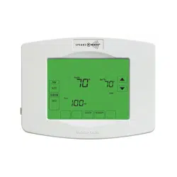
ADAPTIVE INTELLIGENT RECOVERY Over time, the VisionPRO® thermostat "learns" how long it takes your system to reach your programmed temperature setting. The thermostat turns on the heating/cooling system early and assures that the programmed temperature setting is reached at the programmed time regardless of weather conditions. For example, if the Wake program period is set to 6:00 am with a heat setting of 70 degrees, the heat will turn on before 6:00 am, so the temperature is 70 degrees at 6:00 am. The thermostat displays "In Recovery" when it turns the system on early. Adaptive Intelligent Recovery® calculates the recovery ramp based on how far the room temperature is away from the temperature setting, previous equipment performance and weather history, allowing the thermostat to start recovery at the optimal time so it can reach the programmed temperature setting at the programmed time
#4 My old thermostat has s1 and s2 wires, are these same as s1 and s1 on this thermostat?
I'm not exactly sure. I'm sure you can find a mapping chart online. From my experience the wires should be the same for all thermostats.
-645717.jpg)
 Normally open, dry contacts
  Normally closed, dry contacts
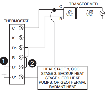
 or
or  to review the list.
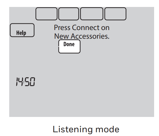
 Using a microSD card for setup, data logs and software upgrades