Owner 's Manual for Thermostat
Your new thermostat has been designed to give you many years of reliable service and easy-to-use, push-button climate control.
Features
• Backlit display is easy to read
• Displays ambient (measured) temperature at all times
• One-touch access to setpoint temperature
• Built-in compressor protection
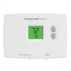
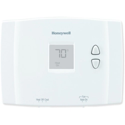
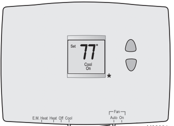
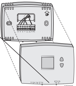
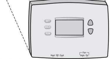
Quick reference to controls
* Model TH1110E1000 has a larger display than shown in image.
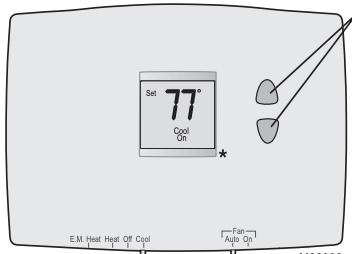
Up/Down buttons
Press to adjust temperature.
Fan Switch (see page 6)
- On: Fan runs continuously.
- Auto: Fan runs only when heating or cooling system is on.
System switch (see page 5)
• Cool: Cooling system control.
• Off: All systems off.
• Heat: Heating system control.
• Em Heat: Emergency & Auxiliary Heat control. Compressor is locked out. (Select models only.)
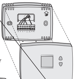
Quick reference to display screen
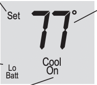
Setpoint indicator
Appears when the setpoint temperature is displayed
Note: On model TH1110E1000, “Set” appears to the right of the temperature.
Low battery warning (see page 9)
Note: Model TH1110E1000 does not show Lo Batt. It shows a battery with only 1 bar of charge in the lower right corner of the display.
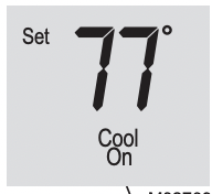
System status
- Cool on: Cooling system is on.
- Heat on: Heating system is on.
- Aux On: Auxiliary heat is on. (Only for heat pumps with this capability [select models only].) When “Heat On” or “Cool On” is flashing, compressor protection is engaged (see page 8).
Temperature
The ambient (measured) temperature is normally displayed. To view the setpoint temperature, press the Up or Down button once. The setpoint temperature will appear for five seconds.
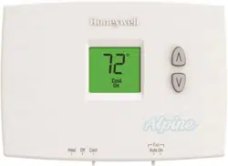
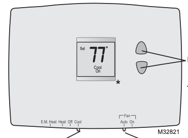
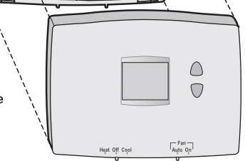
Select the system setting
Set SYSTEM switch to control the heating or cooling system.
* Model TH1110E1000 has a larger display than shown in image.
The SYSTEM switch can be set to control your heating or cooling system, depending on the season.
- Cool: Cooling system control.
- Off: All systems are off.
- Heat: Heating system control.
- Em Heat: Emergency & Auxiliary Heat control. Compressor is locked out. (Select models only.)
 CAUTION: EQUIPMENT DAMAGE HAZARD. To prevent possible compressor damage, do not operate cooling system when outdoor temperature is below 50°F (10°C).
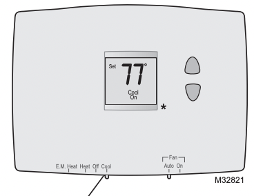
Select the fan setting
Set FAN switch to choose whether the fan runs continuously or only as needed.
* TH1110E1000 model has a larger display than shown in image.
Set the FAN switch to Auto or On.
In “Auto” mode (the most commonly used setting), the fan runs only when the heating or cooling system is on.
If set to “On,” the fan runs continuously
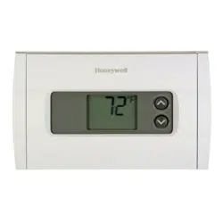
Adjust the temperature
Press  or
or  to adjust the temperature.
Note: Make sure the thermostat is set to the system you want to control (heat or cool).
Built-in compressor protection
Message flashes until safe restart time has elapsed.
This feature helps prevent damage to the compressor in your air conditioning or heat pump system.
Damage can occur if the compressor is restarted too soon after shutdown. This feature forces the compressor to wait 5 minutes before restarting.
During the wait time, the display will flash the message Cool On. When the safe wait time has elapsed, the message stops flashing and the compressor turns on.
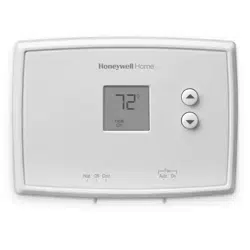
Battery replacement
Turn thermostat over, insert fresh AAA alkaline batteries, then reinstall thermostat.
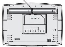
Pull at bottom to remove thermostat from wallplate.
Install two fresh AAA batteries when either Lo Batt or battery icon appears on the screen. The low battery indicator appears for 60 days before the batteries are depleted.
Replace batteries once a year, or when you will be away for more than a month.
The settings are stored in nonvolatile (permanent) memory and are thus preserved when the thermostat is without batteries.
Set the System switch to Off before removing the batteries. Otherwise, the heating/cooling system could remain activated even when batteries are removed.
Customer assistance
Turn thermostat over to find model number and date code.
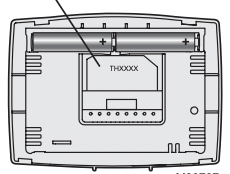
Pull at bottom to remove thermostat from wallplate.
For assistance with this product, please visit Honeywellhome
In case of difficulty
If you have difficulty with your thermostat, please try the following suggestions. Most problems can be corrected quickly and easily.
Display is blank
- Make sure fresh AAA alkaline batteries are correctly installed (see page 9).
Heating or cooling system does not respond
- Set system switch to Heat (see page 5). Make sure the temperature is set higher than the Inside temperature.
- Set system switch to Cool (see page 5). Make sure the temperature is set lower than the Inside temperature.
- Wait 5 minutes for the system to respond.
- Check circuit breaker and reset if necessary.
- Make sure power switch at heating & cooling system is on.
- Make sure furnace door is closed securely
“Heat On” or “Cool On” is flashing
- Compressor protection feature is engaged. Wait 5 minutes for the system to restart safely, without damage to the compressor (see page 8).
“Heat On” is not displayed
- Set the System switch to Heat, and set the temperature level above the current room temperature (see page 5).
“Cool On” is not displayed
- Set the System switch to Cool, and set the temperature level below the current room temperature (see page 5).
Installation Guide
System Types
• Gas, oil, or electric heat
• Warm air, hot water, steam, gravity
• Heat only
• 750 mV heating systems
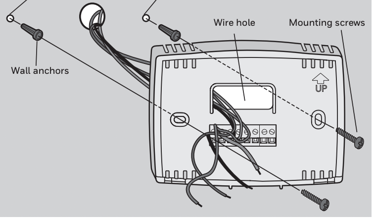
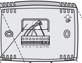
Wallplate installation
Pull at bottom to remove thermostat from wallplate.
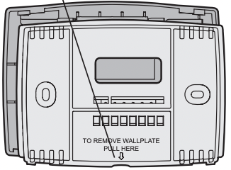
Remove the wallplate from the thermostat as shown at left, then follow directions below for mounting.
- Pull wires through wire hole.
- Position wallplate on wall, level and mark hole positions with pencil.
- Drill holes at marked positions as shown below, then tap in supplied wall anchors.
- Place wallplate over anchors, insert and tighten mounting screws.
Drill 3/16" holes for drywall. Drill 7/32" holes for plaster
 CAUTION: ELECTRICAL HAZARD Can cause electrical shock or equipment damage. Disconnect power before beginning installation.
MERCURY NOTICE If this product is replacing a control that contains mercury in a sealed tube, do not place the old control in the trash. Contact the Thermostat Recycling Corporation at thermostat-recycle or 800-238-8192 for information on how and where to properly and safely dispose of your old thermostat.
Power options
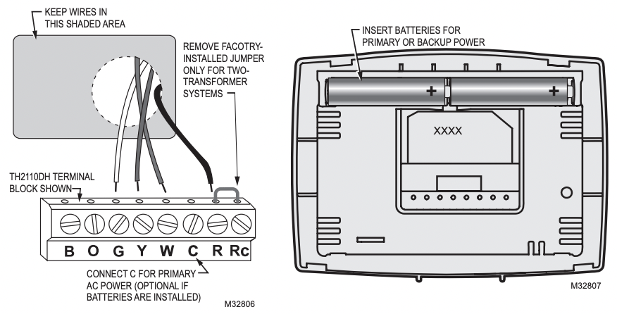
W Heat relay
C 24 Vac common
R 24 Vac power
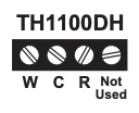
Wiring
Wiring guide — conventional and heat pump systems

W Heat relay
C 24Vac common [3]
R Power [1]
NOTES
Wire specifications: Use 18- to 22-gauge thermostat wire. Shielded cable is not required.
[1] Power supply. Provide disconnect means and overload protection as required.
[2] Remove jumper for 2-transformer systems.
[3] Optional 24 Vac common connection
Thermostat mounting
Align the 2 tabs at the top of the wallplate with corresponding slots on the back of the thermostat, then push gently until the thermostat snaps in place.
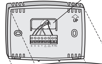
Push excess wire back into the wall opening.
Plug wall opening with non-flammable insulation
Settings are the same on TH1110E1 & TH1110DH models. TH1110E1 has a larger display
Installer setup
| Setup function |
Settings & options (factory default in bold) |
|
5 Heating cycle rate
(CPH: cycles/hour)
TH2110DH, TH1110E1, TH1110DH and TH1100DH
|
5 For gas or oil furnaces of less than 90% efficiency
1 For steam or gravity systems
3 For hot water systems & furnaces of over 90% efficiency
6 For electric furnaces
[Other cycle rate options: 2 or 4 CPH]
|
| 9 Compressor cycle rate (CPH) |
3 Recommended for most compressors
[Other cycle rate options: 1, 2, 4, 5, or 6 CPH]
|
| 14 Temperature display |
0 Fahrenheit
1 Celsius
|
| 15 Compressor protection |
1 Five-minute compressor off time (See page 8)
0 No compressor off time
|
| 25 Lower temperature range (TH1100DH only) |
0 Standard range 40°F to 90°F (4.5°C to 32°C)
1 Lower range (for garage mode) 35°F to 90°F (1.5°C to 32°C)
|
CAUTION: EQUIPMENT DAMAGE HAZARD Compressor protection is bypassed during testing. To prevent equipment damage, avoid cycling the compressor quickly
Special functions
Early Start (Setup Function 13): Early start allows the heating or cooling to turn on before the program start time, so the temperature is reached at the time you set.
Compressor Protection (Setup Function 15): Forces the compressor to wait a few minutes before restarting, to prevent damage. During the wait time, the message Cool On (or Heat On for TH2210DH & TH1210DH) will flash on the display