USER MANUAL
UWP Mounting System installation
|
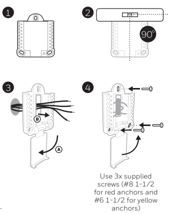
1. Open package to find the UWP. See Figure 1.
2. Position the UWP on the wall. Level and mark hole positions. See Figure 2.
Drill holes at marked positions, and then lightly tap supplied wall anchors into wall using a hammer.
- If your box contains red anchors, drill holes.
- If your box contains yellow anchors, drill 3/16” holes.
3. Pull the door open and insert wires through wiring hole of the UWP. See Figure 3.
4. Place the UWP over the wall anchors. Insert and tighten mounting screws supplied with the UWP. Do not overtighten. Tighten until the UWP no longer moves. Close the door. See Figure 4.
|
|
 |
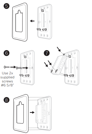
Optional Cover Plate installation
|
Use the Optional Cover Plate when:
- Mounting the thermostat to an electrical junction box
- Or when you need to cover paint gap from the old thermostat.
5. Separate the Junction Box Adapter from the Cover Plate. See Figure 5.
6. Mount the Junction Box Adapter to the wall or an electrical box using any of the eight screw holes. Insert and tighten mounting screws supplied with Cover Plate Kit. Do not overtighten. Make sure the Adapter Plate is level. See Figure 6.
7. Attach the UWP by hanging it on the top hook of the Junction Box Adapter and then snapping the bottom of the UWP in place. See Figure 7.
8. Snap the Cover Plate onto the Junction Box Adapter. See Figure 8.
|
|
 |
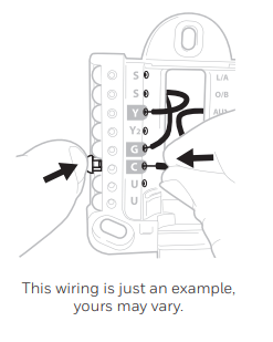
Wiring UWP
Push down on the tabs to put the wires into the inner holes of their corresponding terminals on the UWP (one wire per terminal) until they are firmly in place. Gently tug on the wires to verify they are secure. If you need to release the wires again, push down the terminal tabs on the sides of the UWP.
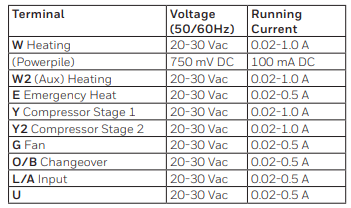
Terminal designations
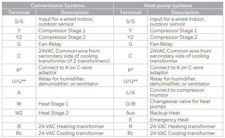
* The THP9045A1098 C-wire adaptor is used on heat/cool systems when you only have four wires at the thermostat and you need a fifth wire for a common wire. Use the K terminal in place of the Y and G terminals on conventional or heat pump systems to provide control of the fan and the compressor through a single wire—the unused wire then becomes your common wire. See THP9045 instructions for more information.
** See note on Wiring U terminals on the following page.
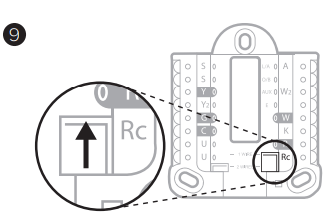
Setting Slider Tabs
Set R Slider Tab, see Figure 9.
- Use built-in jumper (R Slider Tab) to differentiate between one or two transformer systems.
- If there is only one R wire, and it is connected to the R, Rc, or RH terminal on the old thermostat, set the slider to the up position (1 wire).
- If there is one wire connected to the R terminal and one wire connected to the Rc terminal, set the slider to the down position (2 wires).
|
|
 |
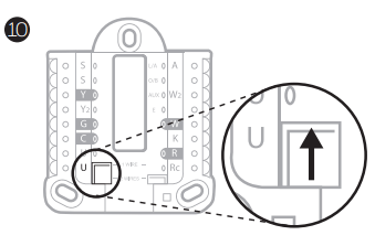
Set U Slider Tab, see Figure 10.
- Use built-in jumper (U Slider Tab) for IAQ device.
- When the U Slider Tab is in the down position (2 wires) the U contacts are a dry set of contacts.
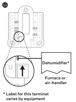
- If your IAQ device is powered by the cooling transformer, move the U Slider Tab to the up position (1 wire). When this is done, the lower U terminal is internally jumped to the Rc terminal. In this application, you would hook up one wire from your IAQ device to the upper U terminal and the other to the common side of the cooling transformer. The 1 wire setting is most commonly used when using a fresh air damper for ventilation or using low speed fan for dehumidification.
- See wiring examples on the next page.
|
|
 |
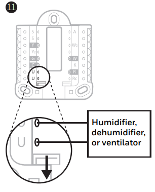
Whole house humidifier, dehumidifier, or ventilator
Using U Slider Tab
| Wired to humidifier, dehumidifier or ventilator with built-in transformer. |
|
 |
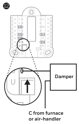
| Wired to fresh air damper powered by furnace transformer. |
|
 |
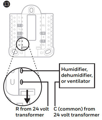
| Wired to humidifier, ventilator, or damper powered by external transformer |
|
 |
| Wired to low speed fan terminal on HVAC for dehumidification |
|
 |
Wiring
NOTES:
- Use 18- to 22- gauge thermostat wire. Shielded cable is not required.
- Set the R Slider Tab on the UWP to the up position (1 wire) for 1 transformer systems or the down position (2 wires) for 2 transformer systems. See "Setting Slider Tabs" on page 4.
- Set the U Slider Tab as shown in the diagrams on page 4.
Conventional systems
|
1H/1C System (1 transformer)
R Power
Rc [R+Rc joined by Slider Tab]
Y Compressor contactor
C* 24VAC common
W Heat relay
G Fan relay
|
|
Hot Water Relay Panel
R Power
Rc [R+Rc joined by Slider Tab]
W Heat Relay
C* 24VAC common
|
|
1H/1C System (2 transformers)
R Power (heating transformer)
Rc Power (cooling transformer)
Y Compressor contactor
C* 24 VAC common from cooling transformer
W Heat relay
G Fan relay
|
|
Heat-only System with Fan
R Power
Rc [R+Rc joined by Slider Tab]
C* 24VAC common
W Heat relay
G Fan relay
|
|
2H/2C System (1 transformer)
R Power
Rc [R+Rc joined by Slider Tab]
Y Compressor contactor (stage 1)
C* 24VAC common
W Heat relay (stage 1)
G Fan relay
W2 Heat relay (stage 2)
Y2 Compressor contactor (stage 2)
|
|
Cool-only System with Fan
R Power
Rc [R+Rc joined by Slider Tab]
Y Compressor contactor
C* 24VAC common
G Fan relay
|
Heat pumps systems
|
1H/1C Heat Pump System
R Power
Rc [R+Rc joined by Slider Tab]
Y Compressor contactor
C* 24VAC common
O/B Changeover valve
G Fan relay
|
|
2H/2C Heat Pump System
R Power
Rc [R+Rc joined by Slider Tab]
Y Compressor contactor (stage 1)
C* 24VAC common
O/B Changeover valve
G Fan relay
Y2 Compressor contactor (stage 2)
L Heat pump fault input
|
|
2H/1C Heat Pump System
R Power
Rc [R+Rc joined by Slider Tab]
Y Compressor contactor
C* 24VAC common
O/B Changeover valve
G Fan relay
Aux Auxiliary heat**
E Emergency heat relay**
L Heat pump fault input
|
|
3H/2C Heat Pump System
R Power
Rc [R+Rc joined by Slider Tab]
Y Compressor contactor (stage 1)
C* 24VAC common
O/B Changeover valve
G Fan relay
Aux Auxiliary heat**
E Emergency heat relay**
Y2 Compressor contactor (stage 2)
L Heat pump fault input
|
NOTE: Do NOT use W for heat pump applications. Auxiliary heat must wire to AUX or E.
Mounting thermostat
- Push excess wire back into the wall opening.
- Close the UWP door. It should remain closed without bulging.
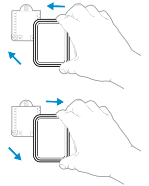
- Align the UWP with the thermostat, and push gently until the thermostat snaps in place.
Note: If you used the Optional Cover Plate shown on page 2, remove the gray trim ring from the thermostat before step 3. Then align the thermostat with cover plate and push gently until the thermostat snaps into place.
Note: If needed, gently pull to remove the thermostat from the UWP
|
|
 |
Installer setup
|
The display will walk you through equipment setup, connecting to wireless sensors and connecting to Wi-Fi.
The final step in the setup is a place you can enter your company name and contact information as well as your Contractor PRO™ number.
That contact information will be displayed with alert or reminder messages to keep you connected to your customer
|
|
 |
Sensor installation
|
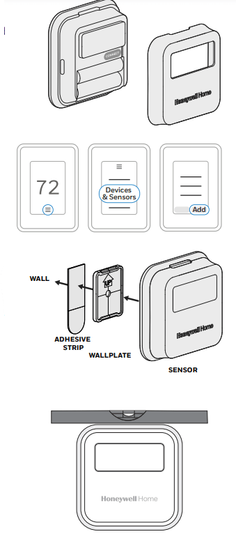
Remove white cover from grey base and Insert (2) AAA Alkaline batteries in the sensor.
Open the menu.
Tap "Devices & Sensors."
Tap "Add."
Follow the on-screen instructions.
Snap the sensor onto the wall-plate.
Adhere the included command strip to the wall-plate. Then adhere the sensor to the wall. Level sensor for appearance. (See the sensor instructions for proper placement.)
|
|
 |
How to use your thermostat
The screen will wake up by pressing the center area of the displayed temperature.

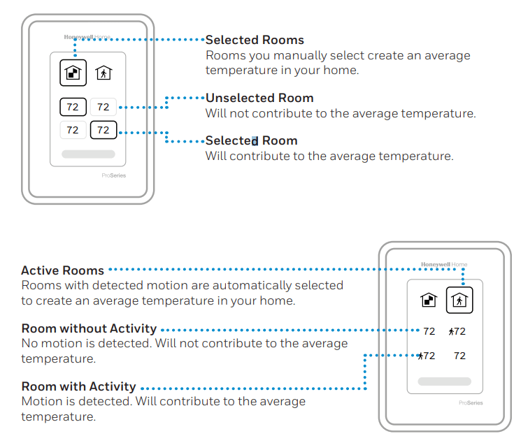
How to use Priority
Priority creates an average temperature in your home based on specific rooms. This allows you to prioritize comfort where you want it.
How to find more options
- Touch the menu button.
- Scroll up and down for more options.
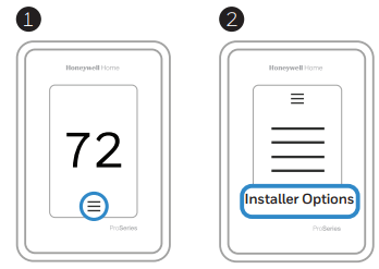
Menu options include
Installer Setup
- System type
- IAQ control (hum, dehum, vent) reminders
Installer Test
- Turn on heat, cool, or IAQ equipment
Devices & Sensors
- View, add, or remove RedLINK indoor sensors
- Identity wireless sensors
- Add wireless sensors Device Information
Thermostat Information
- MAC ID number
- IP address
- Date code
- Model number
- Build date
- Stat app
- Firmware version
- Stat app boot #
- Hardware
Dealer Information
Finding date code (pass code) for installer setup.
Open the Menu icon, and choose Thermostat Information. Write down date code.
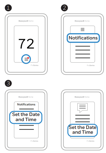
Alerts and notifications
- The red dot above the Menu icon indicates an active alert or notification. Touch the Menu icon to view active Alerts & Notifications.
- Touch Notifications to open this menu.
- Touch the alert message to see more information about the alert.
|
|
 |
Troubleshooting
| Screen is blank |
- Check circuit breaker and reset if necessary.
- Make sure power switch at heating and cooling system is on.
- Make sure furnace door is closed securely.
|
| Screen is difficult to read |
- Check setting in MENU/ Preferences / Inactive backlight brightness or Inactive sleep backlight brightness
|
| Heating or cooling system does not respond |
- Touch MENU to go to system mode. Set to heat. Make sure the heat setpoint is above the room temperature.
- Touch MENU to go to system mode. Set to cool. Make sure the cool setpoint is below the room temperature.
- Check circuit breaker and reset if necessary.
- Make sure power switch at heating & cooling system is on.
- Make sure furnace door is closed securely.
|
| Temperature settings do not change |
Make sure heating and cooling temperatures are set to acceptable ranges:
- Heat: 40 °F to 90 °F (4.5 °C to 32.0 °C)
- Cool: 50 °F to 99 °F (10.0 °C to 37.0 °C)
|
| Cool On” or “Heat On” is flashing |
- Compressor protection feature is engaged. Wait 5 minutes for the system to restart safely, without damage to the compressor.
|
| Aux heat runs in cooling |
- For heat pump systems, verify there is not a wire attached to W on UWP systems. See “Heat pumps systems" on page 7.
|
| Cool runs with a call for heat |
- For heat pump systems, verify there is not a wire attached to W on UWP systems. See “Heat pumps systems" on page 7.
|
| Heat runs with cooling |
- Verify there is not a wire attached to W for heat pump systems. See "Wiring" on pages 6-7.
|
| Sensor will not connect |
- Press and hold Connect on the wireless sensor for seconds. The LED will turn Amber. Return to the thermostat menu and press Menu > Devices andSensors. Follow the on-screen instructions to add the sensor.
|
Specifications
Temperature Ranges
Heat: 40 °F to 90 °F (4.5 °C to 32.0 °C)
Cool: 50 °F to 99 °F (10.0 °C to 37.0 °C)
Operating Ambient Temperature
32°F to 120 °F (0 °C to 48.9 °C)
Shipping Temperature
-20°F to 120 °F (-28.9 °C to 48.9 °C)
Operating Relative Humidity
5%to 90% (non-condensing)
Electrical Ratings
Power Consumption
3VA
Physical Dimensions in inches (mm) (H x W x D)
T10 PRO Wi-Fi Thermostat: x 3.7" x 0.93" (125.4 x 94.1 x 23.68)
UWP Mounting System (included): x 2-13/64" x 2-43/64" (58 x 56 x 10)
Standard Installation Adapter (included): x 3-57/64" x 21/32" (99 x 99 x 17)
Cover Plate – Medium (included): x 5-1/2" x 11/16" (131.4 x 139.7 x 17.5)
Cover Plate – Large (THP2400A1068): x 6-7/64" x 9/32" (155 x 155 x 7)