
Installation Instructions
CAUTION: Failure to read and follow all installation and operating instructions could lead to personal injury and/
or damage to property.
CAUTION: All electrical installations must comply with local building and safety codes and must be performed by
qualied personnel only.
System Overview
• Thiscontrolsystemisintendedtobeusedwithanevaporativecoolerwitha2-speedblowerandawaterpump.Itwillalsooperatea
waterpurgepumporvalve,ifequipped.
• Thecontrolisdesignedforfanmotorsupto1HP(120V)or2HP(240V),withwaterpumpandpurgepumpupto2A(120V)or1A
(240V)
• Thefanmotormaybe120Vor240Vrated.
• Thewaterpumpandpurgepumpmotors/valvessharethesameelectricalsupply,ratedfor120Vor240V.
Included in Kit
• WallControlThermostat
• 2-SpeedEvaporativeCoolerControl
• WireNutforcommonEarthconnection.
• Spare3.15Ampfuseforcontrol.
• JumperwireforLinktoN-Link(TobeusedonlywhenbothFanandPumpvoltagesarethesame).
Additional Requirements
Dependingonapplicationandinstallation,thefollowingadditionalitemsmayberequired:
• ScrewsorboltsformountingtheApplianceControlBoxandWallControl
• WiringforconnectionbetweenpowersupplyandApplianceControlBox;WallControlandApplianceControlBox;andbetween
ApplianceControlBoxandthecoolerconnectionbox.
• Conduitandwatertightconnectorstoprotectallwiring.
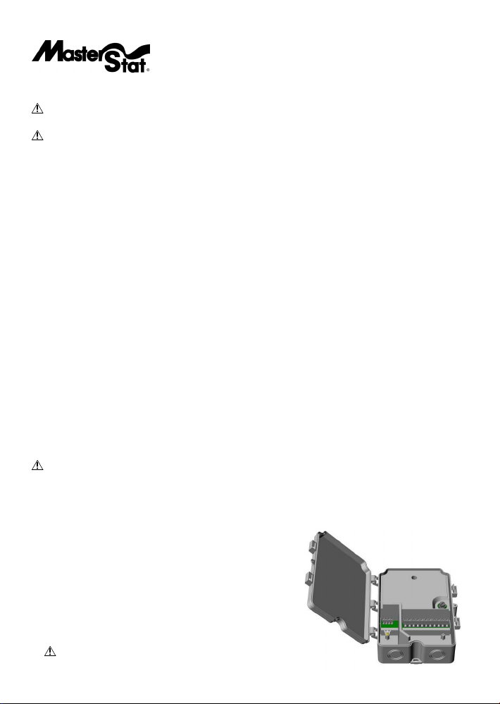
Installation of the Appliance Control Box
CAUTION: To prevent electrical shock and/or damage to the equipment, disconnect electrical power to the system at
the main fuse or circuit breaker before starting the installation, and leave disconnected until the installation is complete.
1) AfterdeterminingasuitableplacetoinstalltheApplianceControlBox,markthelocationofthethreemountingpoints(withthe
‘TOP’indicationuppermost)anddrillpilotholesforthemountingscrews.
2) Determinewhichknockoutlocationswillbeusedforthesystemwiring.
3) Usingasuitabletool,cutouttherequiredknockouts.Makesureyoucutoutthe
correctsizeholeforyourtting.
4) Mounttheboxusingsuitablescrews.
5) Installconduitandconnections,ensuringawatertightseal,especiallyaroundthe
locationswheretheknockoutswereremoved.
6) Runwiring,inaccordancewithlocalandnationalelectricalcodes,tosuitthe
installation.
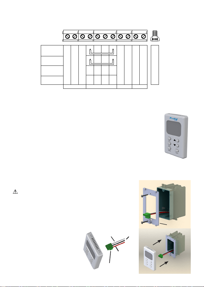
7) Connectthewiresinaccordancewiththewiringdiagramonnextpage(wiring
diagramalsolocatedontheinsidelidofApplianceControlbox).
WARNING: Use the jumper wire between Link and NLink only
when fan and pump voltages are the same.
Wall Control Thermostat and 2-Speed Evaporative Cooler
Control System • Model 110423-2
Installation of the Wall Control - cavity wall without outlet box
1) DetermineasuitableplacetoinstalltheWallControl(awayfromsourcesofheat,sunlight,orventilation,and
between4and6feetfromtheoor).Donotinstallnearcooleropening.
2) Usingthemountingplateasaguide,markthelocationofthetwomountingpointsandtheterminalopening
fortheconnectionterminal.
3) Makeaholeinthewalljustlargeenoughtoaccommodatetheconnectionterminalandassociatedwiring.
4) Routeaninsulatedthree-conductorthermostatcable(orsimilarlowvoltagecable)fromtheApplianceControl
Boxthroughthehole,leavingaboutsixinchesprotruding.
5) Routethewiringthroughtheopeninginthewallcontrolmountingplate.Usingwallanchors,screwthe
mountingplatetothewall.
6) Connectthewirestotheterminalsasperthewiringconnectiondiagrambelow.Thesesamewirecolorsmatch
thoseindicatedonthecontrolbox.
7) Plugtheconnectionterminalintothebackofthewallcontrol.Placethetabsonthemountingplateintotheholesinthetopofthe
thermostatandrotatetheWallControluntilitsnapsontothemountingplate.Youmayusetheprovidedscrewtosecureitinplace.
FLO
FHI
Fcom
Link
L1
N
NLink
Pp
Pcom
Pe
Pecom
Fan/Pump 120V
Fan/Pump 240V
Fan 240V
Pump 120V
Fan 120V
Pump 240V
Fan Low
Fan
Power Supply
Pump Purge
Fan High
Fan Common
Pump Power
Pump Common
Purge Power
Purge Common
Not
Used
Not
Used
N
N NL2
L1
L2
L1 L1 L1
L2
Ground Connections*
*Note: Use the provided wire nut to connect all ground connections for power
supply, fan, pump, purge pump and cooler cabinet.
Warning: Use jumper between Link and NLink only when Fan and Pump
voltages are the same.
Wiring Connections - Use Copper Conductors
Wiring Connections in Appliance Control Box
ConnectionTerminal
Red
Black
White
MountingPlate
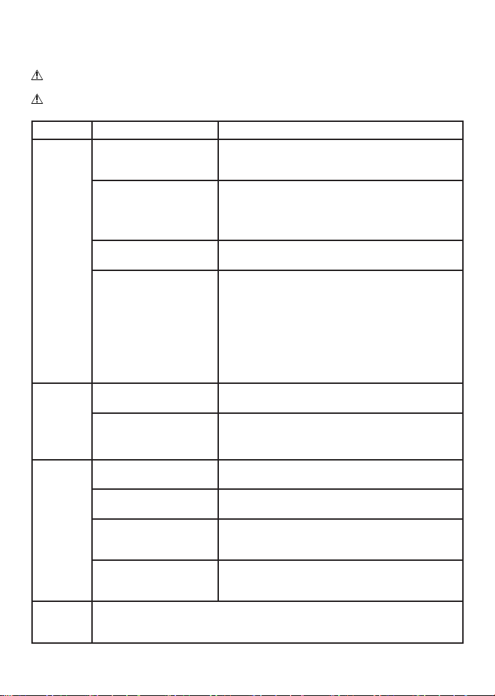
Installation of the Wall Control - using an existing wall-mounted outlet box
CAUTION: Only use a single outlet box and do not share wiring with any other
equipment.
1) Routeaninsulatedthree-conductorthermostatcable(orsimilarlowvoltagecable)fromthe
ApplianceControlBoxtotheoutletbox,leavingaboutsixinchesprotruding.
2) Routethewiringthroughtheopeninginthewallcontrolmountingplate.Screwthemount-
ingplatetotheoutletbox.
3) Connectthewirestotheterminalsasperthewiringconnectiondiagrambelow.These
samewirecolorsmatchthoseindicatedonthe
controlbox.
4) Plugtheconnectionterminalintotheback
ofthewallcontrol.Placethetabsonthe
mountingplateintotheholesinthetopofthe
thermostatandrotatetheWallControluntilit
snapsontothemountingplate.Youmayuse
theprovidedscrewtosecureitinplace.

Operating Instructions
Automatic Operation
The fan and water pump are controlled automatically to achieve the desired comfort level.
Automaticoperationisactivatedbypressingthe‘Mode’buttonuntil‘Auto’isdisplayedontheLCD.The‘Mode’buttonchangesthe
controlbetweenOff,AutoandManual.
TheSettemperature(thetargettemperatureforthecontrol)maybealteredbyrepeatedlypressingorholdingthe‘Up’and‘Down’but-
tons.TheLCDwilldisplay‘Set’ratherthen‘Room’temperatureforashorttimeafterpressingthe‘Up’or‘Down’button.
Onstarting,ifthepadsinthecooleraretoodry,thefanmaybedelayedfromstartinguntilthepadshaveabsorbedsomewater.Thisis
calledPre-Wetandlastsfor2minutes,indicatedby‘Pre-Wet”ashingontheLCD.ThePre-Wetcanbebypassedbyenteringmanual
modebyeitherpressingthe‘Fan’,‘Pump’or‘Mode’buttonandthenpressingthe‘Mode’buttonuntil‘Auto’isdisplayed.
Duringautomaticoperation,thecontrolperformsawaterpurgecycleevery8or12hoursofpumpoperation.Thisintervalcanbe
toggledbetween8or12hoursbysimultaneouslyholdingthe‘Pump’and‘Fan’buttonsfor5seconds.Theselectedintervalisdisplayed
forashorttime.PresstheUporDownarrowbuttonstochangebetween8or12hours.Thisactionalsostartsamanualpurgecycle.A
purgepumporpurgevalve,whichisnotsuppliedwiththethermostatcontrolorevaporativecooler,isrequiredforthisoperation.
Manual Operation
The fan speed and pump are set by the user.
Toactivatethemanualmodefromthe‘Off’state,pressthe‘Mode’buttonuntil‘Manualisdisplayed.Ifthecontrolisinthe‘Auto’
mode,youcanchangetomanualmodebypressingeitherthe‘Mode’,‘Fan’or‘Pump’buttons.Eachpressofthe‘Fan’buttonchanges
thefantoHigh,LoworOff.EachPressofthe‘Pump’buttonchangesthepumpstatuseitherOnorOff.
TheLCDwilldisplay‘Manual’ontheleftandthefanandpumpsettingsontheright.Thefanspeedwillbedisplayedas‘FanHi’or
‘FanLo’.Ifneitheraredisplayedthefanisoff.Withthefanandpumpbothrunning‘Cool’willbedisplayed.Ifonlythefanisrunning
‘Vent’willbedisplayed.Ifonlythepumpisrunning‘Pre-Wet’willbedisplayed.
Time Delay Operation
Delayed start or stop in ‘Auto’ or ‘Manual’ mode
The‘Timer’buttonisusedtosetadelayperiodbetween1and12hoursin1hourincrements.
Ifthecoolerisoperating(in‘Auto’or‘Manual’modes)whenthe‘Timer’buttonispressed,thedelayperioddetermineswhenthecooler
switchesoff.
Ifthecoolerisoffwhenthe‘Timer’buttonispressed,thedelayperioddetermineswhenthecoolerstartsin‘Auto’mode.TheSet
Temperaturewillbethelastsettingwhenrunningin‘Auto’mode.
‘TimerDelay’andtheremainingtimearedisplayedontheLCDwhilethetimerfeatureisactivated.
YoucancanceltheTimerfunctionatanytimebypressingthe‘Timer’button.The‘TimerDelay’indicatorwillnolongerdisplayonthe
LCD.
In the event of a power outage
Ifpowerisinterruptedwhilethecoolerisrunningineither‘Auto’or‘Manual’modethecoolerwillremainoffwhenpowerisrestored.
Thecoolermustbestartedmanuallybypressingthe‘Mode’buttononthewallcontrol.Thethermostatwillrememberthelast‘Set’
temperatureentered.
Trouble Shooting Guide
TheguidebelowisintendedtoaidanInstallerorServiceTechnicianinresolvingsimpleproblems.
CAUTION: To prevent electrical shock and/or damage to the equipment, disconnect electrical power to the system at the main fuse or
circuit breaker before opening the appliance control box, and leave disconnected until after the lid has been shut and secured.
CAUTION: Any testing performed on live conductors must be carried out by qualied personnel only.
Observation Possible Cause Remedial Action
Coolerdoesnot
work/NoLCD
displayonthe
WallControl
Incorrectconnectionofwiring
betweenWallControlandAppliance
ControlBoard
CheckthecorrectconnectionofthethreewiresattheApplianceControlBoard
andWallControl.Ensurethecorrectwiringorderatbothends,andthatthe
terminalsarecorrectlyttedandsecured
PowerSupplyCircuitBreakerOffor
ApplianceControlBoxnotconnected
tothePowerSupply.
ChecktheconditionofPowerSupplyCircuitBreaker.Verifythatthecircuit
BreakerSwitchisOn.
SupplyVoltageshouldbepresentbetweenSupplyL1andSupplyNterminals
ontheApplianceControlBoard.
BlownFuseintheApplianceControl
Box.
ChecktheconditionofFuselocatedontheApplianceControlBoard.Check
forincorrectwiring.Replaceblownfusewiththecorrecttype.
ApplianceControlBoardorWall
Controlfaulty.
SwitchonthePowersupplytotheApplianceControlBox.
MeasuretheDCVoltageattheWallControlbetweentheBlackandRedtermi-
nalswiththeWallControlstillconnected.Ifthemeasuredvoltageisgreater
than3.0VDCandtheLCDremainsblank,theWallControlisatfault.
Ifthevoltageislessthan3.0VDC,disconnecttheredwireandmeasurethe
voltagebetweentheblackandredwire.Ifthemeasuredvoltagerisesto
3.0VDC,theWallControlisfaulty.Ifthemeasuredvoltageremainslow,the
ApplianceControlBoardisatfault.
Water/Purge
Pumpdoesnot
work.LCDon
WallControl
indicatesitis
on.(*)
PoorconnectionofWaterPumptermi-
nalsontheApplianceControlBoard.
VerifythatWaterPumpleadsarecorrectlyconnectedtotheWaterPumpcon-
nectionscrewterminalsontheApplianceControlBoard.
Incorrectconnectionofwiring
betweenWallControlandAppliance
ControlBoard.
VerifythatcolorsofthermostatcablematchthecolordescriptiononAppliance
ControlBoard.Checkthatallwiresarermandsecure.
FanMotor
doesnotwork
/NoFanHigh
and/orFanLow
operation(*)
Pre-Wetcycleisactive CheckLCDdisplayforashingPre-Wetindicatingthefanisturnedoffuntil
pre-wetcycleiscomplete.
PoorconnectiontoFanMotortermi-
nalsontheApplianceControlBoard.
VerifythatFanMotorleadsarecorrectlyconnectedtotheFanHi,FanLo,and
NconnectionscrewterminalsontheApplianceControlBoard.
Incorrectconnectionofwiring
betweenWallControlandAppliance
ControlBoard.
VerifythatcolorsofthermostatcablematchthecolordescriptiononAppliance
ControlBoard.Checkthatallwiresarermandsecure.
PoorconnectionbetweenLinkand
Nlink
Verifythatthejumperwireacross“Link”and“Nlink”isconnectedproperly.
Warning: Use the jumper wire only when fan and pump voltages are
the same.
*Appliance
ControlBoard
DiagnosticTest
TheControlBoardcontainsdiagnosticbuttonsintheupperleftrecessedsection.Followtheinstructionsofthelabello-
catedontheinsideboxcovertodiagnosethedifferentfunctionsoftheboard.Pressingthebuttonswilltesteachfunction
oftheboard.IfallLED’slightduringthetest,thecontrolboardisworkingproperly.Ifnotthecontrolboardisfaulty.
