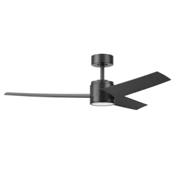
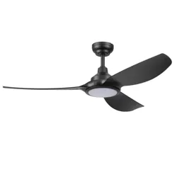
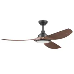
User Guide Ceiling Fan
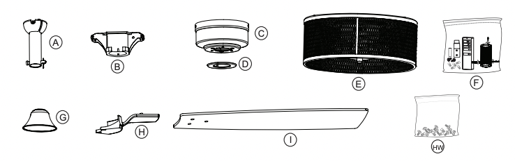
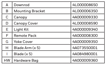
PACKAGE CONTENTS
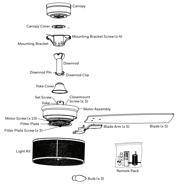
HARDWARE CONTENTS
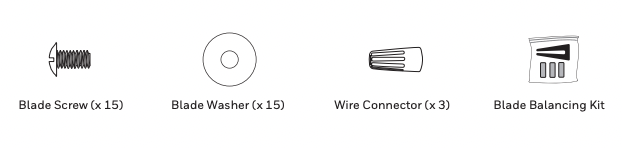
Note: Some extra hardware may be included. The quantity listed above is the number required for installation.
CARE AND MAINTENANCE
At least twice each year, lower the canopy to check the downrod assembly and tighten all screws on the fan. Clean the motor housing and blades with a soft brush or lint-free cloth to avoid scratching the finish.
Important: Shut off the main power supply before you begin any maintenance task. Do NOT use water or a damp cloth to clean the fan.
PREPARATION
Before beginning the assembly of this product, ensure all parts are present. Compare all parts with the package contents list and hardware contents list. If any part is missing or damaged, do not attempt to assemble the product.
Estimated assembly time: 2 hours
Tools required (not included): Electrical tape, Phillips Screwdriver, Safety Glasses, Step Ladder, and Wire Strippers.
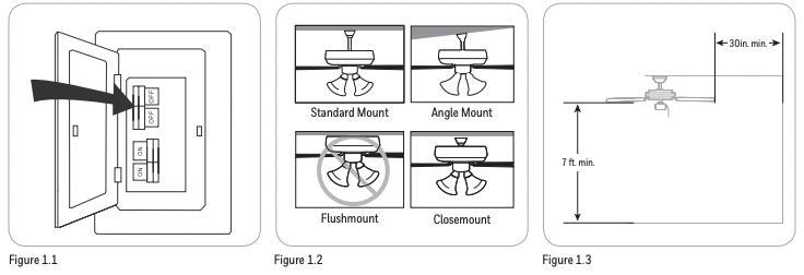
1. Turn off power to the fan at the breaker box and the wall switch (Figure 1.1). DANGER: Failure to disconnect the power supply prior to installation may result in serious injury or death.
2. Choose one of the following mounting options (Figure 1.2) :
- Standard Mount - best suited for ceilings 8 feet or higher. For very high ceilings, use a longer downrod (not included).
- Angle Mount - best suited for angled or vaulted ceilings. A longer downrod is sometimes necessary to ensure proper blade clearance. Ensure the ceiling angle is not steeper than 16 degrees.
- Flushmount Installation - not available for this model.
- Closemount Installation - best suited for ceilings 8 feet or lower.
3. Choose a suitable location - Ensure the blades will be at least 30 inches from any obstructions. Also check the downrod length to ensure the blades will be at least 7 feet above the floor (Figure 1.3).
INITIAL INSTALLATION
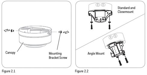
1. Loosen all four mounting bracket screws and completely remove the two screws from the round holes in the canopy. Then remove mounting bracket from the canopy and save the screws for later (Figure 2.1).
2. Install the mounting bracket to the outlet box (sold separately) using the screws and washers provided with the outlet box (Figure 2.2).
For CLOSEMOUNT INSTRUCTIONS, skip to page 6.
STANDARD OR ANGLE MOUNT INSTRUCTIONS
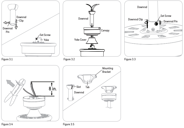
1. Remove the downrod pin and downrod clip from the downrod. Then partially loosen the set screws in the yoke at the top of the motor assembly (Figure 3.1).
2. Feed the fan wires through the yoke cover, canopy and downrod (Figure 3.2).
3. Slide the downrod into the yoke of the motor assembly. Align holes and reinstall the downrod pin and downrod clip and secure with the two set screws (Figure 3.3).
4. Depending on the length of downrod you use, you may want to cut the fan wires to simplify wiring. After pulling the wires all the way through the downrod, measure 8 inches of wire. Cut off the excess wire using wire cutters (not included) (Figure 3.4).
5. Install the ball end of the downrod into the opening of the mounting bracket (Figure 3.5). WARNING: Failure to align the slot in the ball with the tap on the mounting bracket may cause the fan to fall, which could result in injury or death.
Skip to FINAL INSTALLATION, page 6.
CLOSEMOUNT INSTRUCTIONS (optional)
1. Remove the canopy cover from the bottom of the canopy (Figura 4.1).
2. Remove the three Phillips-head closemount screws from the top of the motor assembly. Then align the canopy with the holes in the top of the motor assembly. The larger holes in the canopy will encompass the remaining screws. Secure the canopy to the top of the motor assembly with the previously removed closemount screws (Figura 4.2).
3. Raise the motor assembly and place the canopy on the hook of the mounting bracket to free hands during the wiring process (Figura 4.3). Then, insert the receiver in the mounting bracket with the flat side facing up.
 FINAL INSTALLATION
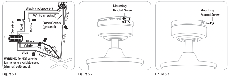
1. Use wire connnectors to connect household supply and receiver wires according to the diagram (Figure 5.1) and the following steps:
• Connect the green wire from the downrod and mounting bracket to the Bare/Green (ground) supply wire.
Note: Closemount installation does not use the downrod, so there will only be two Green wires to connect.
• Connect the Blue wire with the white label to the blue fan wire.
• Connect the Black wire with the white label to the black fan wire.
• Connect the White wire with the white label to the white fan wire.
• Connect the Red wire with the red label to the Black (live) supply wire.
• Connect the White wire with the red label to the White (neutral) supply wire.
2. Align the canopy over the loosened mounting bracket screws. Place the J-slot of the canopy onto the mounting bracket screws and rotate clockwise (Figure 5.2).
3. Secure the canopy with the two previously removed mounting bracket screws. Tighten all the mounting bracket screws securely (Figure 5.3).
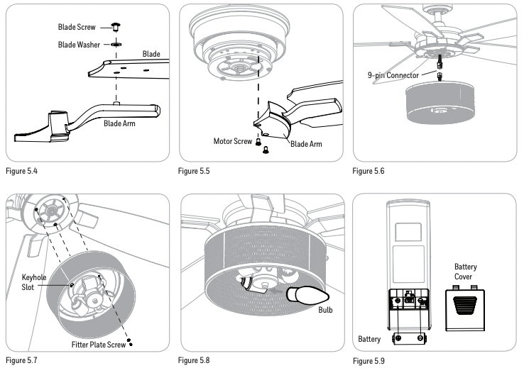
4. Partially insert the blade screws along with lock washer and blade washer through blade and into the blade arm. Tighten each blade screw starting with the one in the middle (Figure 5.4). Repeat this step for the remaining blades and blade arms (Figura 5.4).
5. Remove the 10 motor screws from the underside of the motor assembly. Then, install the blade arms to the underside of the motor assembly using the ten previously removed motor screws (Figure 5.5).
6. Remove one of the three fitter plate screws from the fitter plate and loosen the other two. Then, connect the 9-pin connector from the fan to the 9-pin connector from the light kit (Figure 5.6).
7. Lift the light kit and place the two keyhole slots in the light kit over the two loosened fitter plate screws. Turn the light kit clockwise and secure it to the fitter plate with the previously removed fitter plate screw. Tighten all three screws (Figure 5.7).
8. Install the three E26-base bulbs into the sockets of the light kit (Figure 5.8).
9. Remove the battery cover from the back of the remote and insert the 12-volt battery, noting polarity -- positive (+) to positive (+) and negative (-) to negative (-). Replace the battery cover. If battery is installed correctly, the LED indicator on the front of the remote transmitter should illuminate when any button is pushed (Figure 5.9).
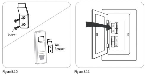
10. If desired, the wall bracket in remote pack can be installed to a wall using the provided mounting screws. The remote can be stored in the mounting bracket for easy access (Figure 5.10).
11. Turn on power to fan at breaker box and the wall switch (Figure 5.11). Assembly is complete.
OPERATING INSTRUCTIONS
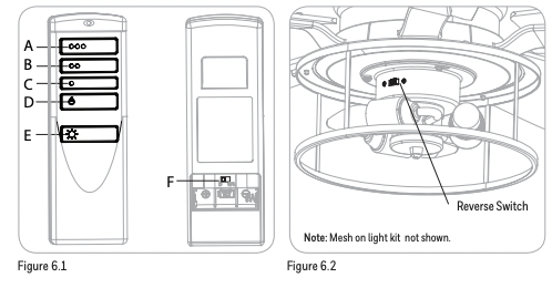
1. To operate the fan using remote control, press and release the following buttons:
- A - High fan speed
- B - Medium fan speed
- C - Low fan speed
- D - Turns the fan off. Press and hold this button for 5 seconds to enter Light Delay Off mode, which will turn off light after one minute. The LED indicator on the remote control will flash four times to confirm mode setting.
- E - Light Control: Dimmable Bulbs - Press light control to turn lights off and on. Press and hold light control to dim or brighten the lights. Non-dimmable Bulbs -Turns the lights on and off. Note: The dimmer function does not work with nondimmable bulbs.
- F - D/CFL Switch: Located inside the battery compartment in remote transmitter. Button must remain in the “D” position at all times for this item. (Figure 6.1).
2. Use the reverse switch located on the light kit to optimize your fan for seasonal performance. In warmer weather, push the reverse switch left which results in downward airflow creating a wind chill effect. In cooler weather, push the reverse switch right which results in upward airflow that will help move hot air of the ceiling (Figure 6.2).
TROUBLESHOOTING
If you experience any faults, please check the Troubleshooting section below. If a problem cannot be remedied or you are experiencing difficulty in installation, please contact Customer Service: 1-877-361-3883.
Warning: Shut off the power supply before you begin any maintenance task.
The fan does not move.
- 1. Firmly push the reverse switch completely left or right.
- 2. Make sure the wall switch is turned on.
- 3. Turn the power on or check the fuse (breaker).
- 4. Turn the power off and check all connections at the ceiling outlet box.
The fan is noisy.
- 1. Check and tighten all screws that hold the fan blades to the blade arms and the motor.
- 2. Replace the cracked blade.
- 3. Do not use a full range dimmer switch to control the fan speed.
- 4. Ensure the outlet box is secured to the building structure.
- 5. Ensure the mounting bracket is secured to the outlet box and that the screws are tight.
The fan wobbles excessively.
- 1. Check and tighten all screws that hold the fan blades to the blade arms and the blade arms to the motor.
- 2. Switch one blade with a blade from the opposite side, or balance the fan using the blade balancing kit.
- 3. Turn off the power. Loosen the canopy and verify that the mounting bracket is secure to the electrical outlet box. The bracket must be flush without movement against the outlet box. Verify the outlet box is secure.
- 4. Use a longer downrod (sold separately) or move the fan to another location.
- 5. Lift up the yoke cover and tighten the set screws on the yoke until secure.
The fan operates correctly but the lights are not working.
- 1. Ensure the single-pin connectors are properly secured.
- 2. Turn the power off and check all connections at the ceiling outlet box.
Remote control does not work.
- 1. Turn off the main power, then turn it back on. Within 30 seconds, press and hold the high and low speed buttons on the remote at the same time for 5 seconds. The LED indicator will flash 3 times, signaling a successful synchronization. Once complete, the fan will start on the low speed with the light (if applicable) off.
- 2. Insert new 12V battery in battery compartment of the remote control.
- 3. If there are several fans in close proximity, turn power off to other fans and re-sync the remote.
REPLACEMENT PARTS LIST
For replacement parts, call our customer service department (1-877-361-3883). Monday-Thursday 8am - 6pm, Friday 8am - 5pm, Eastern Standard Time.
The Honeywell Trademark is used under license from Honeywell International Inc ™.
Honeywell International Inc. makes no representations or warranties with respect to this product.
LIMITED LIFETIME WARRANTY
Set forth below, the manufacturer, Hong Kong China Electric Appliance Company (HKC) warrants the fan motor for this ceiling fan to be free from defects in workmanship and material for the life of the product. Also, subject to the limitations below, HKC warrants all ceiling fan parts (“ceiling fan parts” excludes the motor and parts made in whole or in part with glass) to be free from defects in workmanship and material for a period of one year after the date of purchase by the original purchaser at retail.
All claims must be made by the original purchaser, whether such purchaser purchased the product through a store or contractor. Ceiling fan part defects must be reported within the first year from the date of purchase. Parts made in whole or in part with glass and the finishes of metal and other surfaces are not warranted.
Purchasers are responsible for all costs of removing and reinstalling the product. Any damage to any part caused by ordinary wear and tear, accident, misuse, or improper installation, is not covered by this warranty. HKC assumes no responsibility whatsoever for fan installation. Any service performed by a non-licensed electrician will render the warranty invalid.
HKC’s sole responsibility shall be to repair or replace the motor, parts, or product within the terms stated above. HKC shall not be liable for any loss or damage of any kind, including any incidental or consequential damages resulting directly or indirectly, from any breach of warranty, express or implied, or any other failure of this product. Some states do not allow the exclusion or limitation of incidental or consequential damages so this limitation may not apply to you.
If the original purchaser ceases to own the fan, this warranty is voided.
Should the purchaser encounter a problem with your fan related to defects in workmanship or materials within the warranty period associated with the defective part, HKC agrees to replace the defective part without charge, or at its option, to replace the ceiling fan with a comparable or superior model.
HKC’s warranties are limited to the written warranties set out in this HKC ceiling fan limited lifetime warranty. All other express and implied warranties, including, without limitation, the implied warranty of fitness for a particular purpose and the implied warranty of merchantability are disclaimed. Some states do not allow the disclaimer of implied warranties, so this disclaimer may not apply to you.