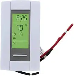
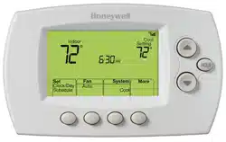
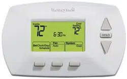
User manual Thermostat
Installation tips
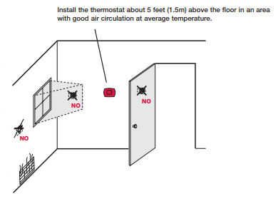
Do not install in locations where the thermostat can be affected by:
- Drafts or dead spots behind doors and in corners
- Hot or cold air from ducts
- Sunlight or radiant heat from appliances
- Concealed pipes or chimneys
- Unheated/uncooled areas such as an outside wall behind the thermostat
Pre-installation checklist
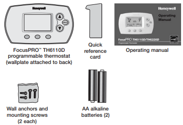
Package contents
Check to make sure your package includes the following items:
Wallplate installation
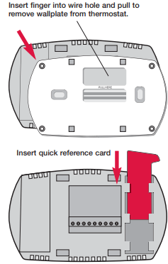
Remove the wallplate from the thermostat as shown at left, then follow directions below for mounting.
1 Insert quick reference card in slot in back of thermostat.
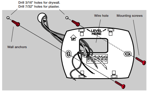
2 Pull wires through wire hole.
3 Position wallplate on wall, level and mark hole positions with pencil.
4 Drill holes at marked positions as shown below, then tap in supplied wall anchors.
5 Place wallplate over anchors, insert and tighten mounting screws.
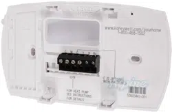
Wiring
CAUTION: ELECTRICAL HAZARD. Can cause electrical shock or equipment damage. Disconnect power before wiring.
NOTES
R & Rc terminals
In single-transformer system, leave metal jumper in place between R & Rc. Remove metal jumper if two-transformer system.
C terminal
The C (common wire) terminal is optional when thermostat is powered by batteries.
W (O/B) terminal
If thermostat is configured for a heat pump in the Installer Setup, configure changeover valve for cool (“O” factory setting) or heat (“B”).
Wire specifications
Use 18- to 22-gauge thermostat wire. Shielded cable is not required.
Wiring
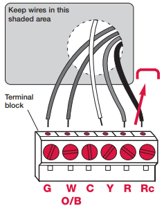
1 Loosen screw terminals, insert wires into terminal block, then re-tighten screws.
2 Push excess wire back into the wall opening. Keep wires in shaded area as shown at left.
3 Plug the wall opening with nonflammable insulation to prevent drafts from affecting thermostat operation.
Terminal Designations
G Fan relay.
W O/B Heat relay or changeover valve terminal for heat pumps.
C Common wire from secondary side of cooling system transformer.
Y Compressor contactor.
R Heating power. Connect to secondary side of heating system transformer.
Rc Cooling power. Connect to secondary side of cooling system transformer.
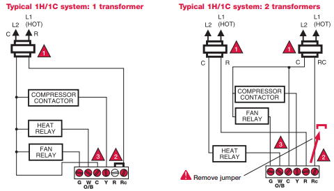
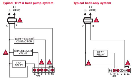
Wiring diagrams
Power supply. Provide disconnect means and overload protection as required.
Factory-installed jumper. Remove for 2-transformer systems only.
Optional 24VAC common connection.
In Installer Setup, set system type to Heat Only.
In Installer Setup, set system type to Heat Pump & changeover valve to 0 or B.
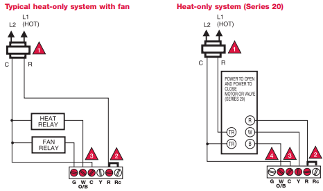
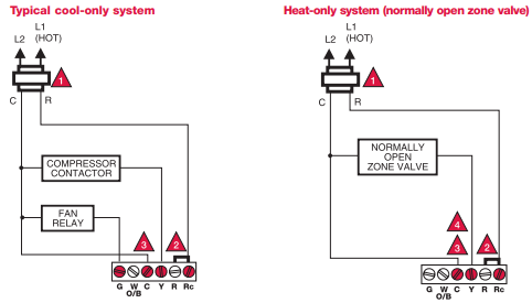
Power options & mounting
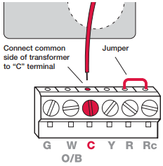
AC Power
The thermostat can be powered by 24 VAC power, or by batteries.
To wire the thermostat for AC power, connect the common side of the cooling transformer to the “C” terminal as shown at left.
Important: Remove R/Rc jumper for 2-transformer systems only. (See wiring diagram on page 5.)
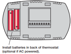
Battery Power
The thermostat can be powered by batteries alone or, if used with AC power, can provide backup power. During power interruptions the batteries will save time/day settings and power the display.
After installation, batteries can be changed without removing the thermostat from the wall (see page 11)
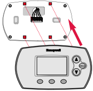
To Mount Thermostat
Align the 4 tabs on the wallplate with corresponding slots on the back of the thermostat, then push gently until the thermostat snaps in place.
Installer setup
Follow the procedure below to configure the thermostat to match the installed heating/cooling system, and customize feature operation as desired.
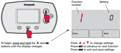
1 System type
0 Gas, oil or electric heat with air conditioning
1 Heat pump
2 Heat only (2-wire systems/power to open & close zone valves/ normally open zone valves)
3 Heat only with fan
4 Cool only
2 Changeover valve (O/B terminal)
0 Changeover valve (O/B terminal energized in cooling)
1 Changeover valve (O/B terminal energized in heating)
3 Fan control (heating)
0 Gas or oil furnace — equipment controls fan in heating
1 Electric furnace — thermostat controls fan in heating
5 Heating cycle rate (CPH: cycles/hour)
5 For gas or oil furnaces of less than 90% efficiency
1 For steam or gravity systems
3 For hot water systems & furnaces of over 90% efficiency
9 For electric furnaces
[Other cycle rate options: 2, 4, 6, 7, 8, 10, 11 or 12 CPH]
9 Compressor cycle rate (CPH)
3 Recommended for most compressors
[Other cycle rate options: 1, 2, 4, 5 or 6 CPH]
12 System setting adjustment
0 Manual changeover (Heat/Cool/Off)
1 Auto changeover (Heat/Cool/Auto/Off) **See page 10
2 Auto changeover only (Auto) **See page 10
13 Adaptive Intelligent Recovery™
1 On **See page 10
0 Off
14 Temperature display
0 Fahrenheit
1 Celsius
15 Compressor protection
5 Five-minute compressor off time **See page 10
[Other options: 0, 1, 2, 3 or 4-minute off time]
16 Schedule format
0 5/2 (programmable weekdays and weekends)
1 5/1/1 (weekdays, Saturday & Sunday programmable)
Installer system test
Follow the procedure below to test the heating, cooling and fan.
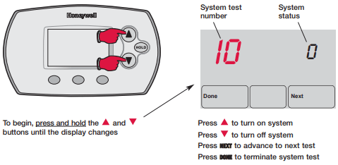
10 Heating system
0 Heat and fan turn off.
1 Heat turns on. Fan also turns on immediately if Function 1 or 3 is set to “1” (see page 8).
30 Cooling system
0 Compressor and fan turn off.
1 Compressor and fan turn on.
40 Fan system
0 Fan turns off.
1 Fan turns on.
70 Thermostat information (for reference only)
71 Software revision number (major revisions)
72 Software revision number (minor revisions)
73 Configuration identification code (major)
74 Configuration identification code (minor)
75 Production configuration date code (week)
76 Production configuration date code (year)
Auto Changeover (Setup Function 12)
Auto Changeover is a feature used in climates where both air conditioning and heating are used on the same day.When the system is set to Auto, the thermostat automatically selects heating or cooling depending on the indoor temperature.
Heat and cool settings must be at least 3 degrees apart.The thermostat will automatically adjust settings to maintain this 3-degree separation (called “deadband”).
The 3-degree separation between heating and cooling set temperatures is fixed, and cannot be changed.
Adaptive Intelligent Recovery™ (Setup Function 13)
Adaptive Intelligent Recovery eliminates guesswork when setting your schedule. It allows the thermostat to “learn” how long your furnace and air conditioner take to reach the temperature you want.
Just set your program schedule to the time you want the house to reach your desired temperature.The thermostat then turns on the heating or cooling at just the right time to reach your scheduled temperature at your scheduled time.
For example: Set the Wake time to 6 am, and the temperature to 70°.The heat will come on before 6 am, so the temperature is 70° by the time you wake at 6.
Built-in compressor protection (Setup Function 15)
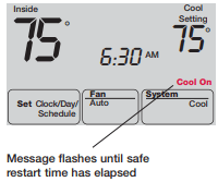
This feature helps prevent damage to the compressor in your air conditioning or heat pump system.
Damage can occur if the compressor is restarted too soon after shutdown.This feature forces the compressor to wait for a few minutes before restarting.
During the wait time, the message Cool On or Heat On (heat pumps only) will flash on the display.When the safe wait time has elapsed, the message stops flashing and the compressor turns on.
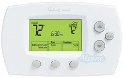
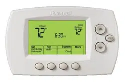
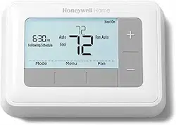
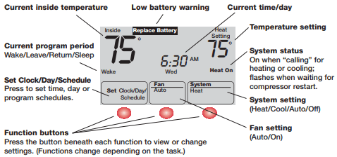
Quick reference to controls
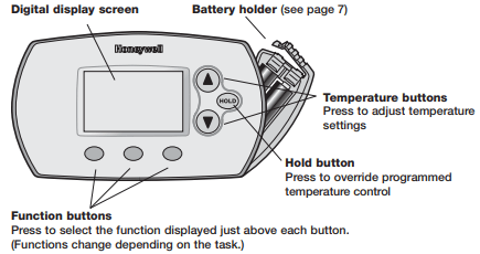
Quick reference to display screen
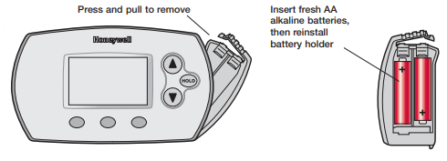
Battery replacement
In case of difficulty
If you have difficulty with your thermostat, please try the suggestions below. Most problems can be corrected quickly and easily.
Display is blank
- Check circuit breaker and reset if necessary.
- Make sure power switch at heating & cooling system is on.
- Make sure furnace door is closed securely.
- If thermostat is battery powered, make sure fresh AA alkaline batteries are correctly installed (see page 7).
Temperature settings do not change
Make sure heating and cooling temperatures are set to acceptable ranges:
- Heat: 40° to 90°F (4.5° to 32°C).
- Cool: 50° to 99°F (10° to 37°C).
Heating system does not respond (“Heat On” appears on screen)
- Check for 24 Vac at the equipment on the secondary side of the transformer between power and common. If voltage is not present, check the heating equipment to find the cause of the problem.
- Check for 24 Vac between the heat terminal (W) and the transformer common. If 24 Vac is present, the thermostat is functional. Check the heating equipment to find the cause of the problem.
- Check for loose or broken wires between the thermostat and the heating equipment.
Cooling system does not respond (“Cool On” appears on screen)
- Check for 24 Vac at the equipment on the secondary side of the transformer between power and common. If voltage is not present, check the cooling equipment to find the cause of the problem
- Check for 24 Vac between the cooling terminal (Y) and the transformer common. If 24 Vac is present, the thermostat is functional. Check the cooling system to find the cause of the problem.
- Check for loose or broken wires between the thermostat and the cooling equipment.
Fan does not turn on in a call for heat
- Check Installer Setup, Function 3 (Fan Control), to make sure the fan control is properly set to match the type of system (see page 8).
Heat pump issues cool air in heat mode, or warm air in cool mode
- Check Installer Setup, Function 2 (Changeover Valve), to make sure it is properly configured for your system (see page 8).
Heat/cool both on at same time, or heat does not turn off
- Check Installer Setup, Function 1 (System Type), to make sure it is set to match the installed heating/cooling equipment (see page 8).
- Check to make sure heating and cooling wires are not shorted together.
Heating equipment is running in cool mode
- Check Installer Setup, Function 1 (System Type), to make sure it is set to match the installed heating/cooling equipment (see page 8).
Cannot change system setting to “Heat”
- Check Installer Setup, Function 1 (System Type), to make sure it is set to match the installed heating equipment (see page 8).
- Change Installer Setup, Function 12 (System Setting) to Manual or Auto Changeover (see page 8).
Cannot change system setting to “Cool”
- Check Installer Setup, Function 1 (System Type), to make sure it is set to match the installed cooling equipment (see page 8).
- Change Installer Setup, Function 12 (System Setting) to Manual or Auto Changeover (see page 8).
“Heat On” is not displayed
- Change the System Setting to Heat, and set the temperature level above the current room temperature.
“Cool On” is not displayed
- Change the System Setting to Cool, and set the temperature level below the current room temperature.
“Cool On” or “Heat On” is flashing
- Compressor protection timeout is engaged. Wait 5 minutes for the system to restart safely, without damage to the compressor.