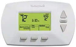
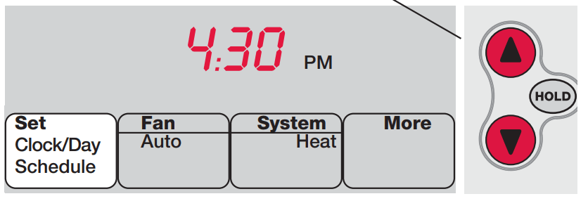
1. Press SET CLOCK/DAY/SCHEDULE, then press or to set clock.
2. Press SET DAY, then press or to select the day of week.
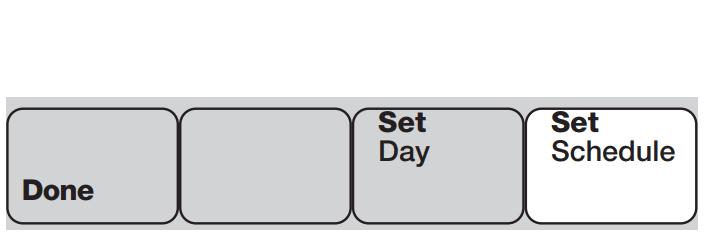
3. Press DONE to save.
Press SET DAY, then select current day
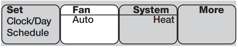
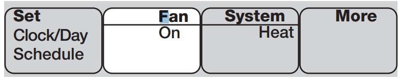
Select the fan setting
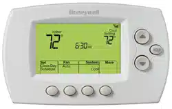
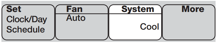
Press FAN to select Auto or On. In “Auto” mode (the most commonly used setting), the fan runs only when the heating or cooling system is on. If set to “On,” the fan runs continuously.
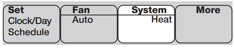
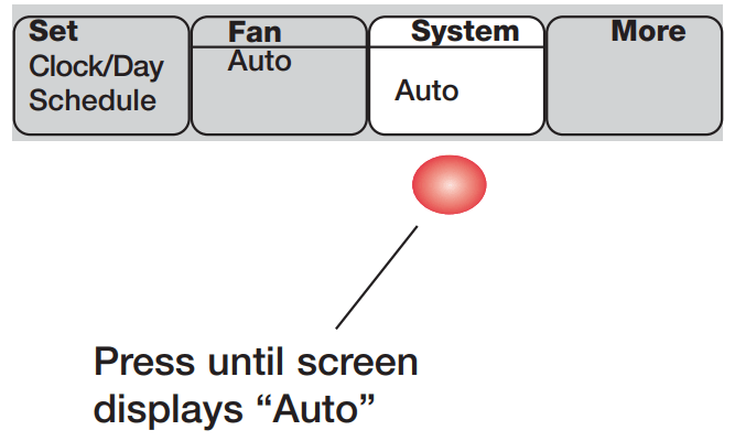
Select the system setting
Press SYSTEM to select:
• Heat: Thermostat controls only the heating system.
• Cool: Thermostat controls only the cooling system.
• Off: All systems are off.
• Auto: Thermostat automatically selects heating or cooling depending on the indoor temperature.
• Em Heat (only for heat pumps with auxiliary heat): Thermostat controls Emergency and Auxiliary Heat. Compressor is locked out.
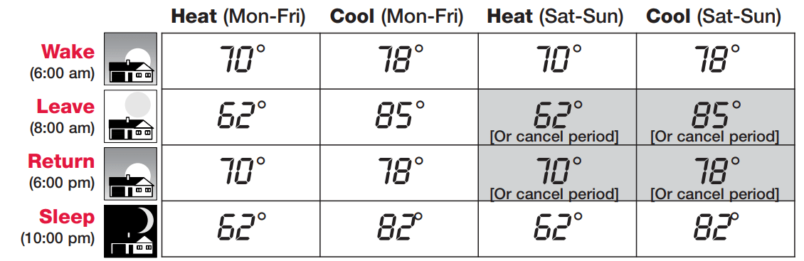
Energy-saving settings for maximum cost savings
This thermostat is pre-set to use energy-saving program settings. We recommend these settings, since they can reduce your heating/cooling expenses by as much as 33%. (See next page to adjust times and temperatures of each time period.)
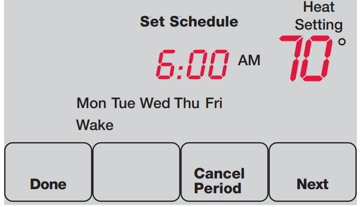
To adjust program schedules
1. Press SET CLOCK/DAY/SCHEDULE, then SET SCHEDULE.
2.. Press or to set your weekday Wake time (Mon-Fri), then press NEXT.
3. Press or to set the temperature for this time period, then press NEXT.
4. Set time and temperature for the next time period (Leave). Repeat steps 2 and 3 for each weekday time period.
5. Press NEXT to set weekend time periods (Sat-Sun), then press DONE to save & exit.
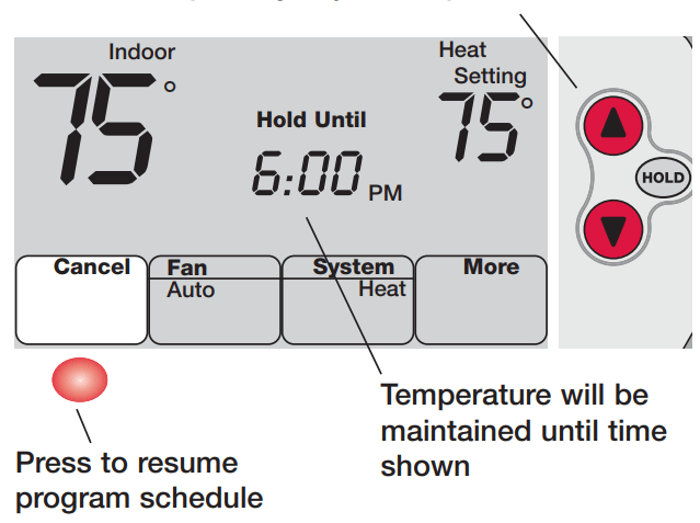
Program schedule override (temporary)
Press to temporarily adjust temperature
Press or to immediately adjust the temperature. This will temporarily override the temperature setting for the current time period.
The new temperature will be maintained only until the next programmed time period begins (see page 8).
To cancel the temporary setting at any time, press CANCEL.
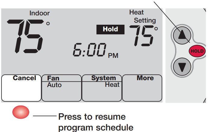
Program schedule override (permanent)
Press to permanently adjust temperature
Press HOLD to permanently adjust the temperature. This will override the temperature settings for all time periods.
The “Hold” feature turns off the program schedule and allows you to adjust the thermostat manually, as needed.
Whatever temperature you set will be maintained 24 hours a day, until you manually change it, or press CANCEL to resume the programmed schedule.
Auto Changeover (heat/cool)
Auto Changeover is a feature used in climates where both air conditioning and heating are often used on the same day. When the system is set to Auto, the thermostat automatically selects heating or cooling depending on the indoor temperature.
Heat and cool settings must be at least 3 degrees apart. The thermostat will automatically adjust settings to maintain this 3-degree separation.
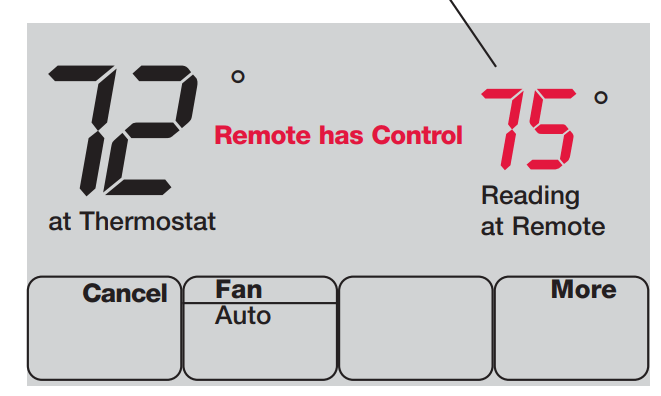
Remote control
Temperature is measured at location of remote control
The optional remote control can act as a mobile thermostat, to maintain a comfortable temperature as you move from room to room.
When the system is responding to temperatures measured at the Remote, the thermostat will display Remote has Control.
Press CANCEL to restore temperature control to the thermostat (the system will only respond to temperatures measured at the thermostat).
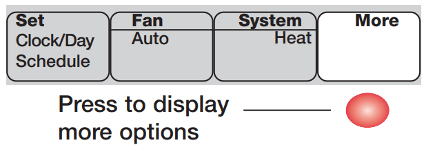
Additional features
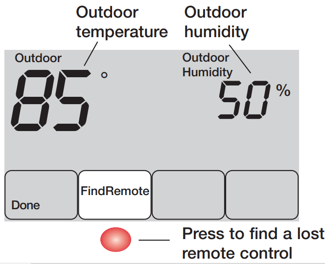
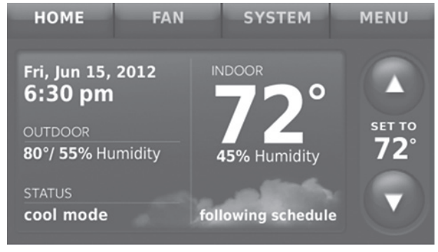
To display outdoor climate
If you have an outdoor air sensor, press MORE to display the current outdoor temperature and humidity. Press DONE to exit.
To find a lost remote control
If you misplace a remote control, press MORE, then FIND REMOTE. The remote will beep for two minutes to help you locate it. Press anywhere on the display screen to stop the beeping.
Special features
Built-in compressor protection: This feature helps prevent damage to the compressor in your air conditioning or heat pump system. Damage can occur if the compressor is re-started too soon after shutdown. This feature forces the compressor to wait for a few minutes before restarting.
During the wait time, the display will flash the message Cool On (or Heat On if you have a heat pump).
Adaptive Intelligent Recovery: This feature eliminates guesswork when setting your schedule. It allows the thermostat to “learn” how long your furnace and air conditioner take to reach programmed temperature settings, so the temperature is reached at the time you set.
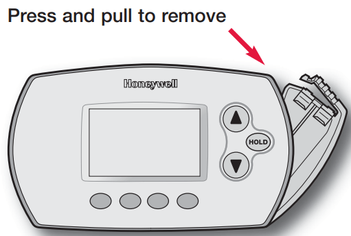
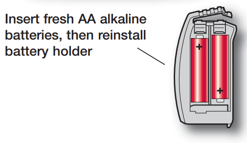
Battery replacement (thermostat)
Install fresh batteries when the REPLACE BATTERY warning begins flashing. The warning flashes about two months before the batteries are depleted.
Remove the battery holder and install 2 fresh AA alkaline batteries.
After batteries are installed, the thermostat will automatically restore communication with the wireless network within a few minutes.
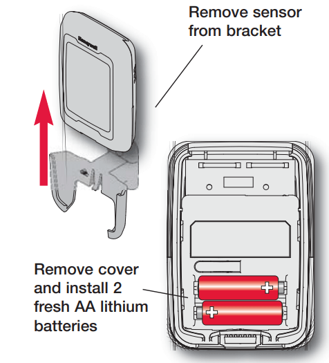
Battery replacement (outdoor air sensor)
Replace outdoor sensor batteries when the REPLACE BATTERY OUTDOOR warning begins flashing on the thermostat. The warning flashes about two months before the batteries are depleted.
Remove the sensor from the bracket, remove the cover and install 2 fresh AA lithium batteries.
After batteries are installed, the sensor will automatically restore communication with the wireless network within a few minutes.
Installation
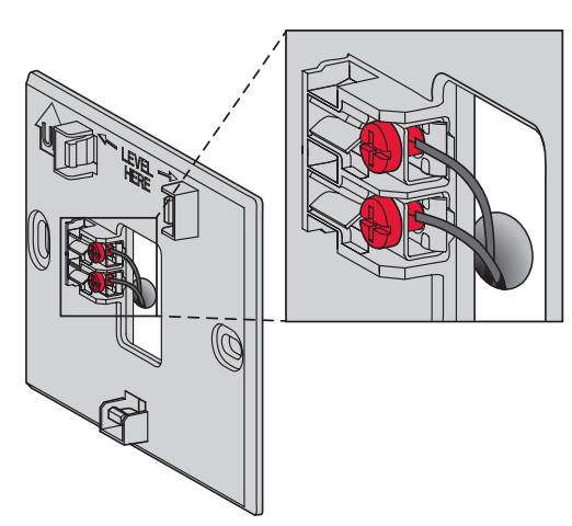
1. Install thermostat
Prestige/VisionPRO with RedLINK: Mount the thermostat and wire to C and R terminals of the Equipment Interface Module (EIM), or to a separate 24 volt transformer (not provided).
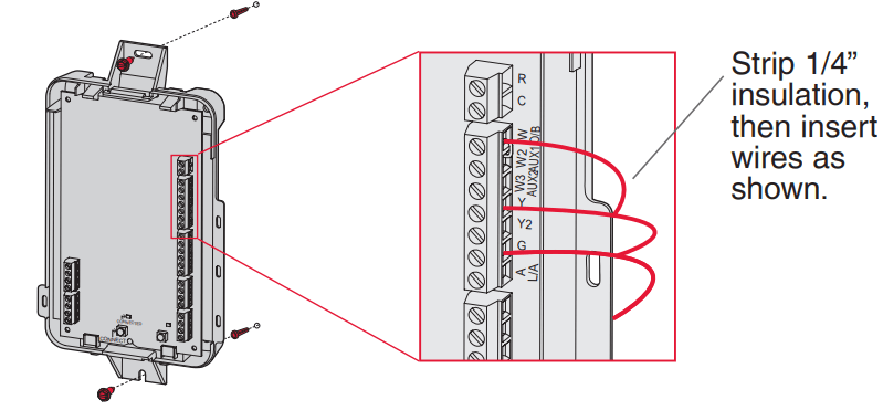
2. Install equipment interface module
Use screws & anchors as appropriate for the mounting surface. Mount the EIM near the HVAC equipment, or on the equipment itself.
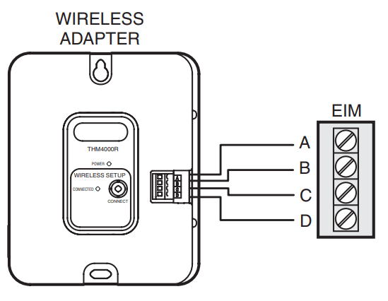
If an EIM is mounted inside a metal cabinet, it is recommended to use a THM4000R1000 Wireless Adapter for extended wireless range. Mount the Wireless Adapter outside the metal cabinet and connect to the ABCD terminals at the EIM.
3. Power optional RedLINK accessories
3.1 Install batteries in RedLINK accessories.
• Portable Comfort Control
• Wireless Outdoor Sensor*
• Wireless Indoor Sensor*
• Wireless Entry/Exit Remote*
• Wireless Vent and Filter Boost Remote*
* Requires setup. See Installer Setup options in Step 4.5.
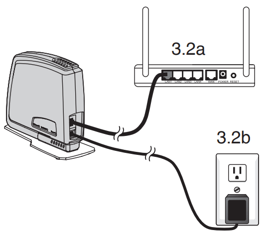
3.2 Connect gateway to internet and connect to power.
3.2a Connect RedLINK Internet Gateway to router or modem with Ethernet cable (RJ45).
3.2b Connect gateway’s power cord to an electrical outlet that is not controlled by a wall switch.
4. Performing initial setup
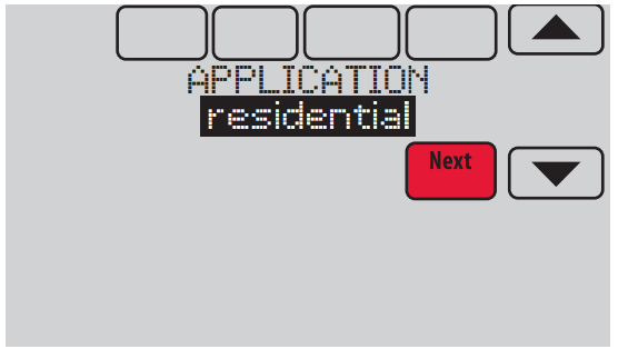
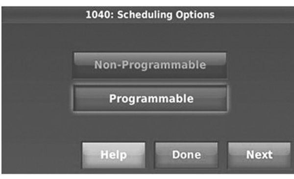
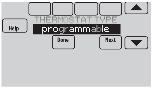
Initial setup options define the type of system you are installing:
• Residential or commercial
• Non-zoned or zoned
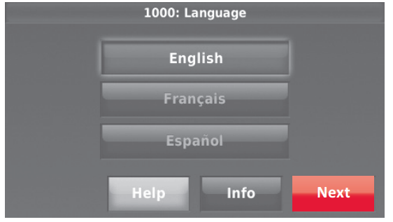
4.1 Follow prompts on the screen to select appropriate options.
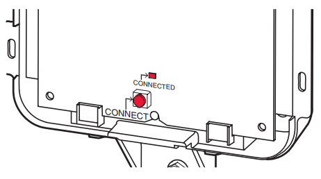
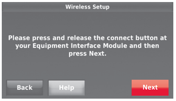
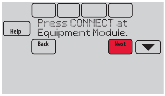
4.2 Link the thermostat to the equipment interface module.
4.2a Press and quickly release the CONNECT button on the EIM. Make sure the “Connected” light is flashing green.
• Green Flashing: In Listening Mode - system is ready to add RedLINK devices.
• Green Steady: RedLINK devices are communicating.
• Red: RedLINK device(s) are NOT communicating. Check EIM and RedLINK devices.
4.2b While the “Connected” light is flashing green on the EIM, press Next on the thermostat. After a short delay, the screen will show the thermostat is connected.
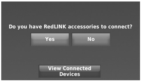
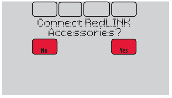
4.3 When you see the prompt Do you have RedLINK accessories to connect? Touch Yes or No.
• If you select Yes, you will be prompted to Press Connect on all new accessories. Continue to Step 4.4.
• If you select No, continue to Step 4.5.
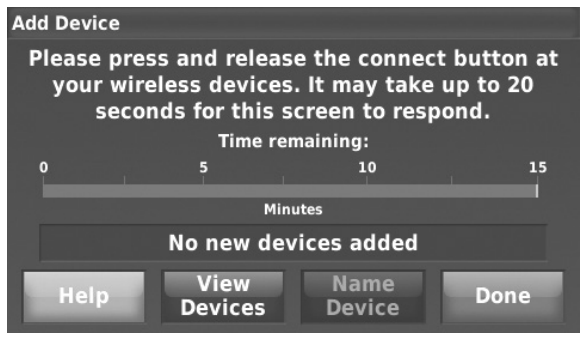
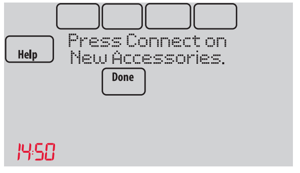
4.4 Connect each RedLINK accessory.
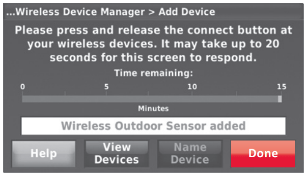
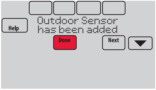
4.4a While the Add Device screen is displayed (listening mode), press and quickly release the CONNECT button on each new RedLINK accessory.
4.4b After a short delay (up to 20 seconds), check the thermostat to confirm the connection of each RedLINK accessory.
4.4c Touch Done at the thermostat after all new RedLINK accessories are connected.
4.5 Finish the initial setup.
Finish the setup by selecting the desired options. Touch Done after you select the last option you want to change.
The thermostat now displays its Home screen and the thermostat setup is complete.
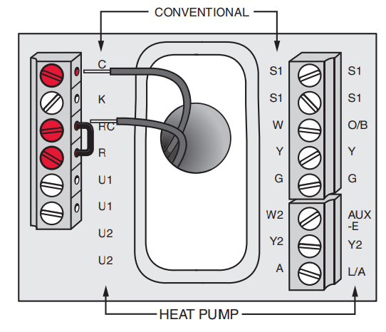
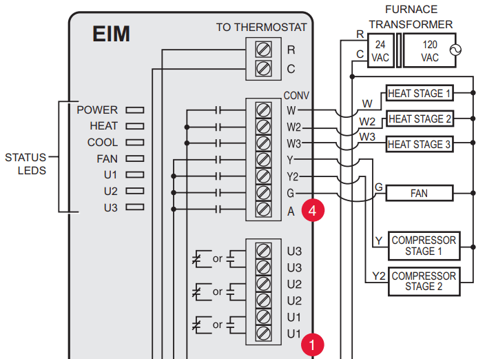
EIM wiring guide — conventional systems
Typical wiring of a conventional system with up to 3-stage heat and 2-stage cool with one transformer.
See guides on following pages for thermostat wiring and geothermal radiant heat wiring.
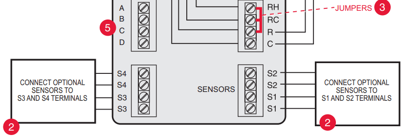
Wire a maximum of 4 sensors using the S1-S4 terminals. S1-S4 terminals can be connected to an indoor sensor, outdoor sensor, discharge sensor, return sensor, dry contact device to display an alert or an occupancy sensor for remote setback.
Remove jumper(s) if using separate transformers.
See Economizer wiring section.
Connect wireless adapter to ABCD for extended wireless range.
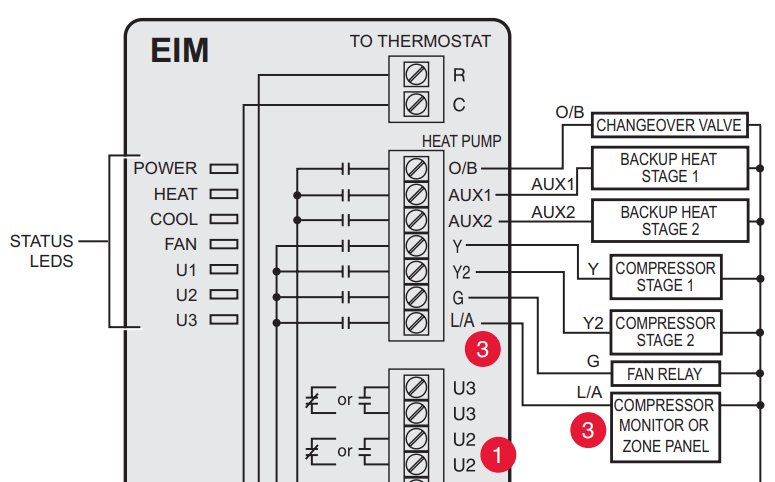
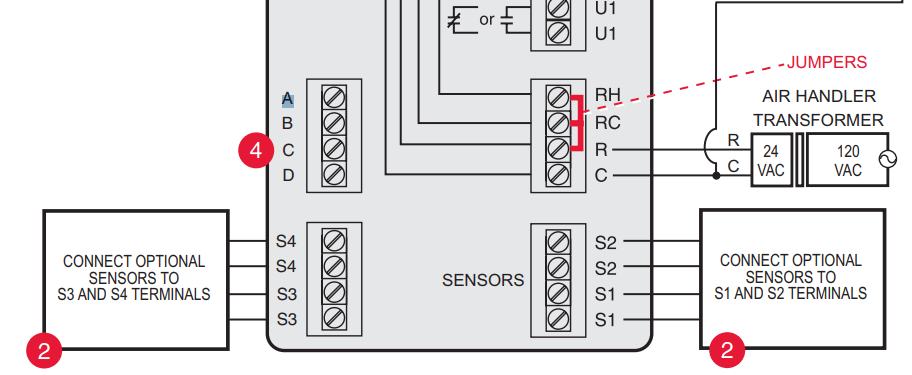
EIM wiring guide — heat pump systems
Typical wiring of a heat pump system with up to four-stage heat and two-stage cool with one transformer.
See guides on following pages for thermostat wiring and geothermal radiant heat wiring.
Wire a maximum of 2 sensors using the S1-S4 terminals. S1-S4 terminals can be connected to an indoor sensor, outdoor sensor, discharge sensor, return sensor, dry contact device to display an alert or an occupancy sensor for remote setback.
L/A terminal sends continuous output when thermostat is set to EM HEAT mode,except when set up for Economizer or TOD. See Economizer wiring section.
Connect wireless adapter to ABCD for extended wireless range
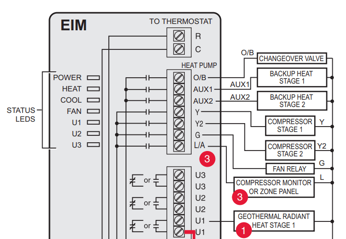
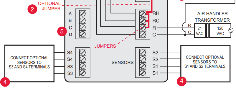
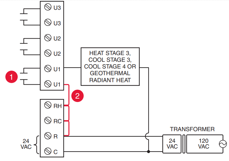
EIM wiring guide — geothermal radiant heat
Typical wiring for geothermal radiant heat, geothermal forced-air, and backup heat with one transformer.
U1, U2 or U3 terminals must be used for geothermal radiant heat. Thermostat allows 2 stages of radiant heat—geothermal (stage 1) and boiler (stage 2).
“U” terminals are normally open dry contacts when set up for geothermal radiant heat. You must install a field jumper if radiant heat is powered by system transformer. Do NOT install a field jumper if radiant heat has its own transformer.
L/A terminal sends continuous output when thermostat is set to EM HEAT mode except when set up for Economizer or TOD. See Economizer wiring section. EIM wiring guide — geothermal radiant heat
Wire a maximum of 2 sensors using the S1-S4 terminals. S1-S4 terminals can be connected to an indoor sensor, outdoor sensor, discharge sensor, return sensor, dry contact device to display an alert or an occupancy sensor for remote setback.
Connect wireless adapter to ABCD for extended wireless range.
Using universal relays to control heating or cooling
U1/U2/U3 terminals are normally open dry contacts when set up for a stage of heating or cooling.
You must install a field jumper if the stage of heating or cooling is powered by system transformer. Do NOT install a field jumper if the stage of heating has its own transformer.
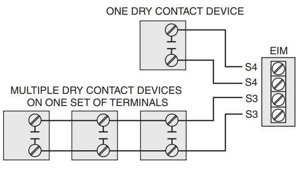
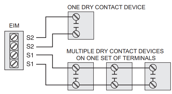
Dry contact alerts
If you are not using the S1–S4 terminals on the EIM, you can connect them to a dry contact device to display an alert. Dry contact alerts include Full Drain Pan, Dirty Filter, Water Leak, System Shutdown, Service Needed, Fan Failure and Custom Alert. Dry contact device can be normally open (shown in diagram) or normally closed
NOTE: You can connect multiple Dry Contact devices in parallel to the S1–S4 terminals.
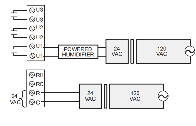
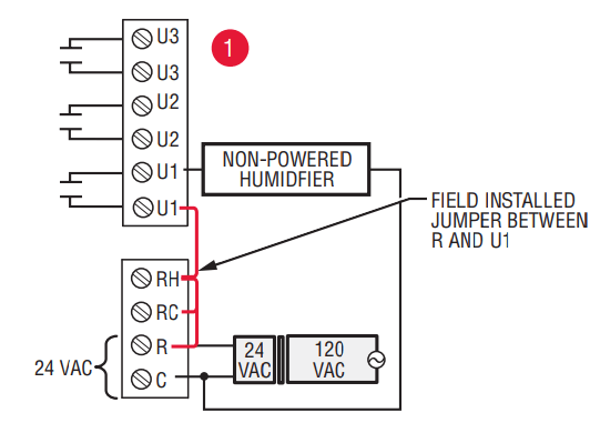
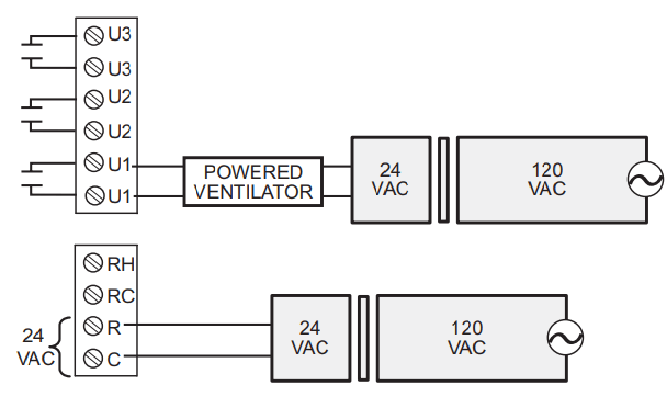
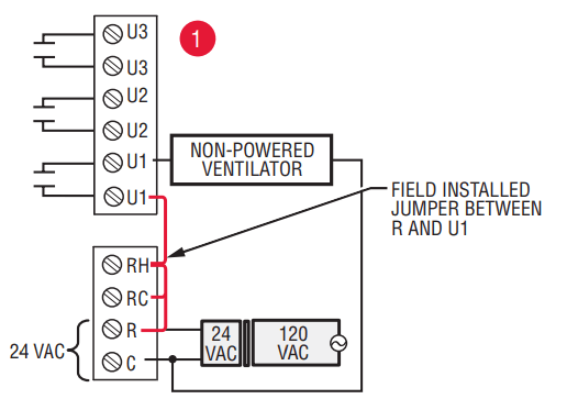
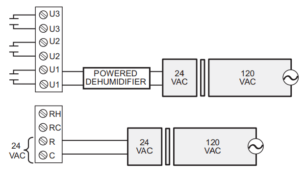
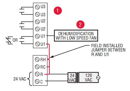
Wiring humidification, dehumidification and ventilation
"U" terminals can be used for humidification, dehumidification or ventilation.
Typical hookup of powered humidifier
Typical hookup of non-powered humidifier
Typical hookup of powered ventilation
Typical hookup of non-powered ventilation
Typical hookup of powered dehumidifier (whole house dehumidifier)
Typical hookup of variable speed blower for dehumidification in low speed
Any combination of universal relays (U1, U2, U3) can be used. They are set in the thermostat installer setup.
Wire the universal EIM relay to the low speed fan for dehumidification control at the equipment. The EIM relay can be set to be normally open or normally closed in the thermostat installer setup
Normally open, dry contacts
Normally closed, dry contacts
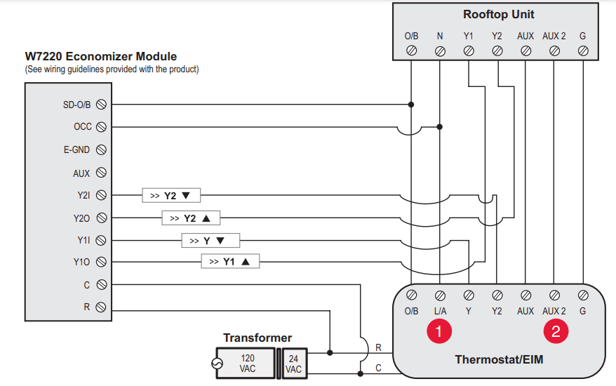
Economizer Module wiring guides
Typical wiring of a W7220 Economizer Module for a heat pump system, using a VisionPRO with RedLINK thermostat or Equipment Interface Module.
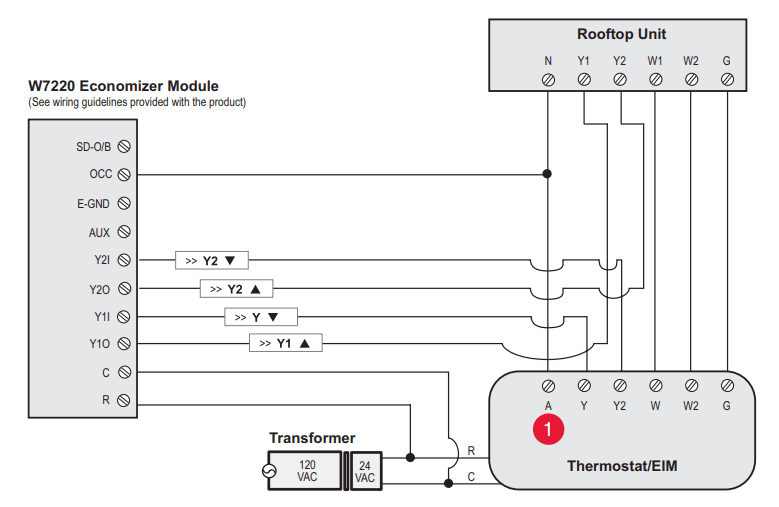
Typical wiring of a W7220 Economizer Module for a conventional system, using a VisionPRO with RedLINK thermostat or Equipment Interface Module.
"A" or "L/A" terminal must be configured for Economizer in the installer setup. These terminals are powered by the cooling transformer (Rc terminal).
Terminal AUX 2 is present only on the Equipment Interface Module.
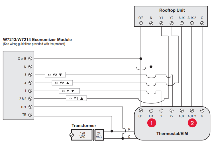
Economizer Module wiring guides
Typical wiring of a W7213/W7214 Economizer Module for a heat pump system, using a VisionPRO with RedLINK thermostat or Equipment Interface Module.
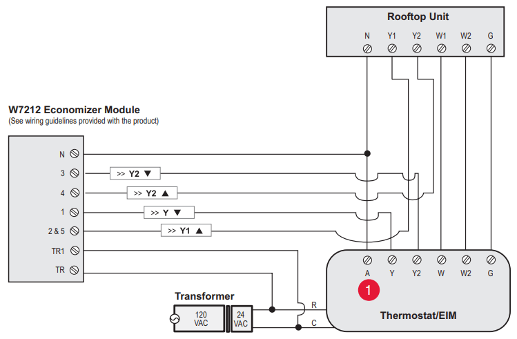
Typical wiring of a W7212 Economizer Module for a conventional heating system, using a VisionPRO with RedLINK thermostat or Equipment Interface Module.
"A" or "L/A" terminal must be configured for Economizer in the installer setup. These terminals are powered by the cooling transformer (Rc terminal).
Terminal AUX 2 is present only on the Equipment Interface Module.
To replace the Equipment Interface Module (EIM)
When you replace an EIM, you must reset the RedLINK accessories before connecting them to the new thermostat. Follow the instructions below:
At the Portable Comfort Control:
Press and hold the blank space (or arrow) in the lower right hand corner of the screen until the display changes (hold for about 4 seconds). Press REMOVE, then YES to disconnect from the old thermostats. To reconnect the thermostat, go to Step 4.
At the Indoor Sensor, RedLINK Internet Gateway, Entry/Exit Remote, Vent-Filter Boost Remote or TrueSTEAM Wireless Adapter:
Press and hold the CONNECT button on the accessory until the status light glows amber (hold for about 10 seconds). To reconnect the thermostat, go to Step 4.
At the thermostat:
Go to Installer Options, Wireless Device Manager, Remove Device, and Select This Thermostat. Follow the prompts on the screen to connect the thermostat to the new EIM.
Specifications and replacement parts
Control for up to 4 Heat/2 Cool heat pump systems or up to 3 Heat/2 Cool conventional systems for residential and commercial applications.
Operating Ambient Temperature
Equipment Interface Module: -40 to 165° F (-40 to 74° C)
Operating Relative Humidity
Equipment Interface Module: 5% to 95% (non-condensing)
Physical Dimensions (height, width, depth)
Equipment Interface Module: 9-5/16 x 4-13/16 x 1-19/32 inches (91 x 147 x 42 mm)
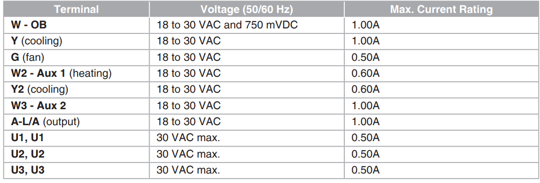
Electrical ratings
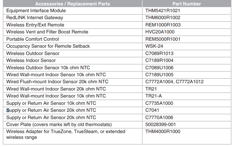
Accessories and replacement parts
In case of difficulty
Heating or cooling system does not respond
• Check circuit breaker and reset if necessary.
• Make sure power switch at heating & cooling system is on.
• Make sure furnace door is closed securely.
• Wait 5 minutes for the system to respond.
Screen displays “No Signal”
Thermostat has lost radio contact with the wireless network (usually because of a power outage). To restore power:
• Check circuit breaker and reset if necessary.
• Make sure power switch at heating & cooling system is on.
• Make sure furnace door is closed securely.
After power is restored, the thermostat will automatically restore wireless communication within a few minutes.
#1 Will this work with Mitsubishi split-type A/C units?
It will not work. Mitsubishi uses a thermistor on the indoor unit. That sense the air temperature
#2 Does this redlink thermostat communicate with smarthings like a z-wave device would?
It is wireless in the way that you don't have to run wires, but I see nothing in the instructions about connecting it to your cell phone or anything like that. I know there is an optional remote control you can purchase to go with it. Hope this helped
#3 Can i connect to home wifi or is there an app so i can control the thermostat when away from home? If not can i get something that will allow me to?
This is not a wifi enabled thermostat. The "wireless" aspect means that it does not have to be wired into your furnace.
 or
or  to set clock.
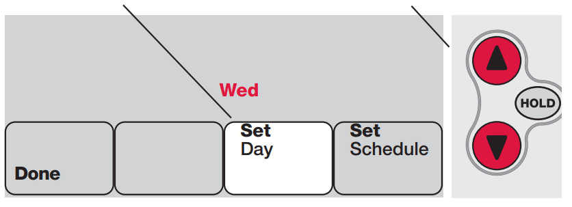
 or
or  to set your weekday Wake time (Mon-Fri), then press NEXT.
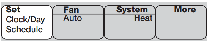
 Normally open, dry contacts
 Normally closed, dry contacts