USER MANUAL Programmable Thermostat
Package Includes
- T6 PRO Z-Wave Thermostat
- UWP™ Mounting System
- Honeywell Standard Installation Adapter (J-box adapter)
- Honeywell Decorative Cover Plate – Small; Size 4-49/64 in = 121mm.
- Screws and anchors
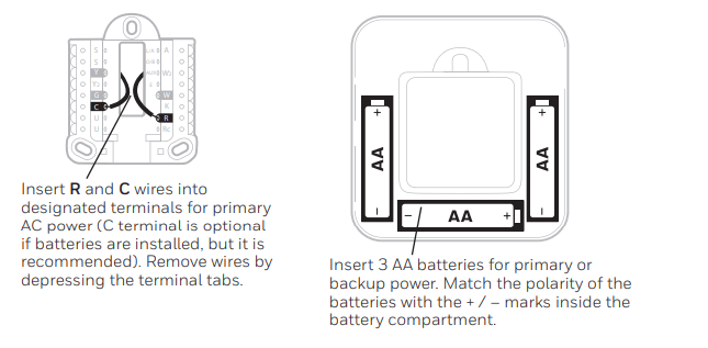
- 3 AA batteries
- Professional Install Guide
- Getting Started Guide
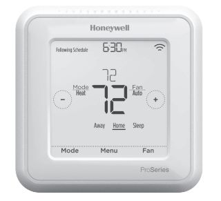
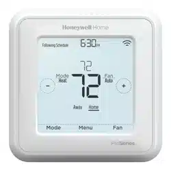
*TH6320ZW2003 depicted. Other models may vary. Actual size 4.09'' x 4.09'' x 1.06''
Compatibility
- Designed for battery operation (3 x AA batteries) or for 24 VAC power operation (via a “C” or common wire).
- Compatible with most single and multi-stage conventional and heat pump systems.
- Designed to work with any Z-Wave compliant controller or gateway; however, a security enabled Z-Wave Plus Controller is recommended to fully utilize all thermostat features.
- Works with millivolt systems.
- Does not work with electric baseboard heat (120-240V).
UWP Mounting System installation
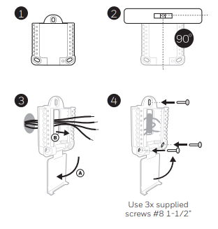
- Open package to find the UWP. See Figure 1.
- Position the UWP on the wall. Level and mark hole positions. See Figure 2. Drill holes at marked positions, and then lightly tap supplied wall anchors into wall using a hammer. ‒ Drill 7/32” holes for drywall.
- Pull the door open and insert wires through wiring hole of the UWP. See Figure 3.
- Place the UWP over the wall anchors. Insert and tighten mounting screws supplied with the UWP. Do not overtighten. Tighten until the UWP no longer moves. Close the door. See Figure 4.
Optional Decorative Cover Plate installation
Use the Optional Cover Plate when:
- Mounting the thermostat to an electrical junction box
- Or when you need to cover paint gap from the old thermostat.
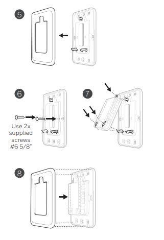
5. Separate the Junction Box Adapter from the Cover Plate. See Figure 5.
6. Mount the Junction Box Adapter to the wall or an electrical box using any of the eight screw holes. Insert and tighten mounting screws supplied with Cover Plate Kit. Do not overtighten. Make sure the Adapter Plate is level. See Figure 6.
7. Attach the UWP by hanging it on the top hook of the Junction Box Adapter and then snapping the bottom of the UWP in place. See Figure 7.
8. Snap the Cover Plate onto the Junction Box Adapter. See Figure 8.
Power options
NOTES:
- The T6 Pro Z-Wave thermostat works in battery mode or normal power mode based on its power source. The Z-Wave power mode can only be changed when the thermostat is NOT included in a Z-Wave network. You can check the power mode in the thermostat menu under MENU/DEVICE INFO.
- If a C wire is not used or present, the thermostat must be powered by batteries. The thermostat will operate in LSS mode (power-save, sleep mode) to help conserve battery life after it has been included in a Z-Wave network. The Z-Wave radio supports beaming. It allows other devices in the network to wake up the Z-Wave thermostat, accept commands, and then go back to sleep
- If you need the thermostat to operate in AOS mode (always listening mode) to act as signal repeater and to increase network reliability, you need to power the thermostat by 24 VAC. The AOS mode information is provided via Node Information Frame (NIF).
Wiring UWP
- Push down on the tabs to put the wires into the inner holes of their corresponding terminals on the UWP (one wire per terminal) until they are firmly in place. Gently tug on the wires to verify they are secure. If you need to release the wires again, push down the terminal tabs on the sides of the UWP.
Setting Slider Tabs
Set R Slider Tab.
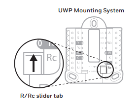
- Use built-in jumper (R Slider Tab) to differentiate between one or two transformer systems.
- If there is only one R wire, and it is connected to the R, Rc, or RH terminal, set the slider to the up position (1 wire).
- If there is one wire connected to the R terminal and one wire connected to the Rc terminal, set the slider to the down position (2 wires).
NOTE: Slider Tabs for U terminals should be left in place for other thermostat models.
Wiring terminal designations
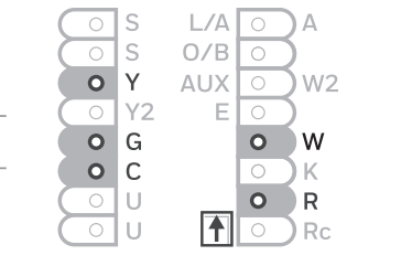
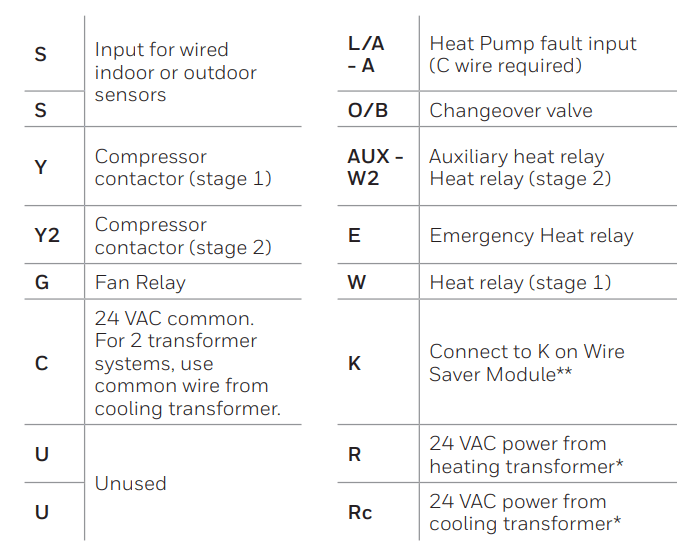
* Terminal can be jumped using Slider Tab. See “Setting Slider Tabs” above.
** The THP9045A1023 or THP9045A1098 Wire Saver Module can be used on heat/ cool systems when you only have four wires at the thermostat, and you need a fifth wire for a common wire. Use the K terminal in place of the Y and G terminals on conventional or heat pump systems to provide control of the fan and the compressor through a single wire—the unused wire then becomes your common wire. See THP9045 instructions for more information.
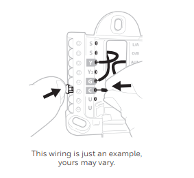
Note: Not all terminals may be used, depending on the system type that is being wired. The most commonly used terminals are shaded.
Wiring conventional systems: forced air and hydronics
1H/1C System (1 transformer)
- R Power [1]
- Rc [R+Rc joined by Slider Tab] [2]
- Y Compressor contactor
- C 24 VAC common [3]
- W Heat relay
- G Fan relay
Heat-only System
- R Power [1]
- Rc [R+Rc joined by Slider Tab] [2]
- C 24 VAC common [3]
- W Heat relay
Heat-only System (Series 20) [5]
- R Series 20 valve terminal “R” [1]
- Rc [R+Rc joined by Slider Tab] [2]
- Y Series 20 valve terminal “W”
- C 24 VAC common [3]
- W Series 20 valve terminal “B”
Heat-only System (power open zone valve) [5]
- R Power [1]
- Rc [R+Rc joined by Slider Tab] [2]
- W Valve
- C 24 VAC common [3]
1H/1C System (2 transformers)
- R Power (heating transformer) [1]
- Rc Power (cooling transformer) [1]
- Y Compressor contactor
- C 24 VAC common [3, 4]
- W Heat relay
- G Fan relay
Heat-only System with Fan
- R Power [1]
- Rc [R+Rc joined by Slider Tab] [2]
- C 24 VAC common [3]
- W Heat relay
- G Fan relay
Cool-only System
- R Power [1]
- Rc [R+Rc joined by Slider Tab] [2]
- Y Compressor contactor
- C 24 VAC common [3]
- G Fan relay
2H/2C System (1 transformer) [6]
- R Power [1]
- Rc [R+Rc joined by Slider Tab] [2]
- Y Compressor contactor (stage 1)
- C 24 VAC common [3]
- W Heat relay (stage 1)
- G Fan relay
- W2 Heat relay (stage 2)
- Y2 Compressor contactor (stage 2)
NOTES:
- Available wiring configurations may differ by product models/product numbers.
- Wire specifications: Use 18- to 22-gauge thermostat wire. Shielded cable is not required
[1] Power supply. Provide disconnect means and overload protection as required
[2] Move R-Slider Tab on UWP to the R setting. For more information, see "Setting Slider Tabs" on page 5.
[3] Optional 24 VAC common connection.
[4] If you do not have separate wires for the Aux and E terminals, connect the wire to the Aux terminal.
[5] In Installer Setup Options (ISU), set system type to Boiler. Set number of cool stages to 0. [6] In Installer Setup Options (ISU), set system type to Conventional. Set cool stages to 2, and set heat stages to 2
Wiring heat pump systems
1H/1C Heat Pump System
- R Power [1]
- Rc [R+Rc joined by Slider Tab] [2]
- Y Compressor contactor
- C 24 VAC common [3]
- O/B Changeover valve [7]
- G Fan relay
2H/1C Heat Pump System [8]
- R Power [1]
- Rc [R+Rc joined by Slider Tab] [2]
- Y Compressor contactor
- C 24 VAC common [3]
- O/B Changeover valve [7]
- G Fan relay
- Aux Auxiliary heat [4]
- E Emergency heat relay [4]
- L Heat pump fault input
2H/2C Heat Pump System [6]
- R Power [1]
- Rc [R+Rc joined by Slider Tab] [2]
- Y Compressor contactor (stage 1)
- C 24 VAC common [3]
- O/B Changeover valve [7]
- G Fan relay
- Y2 Compressor contactor (stage 2)
- L Heat pump fault input
3H/2C Heat Pump System [10]
- R Power [1]
- Rc [R+Rc joined by Slider Tab] [2]
- Y Compressor contactor (stage 1)
- C 24 VAC common [3]
- O/B Changeover valve [7]
- G Fan relay
- Aux Auxiliary heat [4]
- E Emergency heat relay [4]
- Y2 Compressor contactor (stage 2)
- L Heat pump fault input
Dual Fuel System
- R Power [1]
- Rc [R+Rc joined by Slider Tab] [2]
- Y Compressor contactor (stage 1)
- C 24 VAC common [3]
- O/B Changeover valve [7]
- G Fan relay
- Aux Auxiliary heat [4]
- E Emergency heat relay [4]
- Y2 Compressor contactor (stage 2 - if needed)
- L Heat pump fault input
- S Outdoor sensor
- S Outdoor sensor
NOTES:
- Do NOT use W for heat pump applications. Auxiliary heat must wire to AUX or E.
- Available wiring configurations may differ by product models/product numbers.
- Wire specifications: Use 18- to 22-gauge thermostat wire. Shielded cable is not required.
[1] Power supply. Provide disconnect means and overload protection as required.
[2] Move R-Slider Tab on UWP to the R setting. For more information, see "Setting Slider Tabs" on page 5.
[3] Optional 24 VAC common connection.
[4] If you do not have separate wires for the Aux and E terminals, connect the wire to the Aux terminal.
[6] In Installer Setup Options (ISU), set system type to Heat Pump. Set compressor stages to 2, and set Aux/E stages to 0.
[7] In Installer Setup Options (ISU), set Reversing Valve to O/B on Cool (for cool changeover) or to O/B on Heat (for heat changeover).
[8] In Installer Setup Options (ISU), set heat system type to Heat Pump. Set compressor stages to 1, and set Aux/E stages to 1.
[10] In Installer Setup Options (ISU), set system type to Heat Pump, set compressor stages to 2, and set Aux/E stages to 1.
Mounting thermostat
- Push excess wire back into the wall opening.
- Close the UWP door. It should remain closed without bulging.
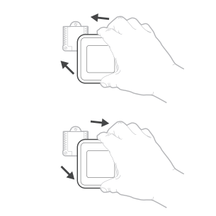
- Align the UWP with the thermostat, and push gently until the thermostat snaps in place.
- If needed, gently pull to remove the thermostat from the UWP.
- Turn the power on at the breaker box or switch.
Initial installer setup
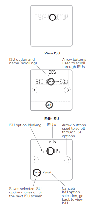
- After the T6 Pro Z-Wave thermostat has powered up, touch START SETUP on the thermostat.
- Touch
 or
or to toggle between Installer Set Up (ISU) options.
- Touch Edit or touch text area, and then touch or to edit default setup option.
- Touch Done or touch text area to confirm the setting or press Cancel
- Touch or to continue to setup another ISU option.
- To finish setup and save your settings, scroll to the Finish screen at the end of the ISU list.
Z-Wave setup
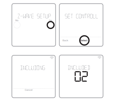
After you finish the installer setup and set the date and time, you will be asked to set up a Z-Wave to include the thermostat into Z-Wave network.
- Touch Yes to include the thermostat into Z-Wave network, or touch No if you want this to be done later. • You’ll be asked to set your primary controller to INCLUDE MODE. Please refer to the user manual of your Z-Wave controller.
- After inclusion procedure has been initiated on your Z-Wave controller, touch Select on the thermostat.
- If the inclusion procedure is successful, INCLUDED, the node ID, and the Z-Wave connected status icon appear on the screen. If the procedure fails, FAILED TO INCLUDE appears on the screen. If this happens, position the thermostat closer to the Z-Wave controller and repeat the inclusion procedure.
- Your controller will indicate whether the thermostat was successfully added to its network. (Please refer to the user manual of your Z-Wave controller.)
NOTES:
- This thermostat will function as a normal programmable thermostat with the default program schedule if not included in a Z-Wave network. Once you include the thermostat into Z-Wave network, it assumes to be programmed from your Z-Wave controller and the program schedule on the thermostat is turned OFF by default. For more information, see "Scheduling options" on page 12.
- To include or exclude the thermostat from Z-Wave network after initial thermostat setup, go to thermostat MENU/Z-WAVE SETUP.
- Before adding the thermostat to a Z-Wave network, check that it does not already belong to one. If the thermostat is included in Z-Wave network, it offers an option to exclude. If the thermostat is excluded from Z-Wave network, it offers an option to include. You can also check the status by viewing the Node ID located in the thermostat MENU/DEVICE INFO. An excluded thermostat should show zero for the Node ID (000).
- Whether you are including or excluding the thermostat from Z-Wave network, first you have to initiate it on your Z-Wave controller. Please refer to the user manual of your Z-wave controller.
- For other specific tasks such as adding the thermostat to home automation scenes or groups, refer to the user manual of your Z-Wave controller.
Advanced Z-Wave temperature reporting
This thermostat may be configured to report the actual room temperature in a higher resolution than can be shown on the thermostat display. The default temperature reporting resolution is 1 °F or 0.5 °C. When configured to ADVANCED, the temperature reporting resolution will be 0.5 °F or 0.25 °C. To change default temperature reporting to a higher resolution, go to thermostat MENU/Z-WAVE SETUP/TEMP REPORT and set to ADVANCED. The temperature is reported by every displayed value change, and no later than 2 hours from last report.
NOTE: When higher temperature resolution reporting set, you may experience different resolution of temperature displayed on the thermostat and Z-Wave controller.
Z-Wave connection status
Z-Wave connection status is located in the upper-right corner of the screen.
 Thermostat is included and connected to a Z-Wave network.
 Thermostat is excluded from a Z-Wave network.
 Thermostat is either included in a Z-Wave network but the Z-Wave signal is lost, or is included but AC power is lost (battery used as backup). In this case, Z-Wave radio is turned off to preserve battery life. AC power must be restored or you have to change the power mode. It can be done via excluding thermostat from Z-wave network and including again in battery power mode where batteries are used as main power source. You can check the actual power mode in the thermostat MENU/DEVICE INFO.
System operation setting
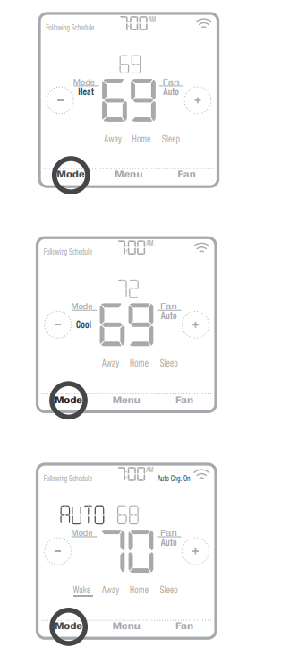
- Press the Mode button to cycle to the next available System mode.
- Cycle through the modes until the required System mode is displayed and leave it to activate.
System modes:
- Heat: Controls the heating system.
- Cool: Controls the cooling system.
- Off: Turns the heating and cooling systems off.
- Auto: When enabled, the thermostat will automatically use heating or cooling to reach the desired temperature.
- Em Heat: Controls auxiliary or emergency heat; only available on systems with a heat pump.
NOTES:
- Em Heat and Auto modes may not appear on the thermostat screen, depending on your equipment and how the thermostat was configured.
- Em Heat is only available if the thermostat is configured to control a heat pump and an auxiliary/ emergency heat stage.
- When Auto mode is enabled and initiated, Auto Chg. On will appear in the upper-right corner of the thermostat home screen, and the active mode (Heat or Cool) will be displayed. Auto mode is disabled by default. To enable it, see "Installer setup – advanced menu"
Fan operation setting
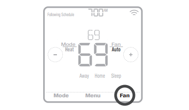
- Press the Fan button to cycle to the next available Fan mode.
- Cycle through the modes until the required Fan mode is displayed and leave it to activate.
NOTE: Available Fan modes vary with system settings.
Fan modes:
- On: The fan will run continuously.
- Auto: The fan will run only when the heating or cooling system is on.
- Circ: The fan will run at random intervals at least 35% of the time to keep air circulating throughout your home.
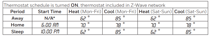
Scheduling options
This thermostat may be configured to be programmable or non programmable. Thermostat schedule is an optional menu item. It will only show up in the thermostat menu if enabled in the Installer setup – advanced menu. It provides setting for local thermostat schedule control.
Once the thermostat is included in to Z-Wave network, it assumes to be programmed from your Z-Wave controller and the program schedule on the thermostat is turned OFF by default. Use just the controller or associated app to program schedule (automation scenes) for the thermostat.
- Only Home and Away periods appear on the thermostat home screen.
- Home temperature setpoints are adjustable on the thermostat Home screen. Common for all days.
- Away mode is an Energy saving mode adjustable in the thermostat MENU/ AWAY SETTING. Common for all days.
See table below with default, adjustable settings:
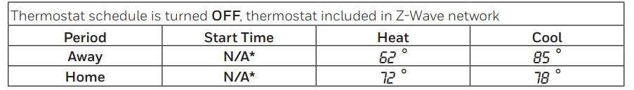
*Triggered by Z-Wave controller
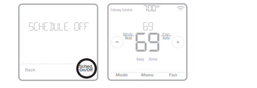
Enabling thermostat schedule when thermostat is included in Z-Wave network (optional):
Z-Wave controllers from various manufacturers may or may not support the Z-Wave Thermostat General V2 Device class used by the Honeywell T6 pro Z-Wave Thermostat. If your controller does not support full thermostat device class functions, it may still be able to control basic Home/ Away (Energy Saving) modes of the thermostat through BASIC_SET commands (ON/OFF) used by the controller for other Z-Wave devices (eg. lighting devices). When only basic commands capable to receive from controller, you can enable the local thermostat schedule to differentiate between temperatures when you are away and when you are at home to differentiate between home and sleep temperatures.
- Home, Away and Sleep periods appear on the thermostat home screen.
- Home and Sleep temperature and time settings are adjustable in the thermostat MENU/SCHEDULE.
- Away mode is an Energy saving mode adjustable in the thermostat MENU/ AWAY SETTING. Common for all days.
See table below with default 5+2 schedule (Mon-Fri; Sat-Sun), adjustable settings:
*Triggered by Z-Wave controller
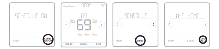
- If the Schedule menu on the thermostat does not appear, make sure that thermostat schedule is enabled. This setting is accessed from INSTALLER SETUP – ADVANCED MENU (see pages 14, 15), ISU 120 - Schedule type. Here you can also choose from pre-defined different thermostat program schedule types to be adjustable in the thermostat MENU/SCHEDULE.
Program schedule on the thermostat when not included in Z-Wave network (not operated by Z-Wave controller):
The Honeywell T6 Pro Z-Wave thermostat will function as fully programmable thermostat when not operated by your controller. Each day can be programmed for different heating and cooling setpoints in 4 unique periods (Wake, Away, Home, Sleep) in the thermostat MENU/SCHEDULE. Make sure that thermostat schedule is enabled in INSTALLER SETUP – ADVANCED (see pages 14, 15), ISU 120 - Schedule type.
See table below with default 5+2 schedule (Mon-Fri; Sat-Sun), adjustable settings:
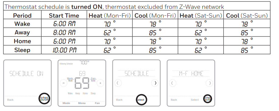
- Wake, Away, Home, Sleep periods appear on the thermostat home screen.
- Temperature setpoints for all four periods, different per day or group of days are adjustable in thermostat MENU/ SCHEDULE.
Key features
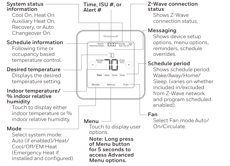
- The screen will wake up by pressing the center area of the displayed temperature. If powered by 24 VAC, the screen stays lit for 45 seconds after you complete changes
- If powered by battery only, the screen stays lit for 8 seconds.
- Brightness of an inactive backlight can be adjusted in the thermostat MENU only if the thermostat is powered by 24 VAC
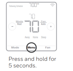
To access the advanced menu, press and hold the Menu button for 5 seconds. Touch or to go through the options in the advanced menu.
Advanced menu options
Device Setup
- This is used to access the device ISU setting.
Screen Lock
- The thermostat touch screen can be locked fully or partially
System Test
- Test the heating and cooling system.
Reset
- Access all reset options on the thermostat. This is the only place to access factory reset.
Range Stop (Temperature)
- Set the Minimum Cool and Maximum Heat temperature set points.
Table 1.
Note: ISU options available may vary upon the thermostat model and equipment setup.
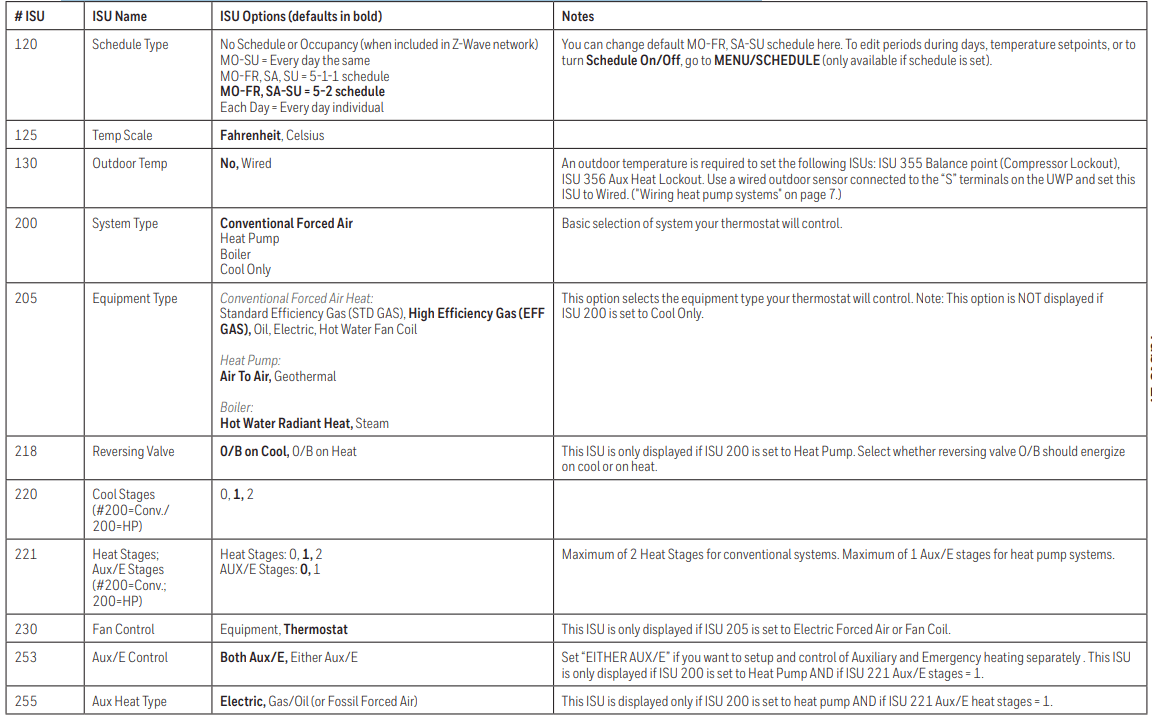
Table 2.
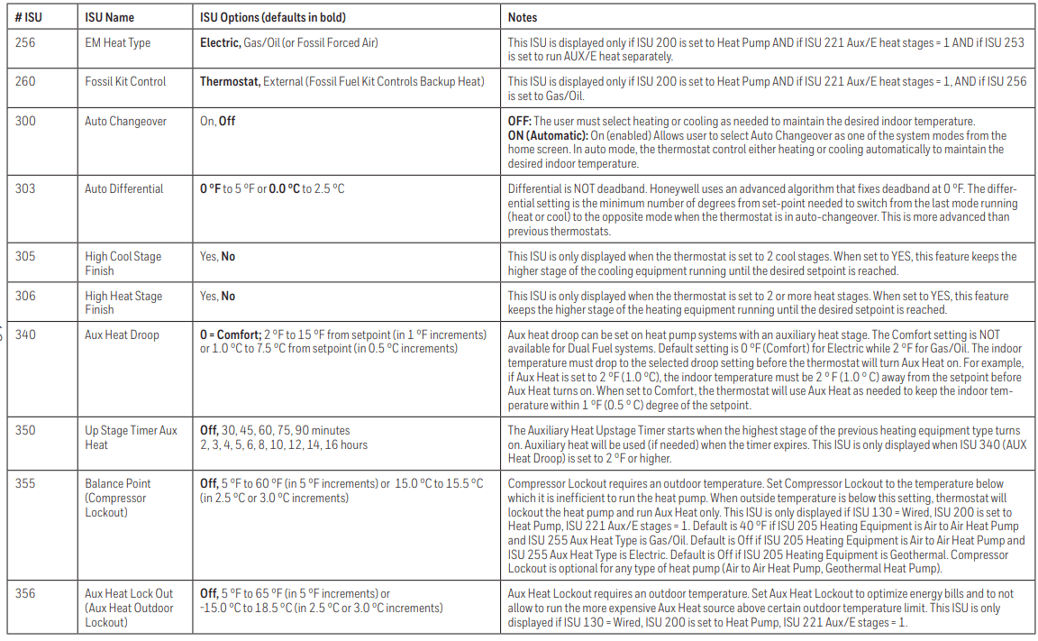
Table 3.
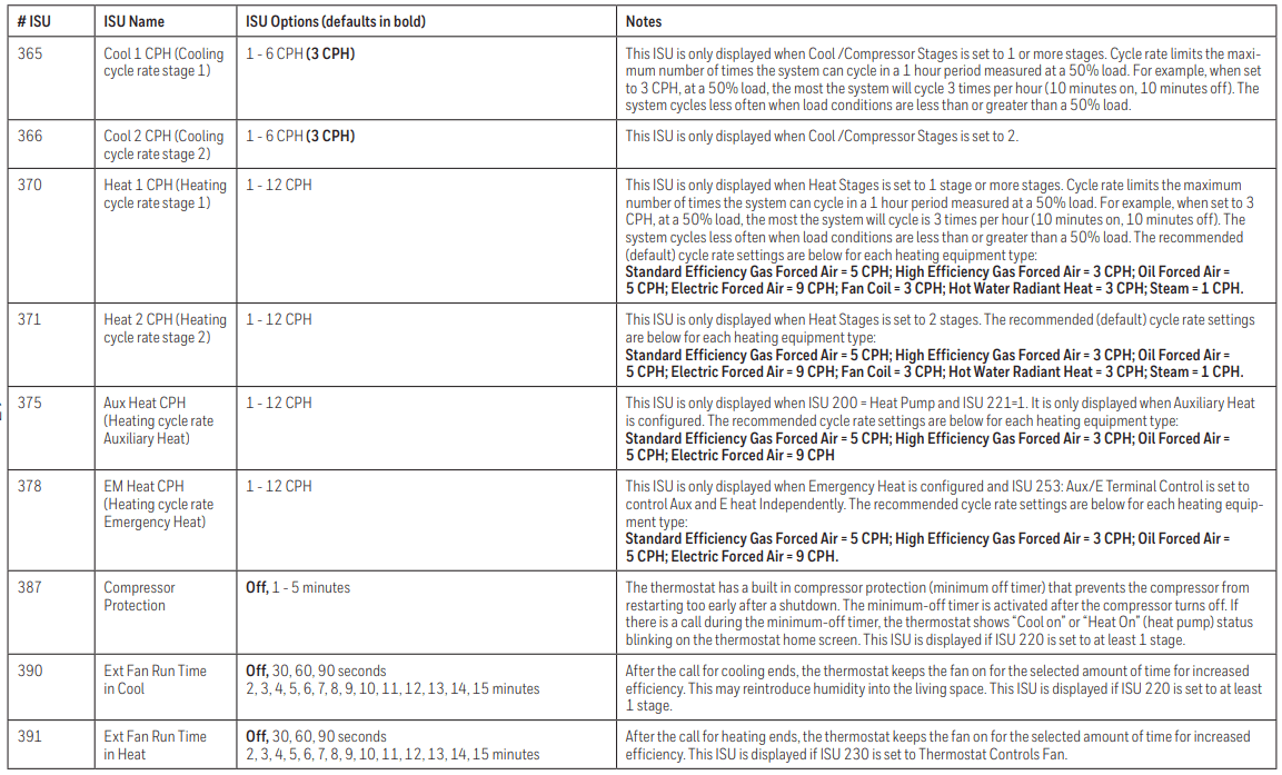
Table 4.
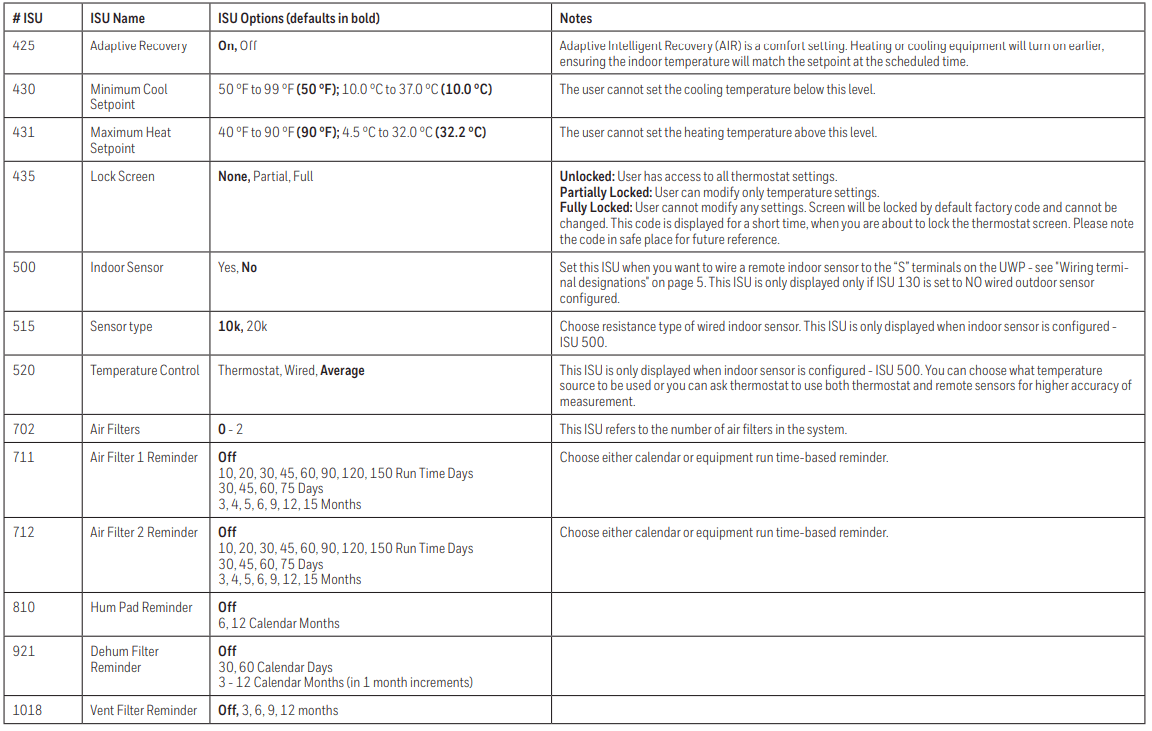
Table 5.
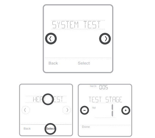
You can test the system setup in ADVANCED MENU under SYSTEM TEST option.
- Press and hold Menu on the thermostat for 5 seconds to access ADVANCED MENU options.
- Touch or to go to SYSTEM TEST.
- Touch Select or touch text area.
- Touch or to select system test type. Touch Select or touch text area.
- For the heat test and cool test, use
 or
or to activate each stage of the equipment. For the fan test, use or to turn the fan on and off.
NOTE: The clock is used as a timer while the stages are running. The Heat On and Cool On indicators are displayed when the system test is running.
Viewing equipment status
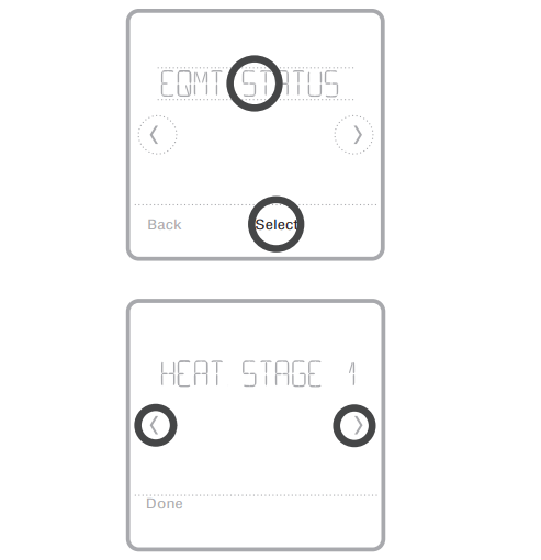
You can see the status of thermostatcontrolled equipment in the Menu under the EQMT STATUS option.
- Touch Menu on your thermostat.
- Touch or to go to EQMT STATUS. Touch Select or touch text area.
- Touch or to view statuses of all the equipment the thermostat is controlling. Depending on what feature the thermostat supports or how it was installed, the Equipment Status screen reports data for the following systems:
Alerts and reminders
Alerts and reminders are displayed via the alert symbol and alert number in the clock area on the home screen. You can read more information about active alerts, snooze or dismiss non-critical alerts in Menu/Alerts.
54
- Thermostat Humidity Sensor Error
- The sensor of the thermostat has encountered an error. Please contact dealer to replace the thermostat.
164
- Heat Pump Needs Service
- Heat pump needs service. Contact dealer to diagnose and service heat pump.
170
- Internal Memory Error
- The memory of the thermostat has encountered an error. Please contact dealer for assistance.
171
- Set the Date and Time
- Set the date and time on your thermostat. The date and time are required for certain features to operate, like the program schedule.
173
- Thermostat Temperature Sensor Error
- The sensor of the thermostat has encountered an error. Please contact dealer to replace the thermostat.
177
- Indoor Temperature Sensor Error
- Wired indoor temperature sensor is not connected or there is a wiring short. Please contact dealer for assistance.
178
- Outdoor Temperature Sensor Error
- Wired outdoor temperature sensor is not connected or there is a wiring short. Please contact dealer for assistance
181
- Replace Air Filter (1)
- Replace air filter (1). Reset the timer by touching the "dismiss" button on thermostat screen after it is replaced.
182
- Replace Air Filter (2)
- Replace air filter (2). Reset the timer by touching the "dismiss" button on thermostat screen after it is replaced.
184
- Replace Humidifier Pad
- Replace humidifier pad. Reset the timer by touching the “dismiss” button on the thermostat screen after it is replaced.
185
- Replace Dehumidifier Filter
- Replace the dehumidifier filter. Reset the timer by touching "dismiss" button on thermostat screen after it is replaced
187
- Clean or Replace Ventilator Filter
- Clean or replace ventilator filter. Reset the timer by touching the “dismiss” button on thermostat screen after it is replaced.
188
- Replace UV Bulb (1)
- Replace UV Bulb (1). Reset the timer by touching the "dismiss" button on thermostat screen after it is replaced.
189
- Replace UV Bulb (2)
- Replace UV Bulb (2). Reset the timer by touching the "dismiss" button on thermostat screen after it is replaced.
252
- AC Power Lost
- If batteries used as backup power it would drain batteries quickly so Z-Wave communication needs to be turned off. The working power mode can only be changed when thermostat is NOT included in a Z-Wave network. Either to exclude and include thermostat back in to Z-Wave network to change the power mode to LSS (power-save, sleep mode) or to resume AC power. You can check the actual power mode in the thermostat MENU/DEVICE INFO.
405
- Battery Low
- Battery low. Please turn the system mode to off and replace the batteries.
407
- Battery Critical
- Battery critical. Thermostat cannot control your system. Please replace the batteries immediately
546
- Z-Wave Not Configured
- Z-Wave has a not been configured yet to receive commands from your Z-Wave network. Please follow steps on how to include thermostat in to Z-Wave network.
547
- Z-Wave Radio Error
- Z-Wave module is not operating. Thermostat cannot receive commands from your Z-Wave network. Please contact dealer to replace the thermostat.
Troubleshooting
Screen is blank
- Check circuit breaker and reset if necessary.
- Make sure power switch at heating and cooling system is on.
- Make sure furnace door is closed securely.
- If battery powered, make sure the batteries are correctly inserted and are not dead.
Screen is difficult to read
- Change screen brightness in thermostat Menu. Increase brightness intensity for inactive backlight of the thermostat screen (max. is level 5). Setting is available only if thermostat is AC powered.
Heating or cooling system does not respond
- Touch Mode to set system to Heat. Make sure the temperature is set higher than the Inside temperature.
- Touch Mode to set system to Cool. Make sure the temperature is set lower than the Inside temperature.
- Check circuit breaker and reset if necessary.
- Make sure power switch at heating & cooling system is on.
- Make sure furnace door is closed securely.
Heat runs with cooling
- Verify there is not a wire attached to W for heat pump systems. See wiring
Specifications
Model Number: TH6320ZW2003
Model Name: T6 Pro Z-Wave Thermostat
Model Description: Programmable Z-Wave thermostat with touchscreen
Stages:
- Up to 3 Heat / 2 Cool Heat Pump
- Up to 2 Heat / 2 Cool Conventional
Power Requirements Battery power:
- AA alkaline battery 3pcs.
- C-wire input: 18-30VAC; 50Hz-60Hz
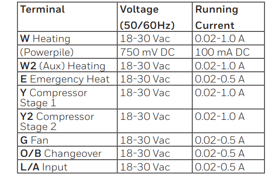
Electrical Ratings:
Dimension: 4.09” x 4.09” x 1.06”
Display Size: 6.55 sq. in.
Temperature Ranges
- Adjustable Heat Temperature Range Setting: 40-90 °F (4.5-32.0 °C)
- Adjustable Cool Temperature Range Setting: 50-99 °F (10.0-37.0 °C)
Operating Ambient Temperature Range
- Thermostat: 37-102°F (2.78-38.89 °C)
Operating Relative Humidity Range
- Thermostat: 5% to 90% (non-condensing)
Temperature Sensor Accuracy
- Thermostat: ± 1.5 °F at 70 °F (0.85 °C at 21.0 °C)
Physical Dimensions in Inches (mm) (H x W x D)
- T6 PRO Z-Wave Thermostat (TH6320ZW2003): 4-5/64 x 4-5/64 x 1-1/16 (104 x 104 x 27)
- UWP Mounting System (included): 2-9/32 x 2-13/64 x 2-43/64 (58 x 56 x 10)
- Standard Installation Adapter (included): 3-29/32 x 3-57/64 x 21/32 (99 x 99 x 17)
- Decorative Cover Plate – Small (included): 4-49/64 x 4-49/64 x 11/32 (121 x 121 x 9)
- Decorative Cover Plate – Large (THP2400A1068): 6-7/64 x 6-7/64 x 9/32 (155 x 155 x 7)
Z-Wave Radio
- Frequency (USA and Canada): 908.42 MHz
- Certified: Z-Wave Plus
- Generic Device Type: Thermostat
- Node type (C-wire): Always On Slave (AOS)
- Node type (Battery): Listening Sleeping Slave (LSS)
- Z-Wave Chipset: ZM5202AU
Supported Z-Wave Command Classes:
- Z-Wave Plus Info V2
- Supervision V1
- Transport Service V2
- Association V2
- Version V2
- Association Group Information V2
- Basic V1
- Battery V1
- Clock V1
- Configuration V4
- Device Reset Local V1
- Manufacturer Specific V2
- Sensor Multilevel V5
- Notification V3
- Powerlevel V1
- Security 2 V1
- Thermostat Fan Mode V3
- Thermostat Fan State V1
- Thermostat Mode V3
- Thermostat Operating State V1
- Thermostat Setpoint V2
NOTES:
Thermostat Mode V3:
- Some of the reported modes are manufacturer specific if not covered by the Z-Wave command class.
Basic V1 (basic set command implementation):
- Value 0x00 Device goes to Energy saving setting (AWAY mode)
- Values 0x01-0x63 and 0xFF Device goes to Comfort setting (HOME mode)
Notification V3:
- Notification V3 is enabled by default (Power management alarm handling). Notification Type: Power Management (0x08). Notification Events: AC mains disconnected (0x02), AC mains re-connected (0x03).
Security:
- All supported Z-Wave Command classes are supported securely (S2 unauthenticated), except Transport Service V2, Security 2 V1 and Z-Wave Plus Info V2
Association V2:
- Group ID: 1; Maximum Nodes: 1; Description: Z-Wave Plus Lifeline
- Command Classes reported: Multilevel Sensor, Thermostat Setpoint, Thermostat Mode
- Thermostat Fan Mode, Thermostat Operating State, Thermostat Fan State, Basic