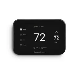
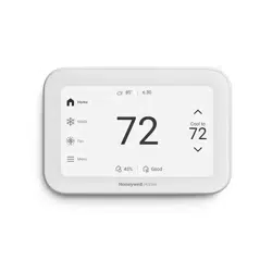
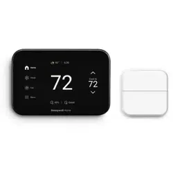
User manual Thermostat
UWP Mounting System installation
1. Open package to find the UWP.
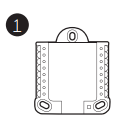
2. Position the UWP on the wall. Level and mark hole positions. Drill holes at marked positions, and then lightly tap supplied wall anchors into wall using a hammer.
If your box contains red anchors, drill 7/32” (5.6 mm) holes for drywall. If your box contains yellow anchors, drill 3/16” (4.8 mm) holes for drywall.

3. Pull the door open and insert wires through wiring hole of the UWP.
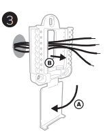
4. Place the UWP over the wall anchors. Insert and tighten mounting screws supplied with the UWP. Do not overtighten. Tighten until the UWP no longer moves. Close the door.

Use 3x supplied screws (#8 1-1/2" [38 mm] for red anchors and #6 1-1/2 [38 mm] for yellow anchors)
Optional Decorative Cover Plate installation
Use the Optional Cover Plate when you need to cover paint gap from the old thermostat.
There are different cover plates depending on when the thermostat was manufactured. One plate is square, the other is rectangular.
1. Separate the cover plate from the mounting plate.

2. Mount the mounting plate to the wall using any of the screw holes. Insert and tighten mounting screws supplied with the cover plate. Do not overtighten. Make sure the mounting plate is level. See Figure 2a (square) or 2b (rectangle).

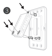
3. Attach the UWP by hanging it on the top hook of the mounting plate and then snapping the bottom of the UWP in place.
4. Snap the Cover Plate onto the mounting plate.
If there are no existing wall anchors, you can follow the same instructions for the UWP Mounting System installation to install the cover plate. Just use 2 screws rather than 3.
Wiring UWP
Push down on the tabs to put the wires into the inner holes of their corresponding terminals on the UWP (one wire per terminal) until they are firmly in place. Gently tug on the wires to verify they are secure. If you need to release the wires again, push down the terminal tabs on the sides of the UWP.

Terminal designations

* The THP9045A1098 C-wire adaptor is used on heat/cool systems when you only have four wires at the thermostat and you need a fifth wire for a common wire. Use the K terminal in place of the Y and G terminals on conventional or heat pump systems to provide control of the fan and the compressor through a single wire—the unused wire then becomes your common wire. See THP9045 instructions for more information.
** Ventilation is not available on all models. When the U slider is in the down position (2 wires), the U contacts are a dry set of contacts. If your ventilation system requires 24 volts, move the U slider to the up position (1 wire). Lower U terminal is internally jumped to the Rc terminal. In this application, you would hook up one wire from your damper to the upper U terminal and the other to the common side of the transformer.
Setting Slider Tabs
Set R Slider Tab, see Figure 9.

- Use built-in jumper (R Slider Tab) to differentiate between one or two transformer systems.
- If there is only one R wire, and it is connected to the R, Rc, or RH terminal on the old thermostat, set the slider to the up position (1 wire).
- If there is one wire connected to the R terminal and one wire connected to the Rc terminal, set the slider to the down position (2 wires).
Set U Slider Tab, see Figure 10.
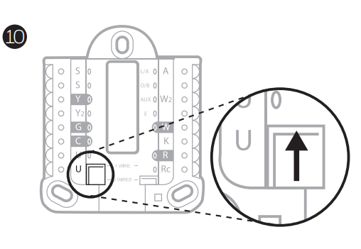
- Use built-in jumper (U Slider Tab) of relay to wire ventilation. Please note that ventilation is not supported on all models.
- When the U Slider Tab is in the down position (2 wires) the U contacts are a dry set of contacts.
- If the ventilator is powered by the cooling transformer, move the jumper switch to the up position (1 wire). With this switch set to 1 wire, the lower U terminal is internally jumped to the Rc terminal. In this application, hook up one wire from the vent damper to the U terminal and the other to the common side of the cooling system transformer.
Wiring
NOTES:
- Available wiring configurations differ by product models/product numbers.
- Use 18- to 22- gauge thermostat wire. Shielded cable is not required.
- Set the R Slider Tab on the UWP to the up position (1 wire) for 1 transformer systems or the down position (2 wires) for 2 transformer systems. See "Setting Slider Tabs".
- Set the U Slider Tab to the up position (1 wire) for non-powered ventilation or the down position (2 wires) for powered ventilation. See "Setting Slider Tabs".
Ventilation systems
NOTE: Ventilation is not available on all models.
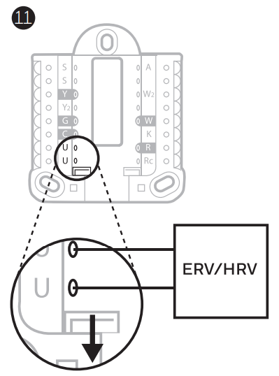
Using U Slider Tab
- Wired to ERV/HRV whole house ventilator with internal power supply
- Wired to fresh air damper powered by furnace transformer.

Mounting thermostat
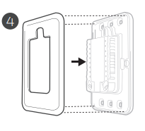
- Push excess wire back into the wall opening.
- Close the UWP door. It should remain closed without bulging.
- Align the UWP with the thermostat, and push gently until the thermostat snaps in place.
- If needed, gently pull to remove the thermostat from the UWP.
- Search for local rebates: Your thermostat may now be eligible for local rebates. Search for offers in your area at HoneywellHome.com/Rebates

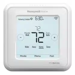
Installer setup – using the thermostat
Setup using the thermostat
- After the thermostat has powered up, touch START SETUP on the thermostat. You’ll be asked if you want to perform setup via app. Touch No.

- Touch
 or
or  to toggle between Installer Set Up (ISU) options.
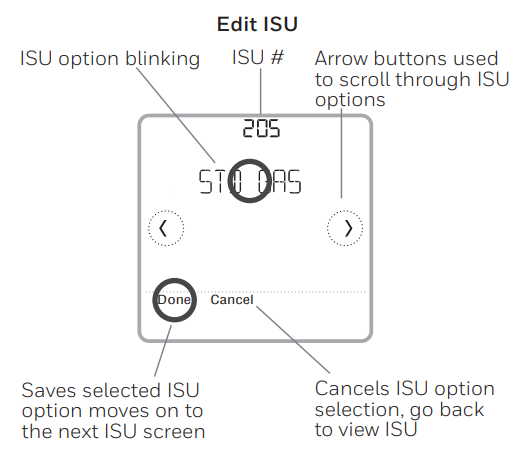
- Touch Edit or touch text area, and then touch or to edit default setup option.
- Touch Done or touch text area to confirm the setting or press Cancel.
- Touch or to continue to setup another ISU option.
NOTES:
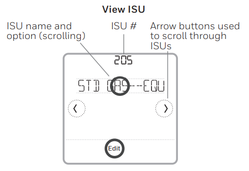
- To see a list of all setup parameters, go to "Installer setup options (ISU) – advanced menu". The thermostat displays the ISU name and the ISU number.
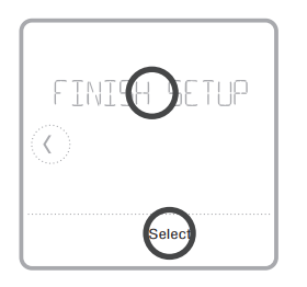
- To finish setup and save your settings, scroll to the Finish screen at the end of the ISU list.
- Touch Select or touch text area to save changes and exit, or touch to return to initial setup screen.
Installer setup – using the Honeywell Home app
Setup using the app
Download the Honeywell Home app from App Store or Google Play to use a hidden PRO installation feature that will allow you to configure the thermostat and personally invite your customer to connect to the installed thermostat at the same time.

Enter Contractor Mode
To enter Contractor Mode, press and hold the Honeywell Home logo for 5 seconds. Then tap Confirm to begin using Contractor Mode. Follow steps to personally invite your customer to connect their Honeywell Home App.

To access the advanced menu, press and hold the Menu button for 5 seconds. Touch or to go through the options in the advanced menu.

Advanced menu options
- Device Setup: This is used to access the device ISU setting.
- Screen Lock: The thermostat touch screen can be set to lock fully or partially.
- Rater View: A read only place to view all the ventilation settings.
- System Test: Test the heating and cooling system.
- Range Stop (Temperature): Set the minimum, maximum, cool and heat temperature set points.
- Reset: Access all reset options on the thermostat. This is the only place to access factory reset.
Key features
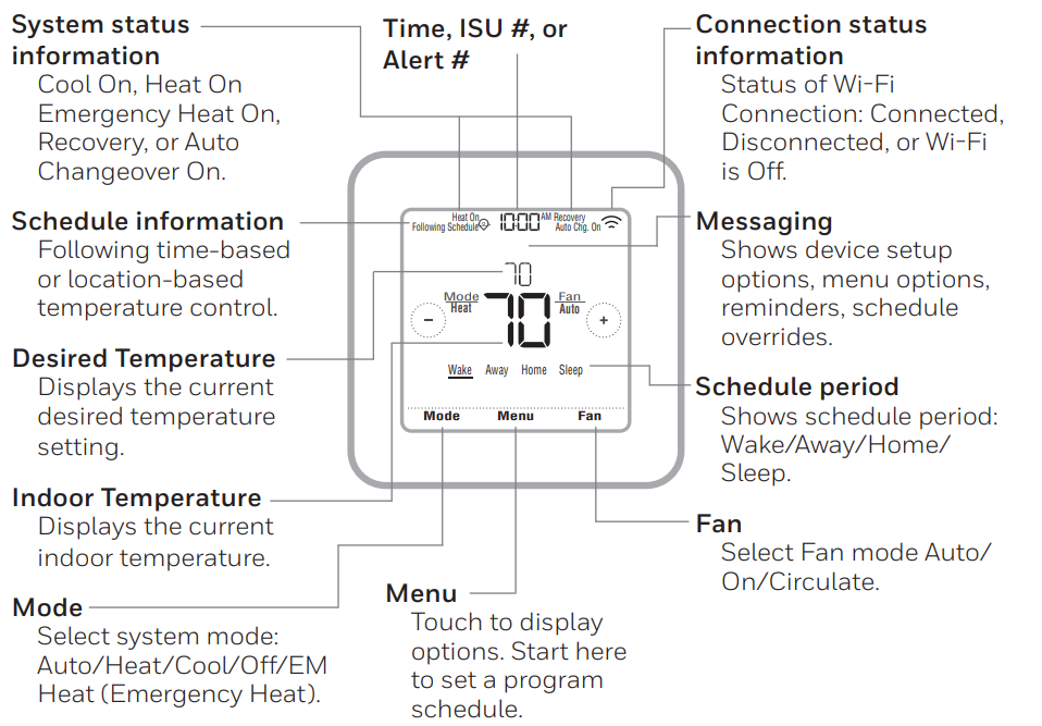
Note: Long press of Menu button for 5 seconds to access Advanced Menu options.
The screen will wake up by pressing the center area of the displayed temperature.
The screen will stay lit for 45 seconds. Brightness can be adjusted in the Menu.
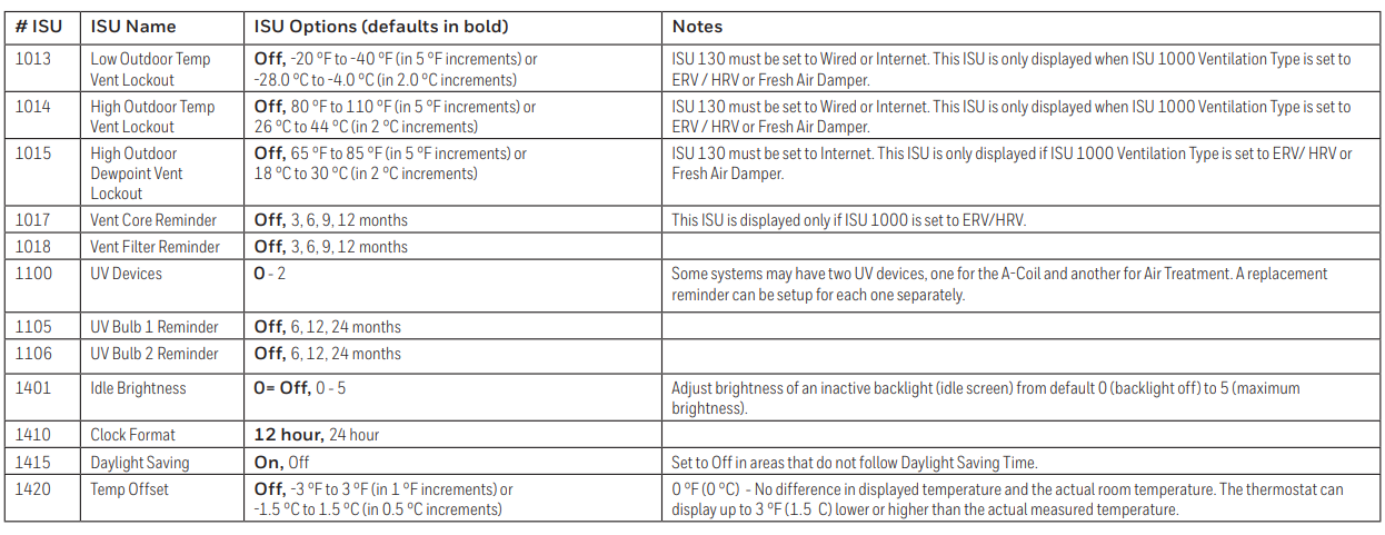
Note: ISU options available may vary upon the thermostat model and equipment setup.
Table 1.

Table 2.
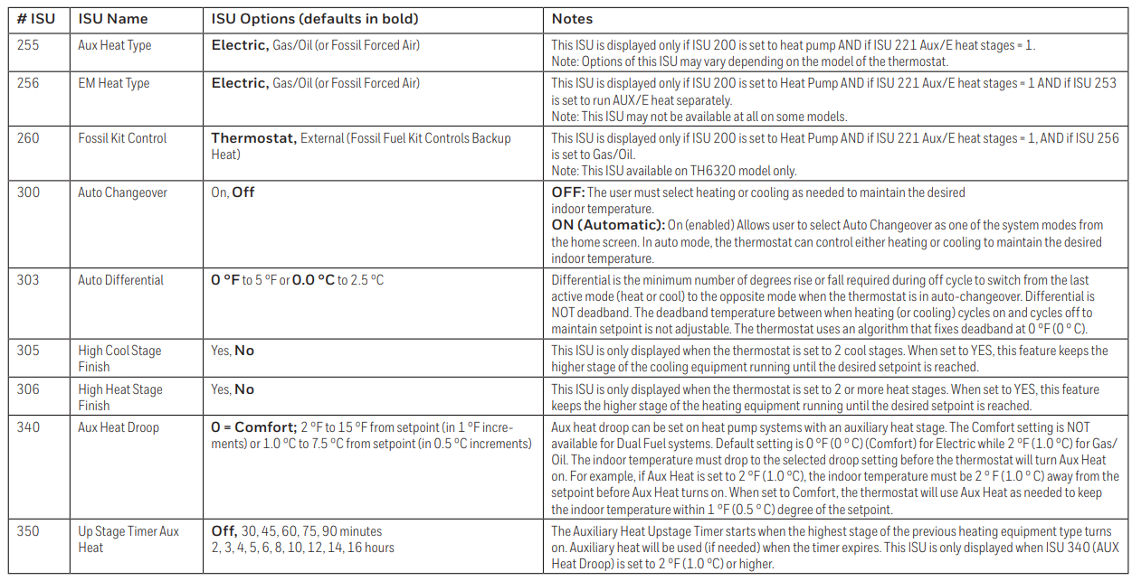
Table 3.

Table 4.

Table 5.

Table 6.
You can test the system setup in ADVANCED MENU under SYSTEM TEST option.
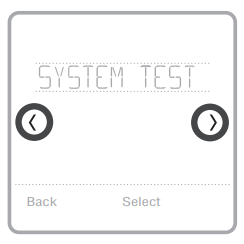
- Press and hold Menu on the thermostat for 5 seconds to access ADVANCED MENU options.
- Touch or to go to SYSTEM TEST.
- Touch Select or touch text area.
- Touch or to select system test type. Touch Select or touch text area.
- For the heat test and cool test, use (+) or (-) to activate each stage of the equipment. For the fan test, use or to turn the fan on and off.
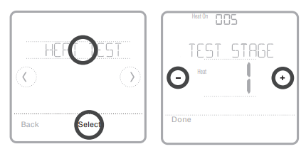
NOTE: The clock is used as a timer while the stages are running. The Heat On and Cool On indicators are displayed when the system test is running.
Viewing equipment status
You can see the status of thermostatcontrolled equipment in the Menu under the EQMT STATUS option.

- Touch Menu on your thermostat.
- Touch or to go to EQMT STATUS. Touch Select or touch text area.
- Touch or to view statuses of all the equipment the thermostat is controlling. Depending on what feature the thermostat supports or how it was installed, the Equipment Status screen reports data for the following systems:
- Heating and cooling
- Fan
- Ventilation (available on certain models only)
Troubleshooting
Screen is blank
- Check circuit breaker and reset if necessary.
- Make sure power switch at heating and cooling system is on.
- Make sure furnace door is closed securely
Screen is difficult to read
- Change screen brightness in thermostat Menu. Increase brightness intensity for inactive backlight of the thermostat screen (max. is level 5).
Heating or cooling system does not respond
- Touch Mode to set system to Heat. Make sure the temperature is set higher than the Inside temperature.
- Touch Mode to set system to Cool. Make sure the temperature is set lower than the Inside temperature.
- Check circuit breaker and reset if necessary.
- Make sure power switch at heating & cooling system is on.
- Make sure furnace door is closed securely.
Heat runs with cooling
- Verify there is not a wire attached to W for heat pump systems.
Alerts and reminders
Alerts and reminders are displayed via the alert symbol and alert number in the clock area on the home screen. You can read more information about active alerts, snooze or dismiss non-critical alerts in Menu/Alerts.
Number 164: Heat Pump Needs Service
- Heat pump needs service. Contact dealer to diagnose and service heat pump.
Number 168: Wi-Fi Radio Error
- Wireless features are not available. Try removing the thermostat from the wallplate or power cycle at breaker for 1 minute. If the code is still shown, please contact dealer to replace the thermostat.
Number 170: Internal Memory Error
- The memory of the thermostat has encountered an error. Please contact dealer for assistance.
Number 171: Set the Date and Time
- Set the date and time on your thermostat. The date and time are required for certain features to operate, like the program schedule.
Number 173: Thermostat Temperature Sensor Error
- The sensor of the thermostat has encountered an error. Please contact dealer to replace the Thermostat.
Number 175: AC Power Resumed
- AC power resumed to thermostat after power loss.
Number 177: Indoor Temperature Sensor Error
- Wired indoor temperature sensor is not connected or there is a wiring short. Please contact dealer for assistance.
Number 178: Outdoor Temperature Sensor Error
- Wired outdoor temperature sensor is not connected or there is a wiring short. Please contact dealer for assistance.
Number 181: Replace Air Filter (1)
- Replace air filter (1). Reset the timer by touching the "dismiss" button on thermostat screen after it is replaced.
Number 182: Replace Air Filter (2)
- Replace air filter (2). Reset the timer by touching the "dismiss" button on thermostat screen after it is replaced.
Number 183: Clean Humidifier Tank and Replace Water Filter
- Clean humidifier tank and replace the water filter, or contact dealer to do this for you. Reset the timer by touching the “dismiss” button on the thermostat screen after it is replaced. 184 Replace Humidifier Pad Replace humidifier pad. Reset the timer by touching the “dismiss” button on the thermostat screen after it is replaced.
Number 185: Replace Dehumidifier Filter
- Replace the dehumidifier filter. Reset the timer by touching "dismiss" button on thermostat screen after it is replaced.
Number 186: Clean Ventilator Core
- Clean ventilator core. Reset the timer by touching the “dismiss” button on thermostat screen after it is replaced.
Number 187: Clean or Replace Ventilator Filter
- Clean or replace ventilator filter. Reset the timer by touching the “dismiss” button on thermostat screen after it is replaced.
Number 188: Replace UV Bulb (1)
- Replace UV Bulb (1). Reset the timer by touching the "dismiss" button on thermostat screen after it is replaced.
Number 189: Replace UV Bulb (2)
- Replace UV Bulb (2). Reset the timer by touching the "dismiss" button on thermostat screen after it is replaced.
Number 210: Register Online For Outdoor Temperature
- Online registration is required to receive outdoor temperature from the Internet. Outdoor temperature is needed for your current system setup. Download the Honeywell Home app to register your thermostat.
Number 388: Register Online for Remote Access and Outdoor Temperature
- Online registration is required for remote access and outdoor temperature. Download the Honeywell Home app to register your thermostat.
Number 399: No Internet
- The connection to the Internet has been lost. Please check your network settings.
Number 400: No Wi-Fi Signal
- The Wi-Fi signal has been lost. Please wait for the thermostat to reconnect or select a new Wi-Fi network. Follow steps in the Honeywell Home app
Number 508: Wi-Fi Not Configured
- Please download the Honeywell Home app and follow the steps to connect thermostat to your Wi-Fi network.
CAUTION: ELECTRICAL HAZARD
Can cause electrical shock or equipment damage. Disconnect power before beginning installation.
CAUTION: EQUIPMENT DAMAGE HAZARD
Compressor protection is bypassed during testing. To prevent equipment damage, avoid cycling the compressor
quickly.
CAUTION: MERCURY NOTICE
If this product is replacing a control that contains mercury in a sealed tube, do not place the old control in the trash. Contact your local waste management authority for instructions regarding recycling and proper disposal.
Specifications
Temperature Ranges
- Heat: 40 °F to 90 °F (4.5 °C to 32.0 °C)
- Cool: 50 °F to 99 °F (10.0 °C to 37.0 °C)
Operating Ambient Temperature
- 37 °F to 102 °F (2.8 °C to 38.9 °C)
Shipping Temperature
- -20 °F to 120 °F (-28.9 °C to 48.9 °C)
Operating Relative Humidity
- 5% to 90% (non-condensing)
Physical Dimensions in inches (mm) (H x W x D)
- T6 Pro Smart Thermostat (TH6320WF2003): 4-5/64 x 4-5/64 x 1-1/16 (104 x 104 x 27)
- T6 Pro Smart Thermostat (TH6220WF2006): 4-5/64 x 4-5/64 x 1-1/16 (104 x 104 x 27)
Electrical Ratings

Power Consumption
- Backlight On: 1.48VA
- Backlight Off: 0.88VA
5-year limited warranty
For Warranty information go to http://customer.resideo.com
FCC REGULATIONS
47 CFR § 15.19 (a)(3)
This device complies with part 15 of the FCC Rules. Operation is subject to the following two conditions:
- This device may not cause harmful interference, and
- This device must accept any interference received, including interference that may cause undesired operation
47 CFR § 15.21 (USA only)
- Changes or modifications not expressly approved by the party responsible for compliance could void the user’s authority to operate the equipment.
47 CFR § 15.105 (b)
- See https://customer.resideo.com/en-US/support/residential/codesand-standards/FCC15105/Pages/default.aspx for additional FCC information for this product.
IC REGULATIONS
RSS-GEN
This device contains licence-exempt transmitter(s)/receiver(s) that comply with Innovation, Science and Economic Development Canada’s licence-exempt RSS(s). Operation is subject to the following two conditions:
- This device may not cause interference.
- This device must accept any interference, including interference that may cause undesired operation of the device.
The operation of this equipment is subject to the following two conditions: (1) this equipment or device may not cause harmful interference, and (2) this equipment or device must accept any interference, including interference that may cause undesired operation.