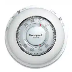
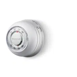
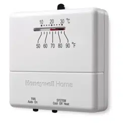
User manual Thermostat
Pre-installation checklist
Check package contents:
- Thermostat
- Wall anchors & screws (2 each)
- Large Print Subbase Switch Labels
- Coverplate
Before you begin, make sure you have:
- No. 2 Phillips & small pocket screwdrivers
- Hammer
- Level (optional)
- Pencil
- Drill and bit (3/16” for drywall, 7/32” for plaster)
Product application
This thermostat provides electronic control of 24 VAC single-stage heating and cooling systems.
System Types
- Gas, oil, or electric heat with air conditioning
- Warm air, hot water, high-efficiency furnaces, heat pumps, steam, gravity
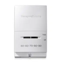
- Heat only
- Heat only with fan
- Cool only
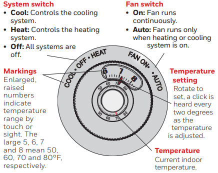
System Settings
Fan Settings
Specifications
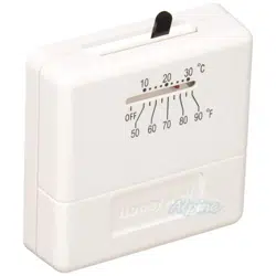
Temperature Range
- 40° to 90°F (4.5° to 32°C)
Shipping Temperature
- -20° to 120°F (-28.9° to 48.9°C)
Operating Relative Humidity
- 5% to 90% (non-condensing)
Electrical Ratings
- Voltage: 20–30 VAC
- Running current: 0.02–1.0 A, 50/60 Hz
Installation tips
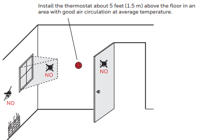
Do not install in locations where the thermostat can be affected by:
- Drafts or dead spots behind doors and in corners
- Hot or cold air from ducts
- Sunlight or radiant heat from appliances
- Concealed pipes or chimneys
- Unheated/uncooled areas such as an outside wall behind the thermostat
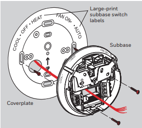
Subbase and base installation
1. Pull wires through wire hole. Position coverplate on wall, level and mark hole positions.
2. Drill holes (3/16” for drywall, 7/32” for plaster) and tap in supplied wall anchors.
3. Pull wire through coverplate and subbase, position over anchors, then insert and tighten mounting screws. Check level if desired.
4. Apply the large-print labels to the coverplate, matching the labels on the subbase.
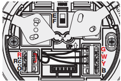
Wiring
1. Loosen screw terminals, insert wires into terminal block, then re-tighten screws.
2. Push excess wire back into the wall opening.
3. Plug the wall opening with nonflammable insulation to prevent drafts from affecting thermostat operation.
Terminal Designations
W Heat relay.
Y Compressor contactor.
G Fan relay.
O Heat pump changeover valve energized in cooling.
Rc Cooling power. Connect to secondary side of cooling system transformer.
R Heating power. Connect to secondary side of heating system transformer.
B Heat pump changeover valve energized in heating.
NOTES
R & Rc terminals
In single-transformer system, leave metal jumper in place between R & Rc. Remove metal jumper if two-transformer system.
Heat pump systems
If wiring to a heat pump, use a small piece of wire (not supplied) to connect terminals W and Y.
Wire specifications
Use 18- to 22-gauge thermostat wire.
Shielded cable is not required.
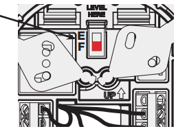
Fan operation settings
Fan operation settings:
F: For gas or oil heating systems, leave the fan operation switch in this factory-set position (for systems that control the fan in a call for heat).
E: Change the switch to this setting for heat pump or electric heat systems. (This setting is for systems that allow the thermostat to control the fan in a call for heat, if a fan wire is connected to the G terminal.)
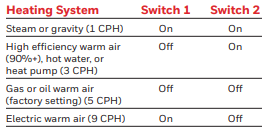
Cycle rate settings
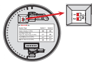
Move the cycle rate switches to the proper setting for your system (see table below).
Thermostat mounting
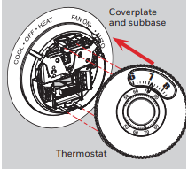
Align the slots on the base with tabs on the thermostat, then push gently until the thermostat snaps into place.
Operation
CAUTION: EQUIPMENT DAMAGE HAZARD
Do not operate cooling system when outdoor temperature is below 50°F (10°C).