User Guide Non-Programmable Thermostat
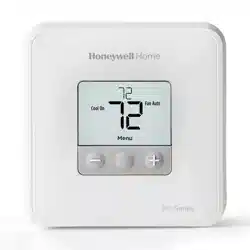
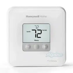
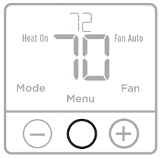
Thermostat controls
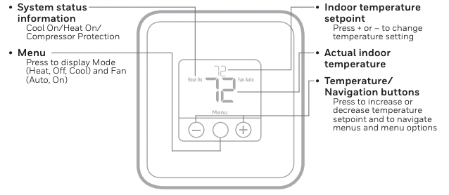
The screen will wake up by pressing any of the three buttons. If powered by the C wire, the screen stays lit for 45 seconds after you complete changes. If powered by battery only, the screen stays lit for 8 seconds. Depending on how your thermostat was installed, the screen light may always be on.
System operation settings
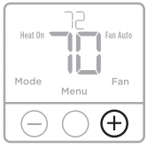
1 Press the Menu to cause the Mode and Fan menus to appear.
2 Press Mode  to cycle through the available modes.

NOTE: Available System modes vary by model and system settings.
System modes:
‒ Heat
‒ Cool
‒ Off
Fan operation settings
1 Press Menu to cause the Mode and Fan menus to appear.
2 Press Fan  to cycle through Fan modes.
NOTE: Available Fan modes vary with system settings.
Fan modes:
‒ Auto: Fan runs only when the heating or cooling system is on.
‒ On: Fan is always on.
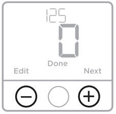
Setting degrees Fahrenheit (F) or Celcius (C)
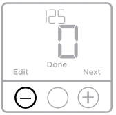
1 Press and hold Menu (center) for approximately 3 seconds to enter advanced menu.
2 Change setup option 125 by pressing Edit to change the value: 0 = Fahrenheit, 1 = Celsius.
3 Press Done to Save and return to the main menu screen.
Built-in compressor protection
Damage can occur if the compressor is restarted too soon after shutdown. This feature forces the compressor to wait for a few minutes before restarting.
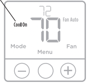
During the wait time, the display will flash the message Cool On (or Heat On if you have a heat pump). When the safe wait time has elapsed, the message stops flashing and the compressor turns on.
Message flashes until safe restart time has elapsed.
Battery replacement
Batteries are optional (to provide backup power) if your thermostat was wired to run on AC power when installed. If your thermostat was not wired to run on AC power, then batteries are required.
Install fresh batteries immediately when the low battery icon appears. The icon appears about two months before the batteries are depleted.
Even if the low battery icon does not appear, you should replace batteries once a year, or before leaving home for more than a month.
NOTE: When replacing batteries, alkaline batteries are recommended.

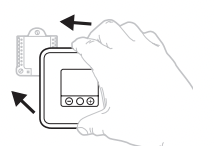
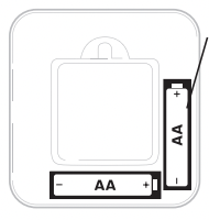
When the low battery warning appears, press gently to loosen the thermostat and then carefully pull it from the wall mount.
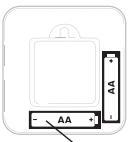
Insert fresh alkaline AA batteries and reinstall thermostat.
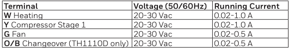
Electrical Ratings
Troubleshooting
If you have difficulty with your thermostat, please try the following suggestions. Most problems can be corrected quickly and easily
Display is blank
- Check circuit breaker and reset if necessary.
- Make sure power switch for heating & cooling system is on.
- Make sure furnace door is closed securely.
- Make sure fresh AA alkaline batteries are correctly installed (see above)
Heating or cooling system does not respond
- Press Mode button to set system Heat (see page 2). Make sure the desired temperature is set higher than the inside temperature.
- Press Mode button to set system Cool (see page 2). Make sure the desired temperature is set lower than the inside temperature.
- Check circuit breaker and reset if necessary.
- Make sure power switch for heating & cooling system is on.
- Make sure furnace door is closed securely.
- Wait 5 minutes for the system to respond.
Temperature settings do not change
- If you are in the correct mode, but you cannot set the heat from 32 °F to 90 °F (0 °C to 32 °C), or set the cool from 50 °F to 99 °F (10 °C to 37 °C), you may have range-stops restricting your setting. Check with the installer to see if they set range-stops.
“Cool On” or “Heat On” is flashing
- Compressor protection feature is engaged. Wait 5 minutes for the system to restart safely, without damage to the compressor (see page 2).
Installation Instructions
Optional Cover Plate installation
NOTE: If Optional Cover Plate is not required, see “UWP Mounting System installation” on next page. Use the Optional Cover Plate when you need to cover paint gap from old thermostat. There are different cover plates depending on when the thermostat was manufactured.
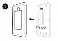
For the square cover plate:
1. Separate the Cover Plate from Mounting Plate.
2. Mount the Mounting Plate on to the wall using any of the 8 screw holes. Insert and tighten mounting screws supplied with Cover Plate Kit. Do not overtighten. See Figure 2. Make sure the Mounting Plate is level.
3. Attach the UWP by hanging it on the top hook of the Mounting Plate and then snapping the bottom of the UWP in place. See Figure 3.
4. Snap the Cover Plate onto the Mounting Plate. See Figure 4.
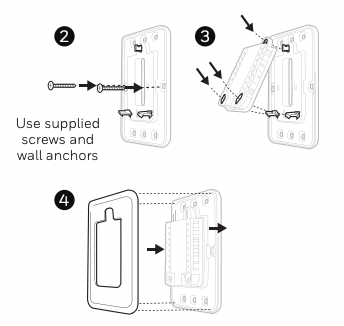
For the rectangular cover plate:
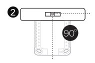
1. Mount the Cover Plate on the wall using any of the 6 screw holes. Insert and tighten the mounting screws supplied with the Cover Plate. Do not overtighten. See Figure 1. Make sure the Cover Plate is level. Attach the UWP by hanging it on the top hook of the Cover Plate and then snapping the bottom of the UWP in place. See Figure 2.
2. If there are no existing wall anchors:
- a. Position the Cover Plate on wall. Level and mark hole positions. See Figure 1.
- b. Drill holes at marked positions, and then lightly tap supplied wall anchors into the wall using a hammer.
•If your box contains red anchors, drill 7/32” (5.6 mm) holes.
•If your box contains yellow anchors, drill 3/16” (4.8 mm) holes. •Use 2x supplied screws (#8 1-1/2” (38 mm) for red anchors and #6 1-1/2” (38 mm) for yellow anchors).
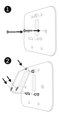
UWP Mounting System installation
1. Before starting, turn the power off at the breaker box or switch. Open package to find the UWP. See Figure 1.
2. Position the UWP on wall. Level and mark hole positions. See Figure 2. Drill holes at marked positions, and then lightly tap supplied wall anchors into the wall using a hammer.
‒ If your box contains red anchors, drill 7/32” holes.
‒ If your box contains yellow anchors, drill 3/16” holes.
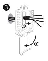
3. Pull the door open and insert the wires through wiring hole of the UWP. See Figure 3.
4. Place the UWP over the wall anchors. Insert and tighten mounting screws supplied with the UWP. Do not overtighten. Tighten until the UWP no longer moves. Close the door. See Figure 4.

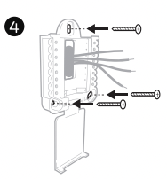
Use 3x supplied screws (#8 1-1/2 for red anchors and #6 1-1/2 for yellow anchors)
Power options
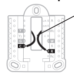
Insert R and C wires into designated terminals for primary AC power (C terminal is optional if batteries are installed, but it is recommended). Remove wires by depressing the terminal tabs.
Insert AA batteries for primary or backup power.
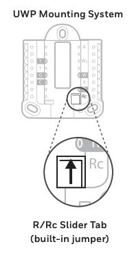
Setting Slider Tabs
Set R Slider Tab.
- Use built-in jumper (R Slider Tab) to differentiate between one or two transformer systems.
- If there is only one R wire, and it is connected to the R, Rc, or RH terminal, set the slider to the up position (1 wire).
- If there is one wire connected to the R terminal and one wire connected to the Rc terminal, set the slider to the down position wires).
NOTE: Slider Tabs for U terminals should be left in place for T1 Pro models.
UWP Wiring terminal designations
- Y Compressor contactor (stage 1)
- Y2 Not used for T1 thermostat.
- G Fan Relay
- C 24VAC common. For 2 transformer systems, use common wire from cooling transformer.
- L/A - A Not used for T1 thermostat.
- O/B Changeover Valve (TH1110D only)
- AUX - W2 Not used for T1 thermostat.
- E Not used for T1 thermostat.
- W Heat relay (stage 1)
- K Not used for T1 thermostat.
- R 24VAC power from heating transformer*
- Rc 24VAC power from cooling transformer*
* Terminal can be jumped using Slider Tab. See “Setting Slider Tabs” above.
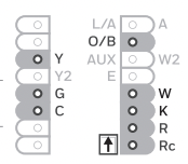
Note: Not all terminals may be used, depending on the system type that is being wired. The most commonly used terminals are shaded.
Thermostat mounting
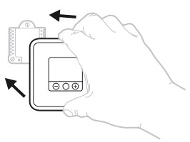
1. Push excess wire back into the wall opening.
2. Close the UWP door. It should remain closed without bulging.
3. Align the UWP with the thermostat, and push gently until the thermostat snaps in place.
4. Turn the power on at the breaker box or switch.
Installer setup (ISU)
1 Press and hold Menu (center) for approximately 3 seconds to enter menu.
2 Press Edit to change values within a setup option.
3 Press Next to advance to the next setup option.
4 Press Done to Save and return to the main menu screen.
NOTE: To keep the factory default settings, press to advance through the setup options. Once you pass the last option, the thermostat will automatically save and return you to the main menu.
NOTE: A complete list of all setup (ISU) parameters and options starts below and continues through page 7.
Installer setup options (ISU)
NOTE: Depending on system settings, not all options may be available
125 Temperature Indication
- Scale 0 = Fahrenheit
- 1 = Celsius
200 Heating System Type
- 1 = Conventional Forced Air Heat
- 2 = Heat Pump (TH1110D only)
- 3 = Radiant Heat
- 5 = None (Cool Only)
Note: This option selects the basic system type your thermostat will control.
205 Heating Equipment Type
Conventional Forced Air Heat:
- 1 = Standard Efficiency Gas Forced Air
- 2 = High Efficiency Gas Forced Air
- 3 = Oil Forced Air
- 4 = Electric Forced Air
- 5 = Hot Water Fan Coil
Heat Pump:
- 7 = Air to Air Heat Pump
- 8 = Geothermal Heat Pump
Radiant Heat:
- 9 = Hot Water Radiant Heat
- 12 = Steam
Note: This option selects the equipment type your thermostat will control.
Note: This feature is NOT displayed if feature 200 is set to Cool Only
218 Reversing Valve O/B
- 0 = O (O/B in Cool)
- 1 = B (O/B in Heat)
Note: This option is only displayed if the Heat Pump configured. Select whether reversing valve O/B should energize in cool or in heat.
220 Cool Stages / Compressor Stages 200=Conv / 200=HP
Note: Select how many Cool or Compressor stages of your equipment the thermostat will control. Set value to 0 if you do not have Cool Stage/ Compressor Stage. This ISU will not be shown on TH1010D model.
221 Heat Stages
Note: Select how many Heat stages of your equipment the thermostat will control. This ISU will not be shown on TH1010D model.
230 Fan Control in Heat
- 1 = Equipment Controls Fan
- 2 = Thermostat Controls Fan
Note: This ISU is only displayed if ISU 205 is set to Electric Forced Air or Fan Coil.
430 Minimum Cool Setpoint
- 50 °F to 99 °F (50 °F)
- 10.0 °C to 37.0 °C (10.0 °C)
Note: The cool temperature cannot be set below this level. This ISU will not be shown on TH1010D model unless ISU 200 is set to 5 (cool only).
431 Maximum Heat Setpoint
- 32 °F to 90 °F (90 °F)
- 0 °C to 32.0 °C (32 °C)
Note: The heat temperature cannot be set above this level. This ISU will not be shown on TH1010D model unless ISU 200 is not set to 5 (cool only).
1400 Backlighting
- 0 = On Demand
- 1 = Continuous
Note: Common wire needed for continuous. This ISU will not be shown if the device is powered only by battery.
1420 Temperature Display Offset
- -3 to 3F (0)
- -1.5 to 1.5C (0)
Note: 0 °F - No difference in displayed temperature and the actual room temperature. The thermostat can display up to 3 °F (1.5 C) lower or higher than the actual measured temperature.