Installation Guide Digital Thermostat
Installation
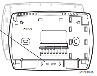
Wallplate installation
Remove the wallplate from the thermostat by pulling from the bottom, then follow directions below for mounting.
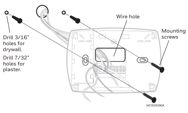
1. Pull wires through wire hole.
2. Position wallplate on wall, level and mark hole positions with pencil.
3. Drill holes at marked positions as shown below, then tap in supplied wall anchors.
4. Place wallplate over anchors, insert and tighten mounting screws.
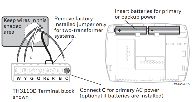
Power options
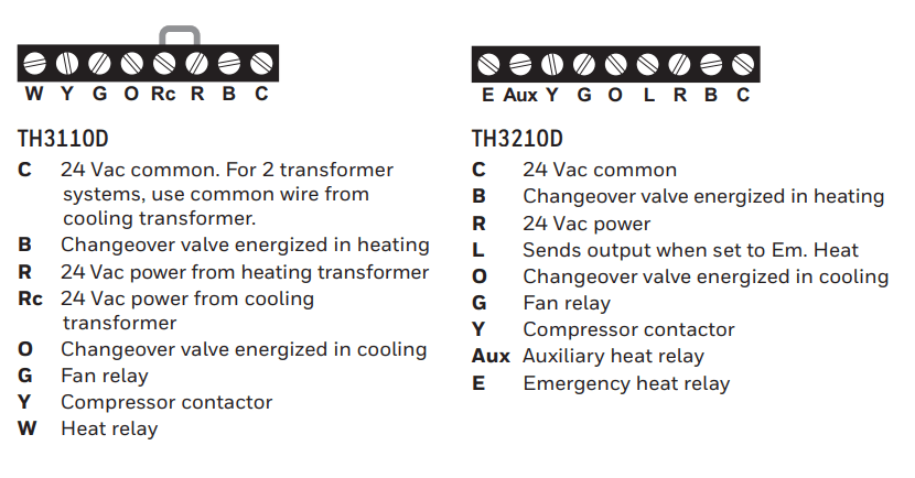
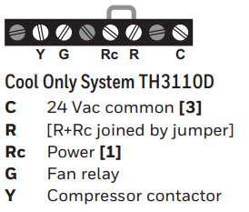
Wiring terminal designations
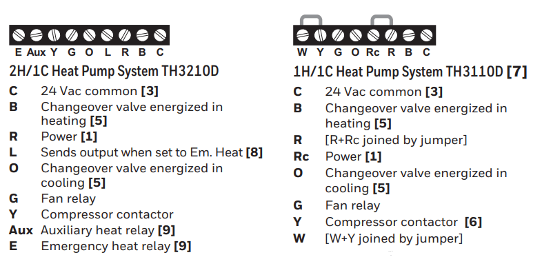
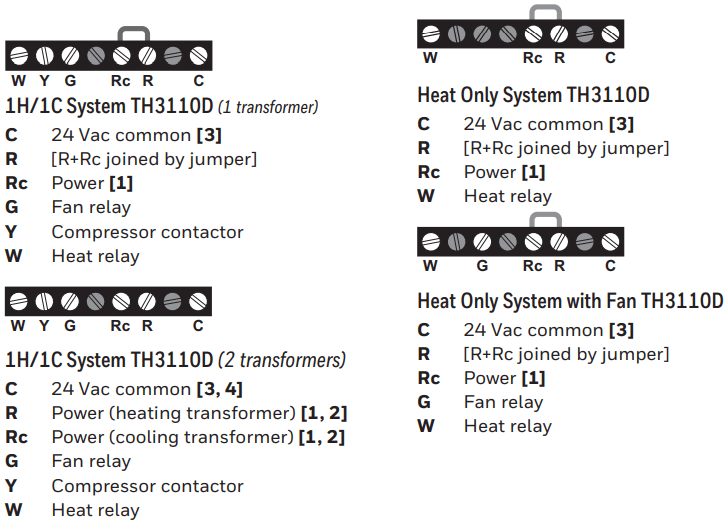
Wiring conventional and heat pump systems
NOTES
Wire specifications: Use 18- to 22-gauge thermostat wire. Shielded cable is not required.
[1] Power supply. Provide disconnect means and overload protection as required.
[2] Remove jumper for 2-transformer systems.
[3] Optional 24 Vac common connection.
[4] Common connection must come from cooling transformer.
[5] Use either O or B terminals for changeover valve.
[6] Use a small piece of wire (not supplied) to connect W and Y terminals.
[7] Set fan operation switch to Heat Pump (see page 5) and configure system type for heat pump (see page 6).
[8] L terminal sends a continuous output when thermostat is set to Em. Heat. Connect to Honeywell Home zoning panels to switch the panel to Emergency Heat.
[9] Install field jumper between Aux and E if there is no emergency heat relay.
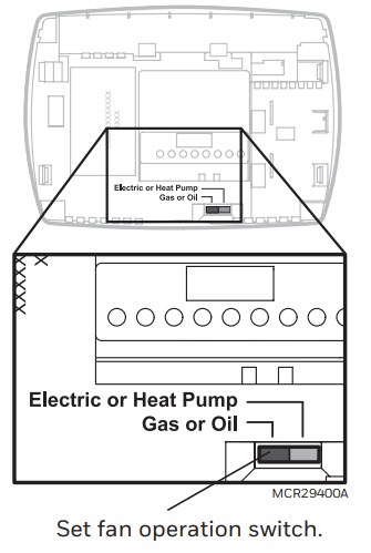
Fan operation settings (TH3110D only)
Gas or Oil: For gas or oil heating systems, leave the fan operation switch in this factory-set position. (This setting is for systems that control the fan in a call for heat.)
Electric or Heat Pump: Change the switch to this setting for heat pump or electric heat systems. (This setting is for systems that allow the thermostat to control the fan in a call for heat, if a fan wire is connected to the G terminal.)
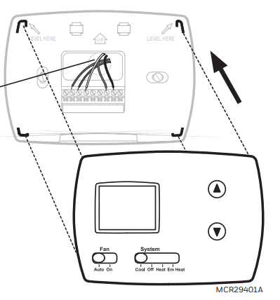
Thermostat mounting
1. Align the 4 tabs on the wallplate with corresponding slots on the back of the thermostat.
2. Push gently until the thermostat snaps in place.
3. Push excess wire back into the wall opening.
4. Plug wall opening with nonflammable insulation.
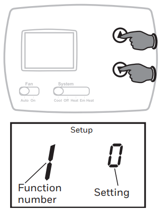
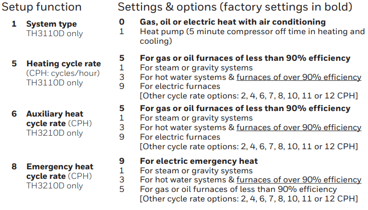
Installer Setup
Follow the procedure below to configure the thermostat to match the installed heating/cooling system, and customize feature operation as desired.
To begin, press and hold the  and
and  buttons until the display changes.
- Press to change settings.
- Press to advance to next function.
- Press and hold to exit and save settings.
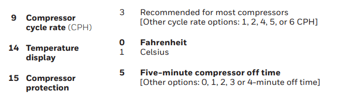
Compressor Protection (Setup Function 15): Forces the compressor to wait a few minutes before restarting, to prevent damage. During the wait time, the message Cool On or Heat On (heat pumps only) will flash on the display.
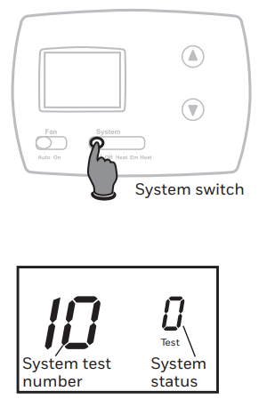
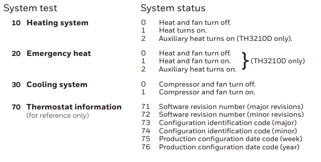
Installer system test
1. Set SYSTEM switch to Heat.
2. Press to turn on and check systems (see table, below).
3. Press until systems turn off.
4. Set SYSTEM switch to Em Heat and repeat steps 2-3 above (TH3210D only).
5. Set SYSTEM switch to Cool and repeat steps 2-3 above.
6. Press and hold to terminate test at any time.
Troubleshooting
If you have difficulty with your thermostat, please try the following suggestions. Most problems can be corrected quickly and easily.
| Display is blank |
•Check circuit breaker and reset if necessary.
•Make sure power switch at heating & cooling system is on.
•Make sure furnace door is closed securely.
•Make sure fresh AA alkaline batteries are correctly installed (see page 2). |
| Heating or cooling system does not respond |
•Set system switch to Heat. Make sure the temperature is set higher than the Inside temperature.
•Set system switch to Cool. Make sure the temperature is set lower than the Inside temperature.
•Wait 5 minutes for the system to respond. |
| Temperature settings do not change |
Make sure heating and cooling temperatures are set to
acceptable ranges:
•Heat: 40° to 90°F (4.5° to 32°C).
•Cool: 50° to 99°F (10° to 37°C). |
| “Cool On” or “Heat On” is flashing |
•Compressor protection feature is engaged. Wait 5 minutes for the system to restart safely, without damage to the compressor. |
| “Heat On” is not displayed |
•Set the System switch to Heat, and set the temperature level above the current room temperature. |
| “Cool On” is not displayed |
•Set the System switch to Cool, and set the temp |