User Manual
Step 1. Prepare for Installation
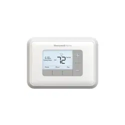
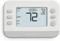
1. Check that the following items are included:

 If any of the items shown above are missing, call Honeywell Customer Care at 1-800-468-1502 before returning the thermostat to the store.
2. Check that you have everything required for the installation:
- Two AA alkaline batteries
- No. 2 Phillips screwdriver and standard pocket screwdriver
- Drill
- Drill bitóuse 3/16 in. for drywall; use 7/32 in. for plaster
- Level (optional)
- Hammer
- Pencil
- Electrical tape
Step 2. Follow Important Instructions
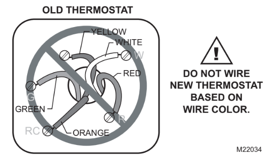
1. Do not connect the wires to the new thermostat based on wire color because damage can occur to the heating and/or cooling system.
These Installation Instructions explain later how to use the enclosed wire labels to correctly mark the wires connected to your old thermostat.
Step 3. Remove Old Thermostat
1. Turn off power at the heating and/or cooling system or fuse/circuit breaker panel.
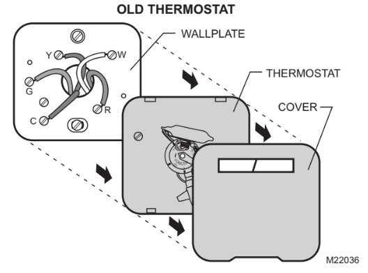
2. Remove the cover from the old thermostat.
3. Remove the old thermostat from the wall or wall- plate. Do not remove the wires.
 MERCURY NOTICE
If you are replacing a thermostat that contains mercury in a sealed tube, do not place your old thermostat in the trash.
Contact your local waste management authority for instructions regarding recycling and the proper disposal of an old thermostat containing mercury in a sealed tube.
Step 4. Follow Special Instructions
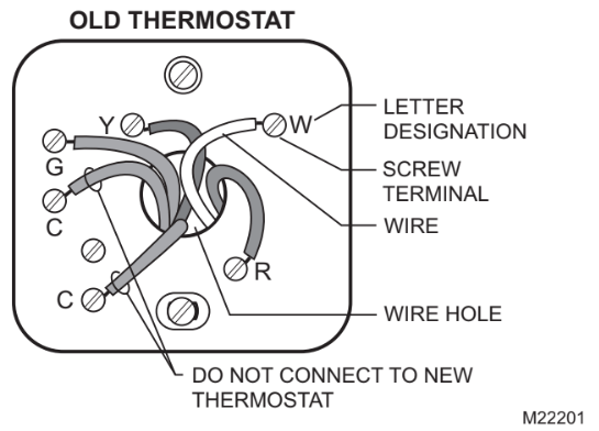
1. If you have two C and/or C1 wires connected to your old thermostat, do not connect them to your new thermostat.
2. Disconnect the C and/or C1 wires. Make sure they do not touch each other or any other wires.
3. Wrap the bare end of each C and/or C1 wire with electrical tape.
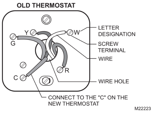
4. If you have only one C and/or C1 wire connected to your old thermostat, connect this wire to C on the new thermostat.
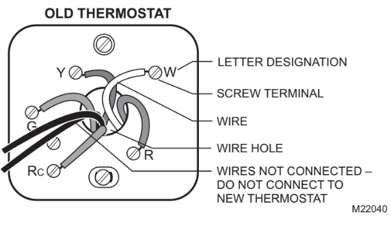
5. If you find any wires not connected to your old thermostat, do not connect them to your new thermostat.
6. Wrap the end of the wires that are not connected with electrical tape.
Step 5. Label Old Thermostat Wires
1. As you disconnect each wire, use the enclosed wire labels to wrap a wire label around each wire that matches the letter designation. Do not allow the wires to fall into the wall opening after the wires are disconnected.
2. Remove any remaining part of the old thermostat from the wall.
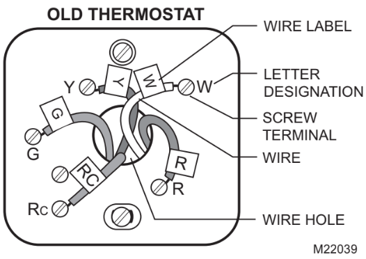
 When connecting the wires to the new thermostat, refer to the wire labels. Do not connect wires to your new thermostat based on the color of the wire.
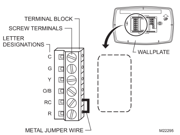
Step 6. Mount New Wallplate to Wall
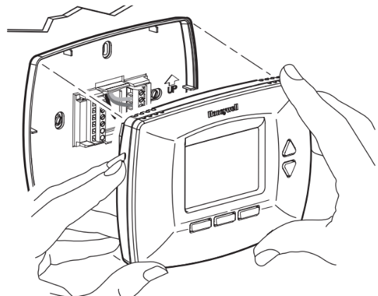
1. Separate the wallplate from the thermostat as shown.
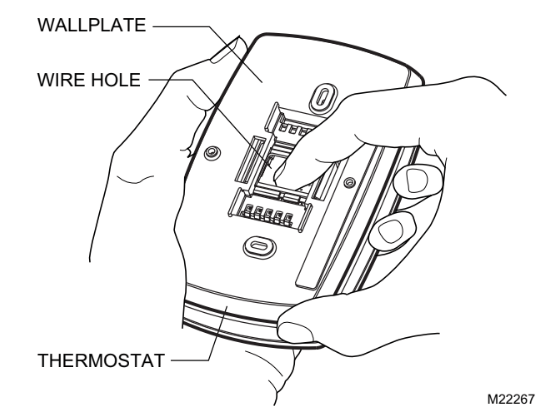
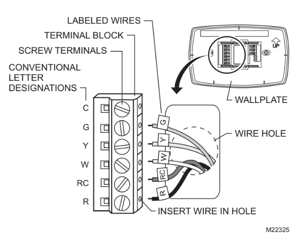
2. Pass the labeled wires through the wire hole on the wallplate.

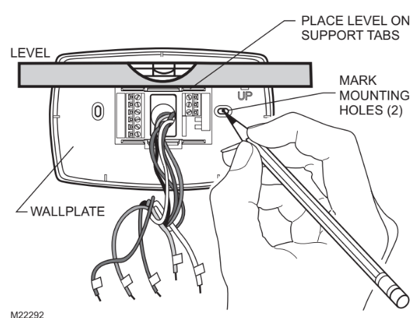
3. Position the wallplate on the wall with the arrow pointing up. Level the wallplate (for appearance only) and mark the two mounting holes with a pencil.
4. Move the wallplate aside and drill holes at the locations marked on the wall. Drill 3/16 in. holes for drywall or 7/32 in. holes for plaster.
5. Tap the wall anchors into the drilled holes until even with the wall surface.
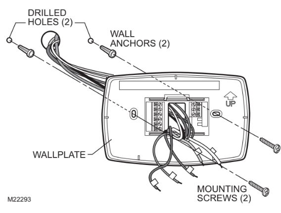
6. Position the wallplate over the wall anchors.
7. Insert the mounting screws into the wall anchors. Check leveling, if desired, and tighten the mounting screws.
Step 7. Connect Wires to New Wallplate
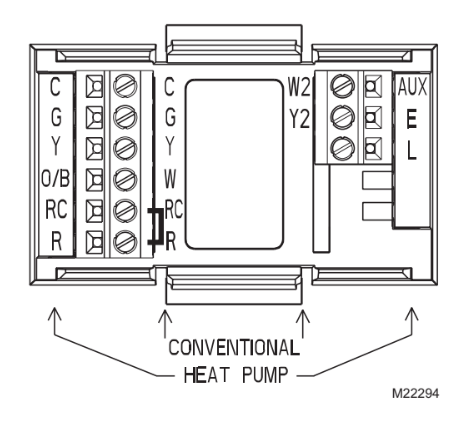
1. Match the labeled wires to the letter designations on the wallplate.
2. Select the correct letter designations to follow for your system. If you have a standard heating and/or cooling system, use the CONVENTIONAL letter designations. If you have a heat pump system, use the HEAT PUMP letter designations to wire the new thermostat.
 See table on page 30 to help you determine if you have a CONVENTIONAL or HEAT PUMP system.
3. If wires are to be connected to both Rc and R, loosen the Rc and R screw terminals and remove the metal jumper wire.
4. If only one of the terminals, Rc or R, is to be connected, leave the metal jumper wire in place.
5. Loosen the screw terminals. Insert the labeled wires into the holes on the side of the terminal block that match the letter designations. Tighten the screw terminals.
6. If any of the labeled wires do not match the letter designations, see next page for wire connections.
7. Compare letter designations on your old and new thermostats. Use the information below if you are wiring a CONVENTIONAL System. Use the information on page 20 if you are wiring a Heat Pump system.
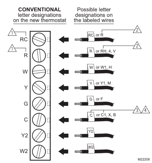
 Do not connect more than one wire to each terminal. Be sure to read the notes referenced in the numbered triangles above. These numbered notes appear on the next page.
NOTES FOR CONVENTIONAL HEATING AND COOLING SYSTEMS
- If wires will be connected to both RC and R on the new thermostat, remove metal jumper wire between RC and R. Leave metal jumper wire in place if only one of the terminals, RC or R, will be connected on the new thermostat.
- If wires were connected to both R and RH terminals on the old thermostat, remove metal jumper wire between RC and R on the new thermostat. Connect the old R to the new RC and the old RH to the new R.
- If two C and/or C1 wires were connected to the old thermostat, do not connect them to the new thermostat. Wrap the bare end of each wire separately with electrical tape and do not use.
- If one C and/or C1 wire was connected to the old thermostat, the wire should be connected to the "C" letter designation on the new thermostat.
8. Compare letter designations on your old and new thermostats. Use the information below if you are wiring a HEAT PUMP system.
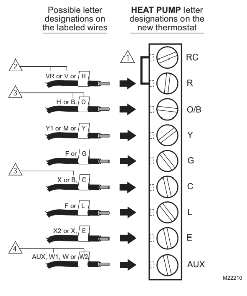
 Be sure to read the note referenced in the numbered triangles above. These numbered notes appear on the next page.
NOTES FOR HEAT PUMP SYSTEMS
- Leave metal jumper wire between RC and R in place.
- If the old thermostat had separate wires on both the V and VR, some system modification is required. Call your local heating and cooling contractor for assistance.
- If the old thermostat had wires on both O and B, be sure to attach the B wire to the C letter designation on the new thermostat. If another wire is already matched to the C, contact Honeywell.
- If the old thermostat had wires on W1, Y1 and W2, some system modification is required. Call your local heating and cooling contractor for assistance.
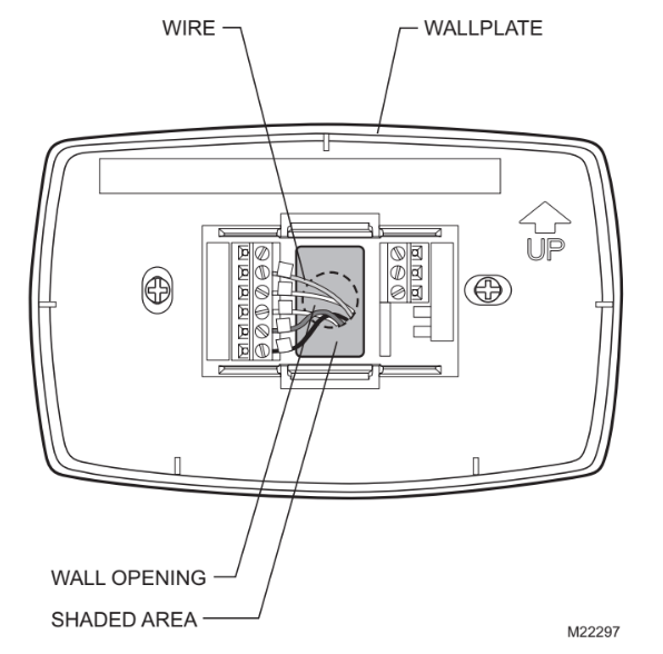
9. Push excess wire back into the wall opening. Keep wires in the shaded area.
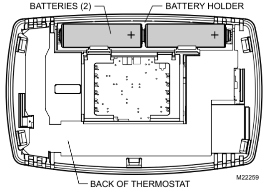
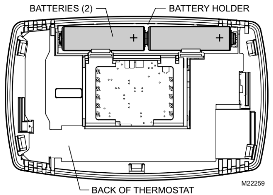
Step 8. Install Batteries
1. Install two fresh AA alkaline batteries on the back of the thermostat as marked on the thermostat.
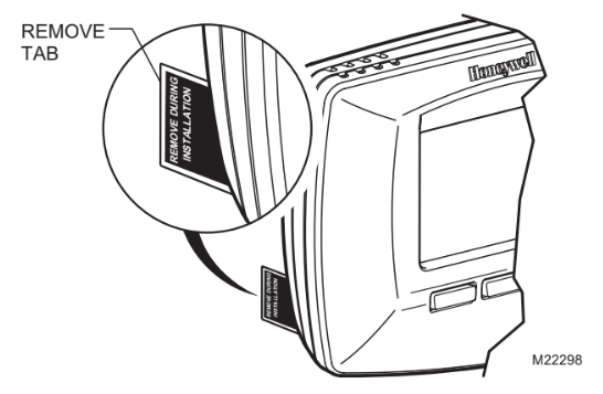
2. Remove tab labeled ìRemove during installationî in the lower right corner of the thermostat back.
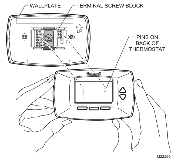
Step 9. Attach New Thermostat to Wallplate
1. Align the screw blocks with the pins on the back of the thermostat.
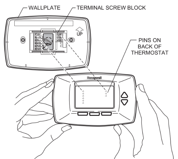
2. Push the thermostat straight onto the wallplate until it snaps into place.
3. Turn on the power at the heating and/or cooling system or fuse/circuit breaker panel.
 If the wires interfere with mounting the thermostat to the wallplate, push the excess wire back into the wall opening.
Step 10. Set the Calendar
This thermostat is designed to automatically keep current time and day in memory for up to ten years, under normal use, once the calendar is set. When the thermostat is first powered, the display is ready to set the calendar.
1. Use Up or Down arrow button to set the Month.
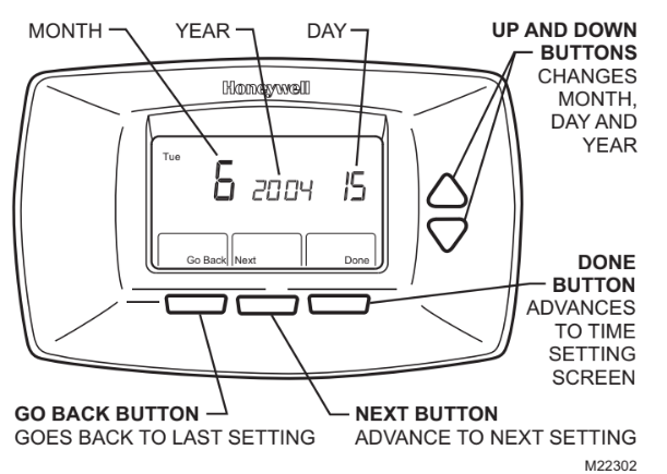
2. Press the Next button to advance to the Date.
3. Use the Up or Down arrow button to set the Date.
4. Press the Next button to advance to the Year.
5. Use the Up or Down arrow button to set the Year.
 The calendar can be set anytime. See Step 11, Configure Installer Setup, for instructions.
6. Press the Done button to advance to the Time.
7. Use the Up or Down arrow button to set the Time.
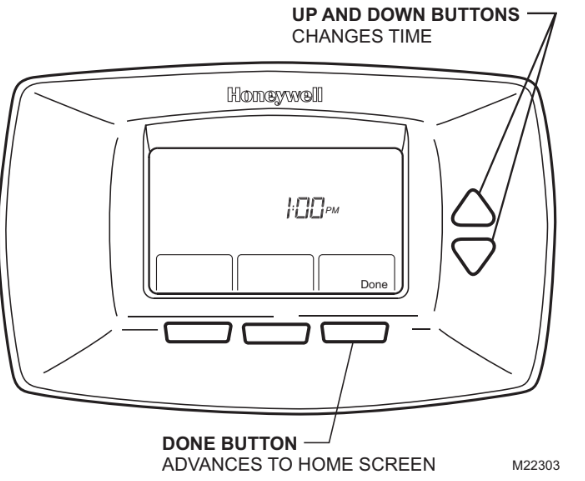
8. Press the Done button.
1. Use the Installer Setup Menu to match your new thermostat to your heating and/or cooling system. Follow the steps in this section to set up your thermostat.
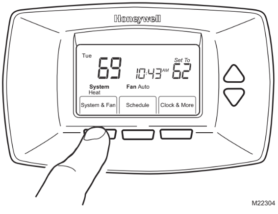
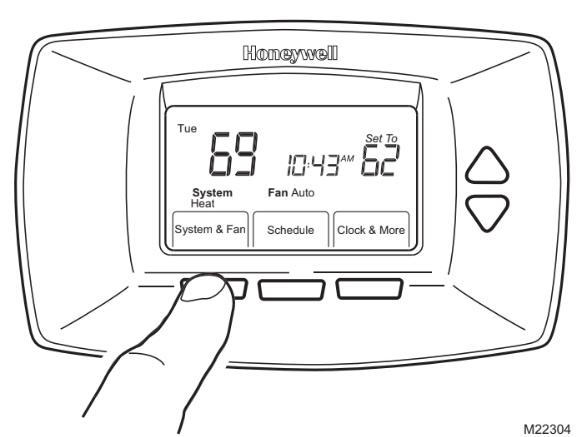
2. Press and release the System button.
3. Press and hold the center button for approximately five seconds, until the screen changes.
4. Release the center button when the display on your thermostat matches the display below.
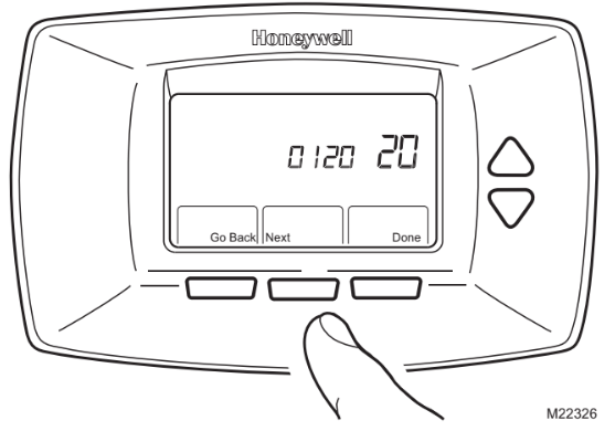
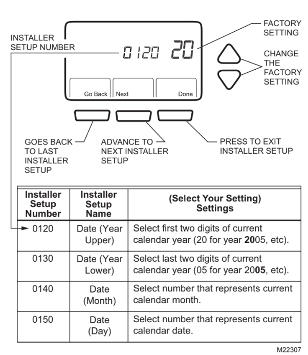
5. Press the Up or Down arrows to select your setting for Installer Setup Number 0120 below.
6. After you select your setting, press the Next button to go to the next Installer Setup Number.
7. Follow steps 5 and 6 to set Installer Setup Numbers 0130, 0140 and 0150 to complete setting the calendar.
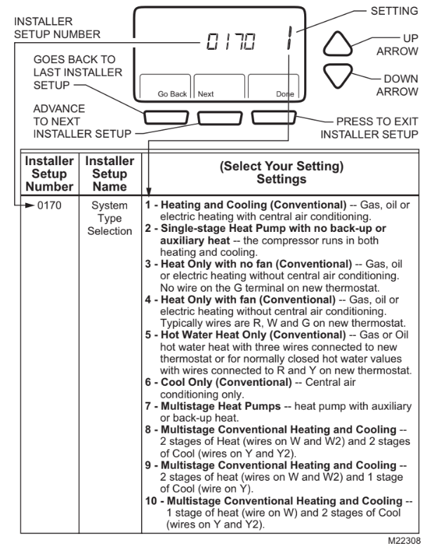
8. Press the Up or Down arrows to select your setting for Installer Setup Number 0170.
9. After you select your setting, press the Next button to go to the next Installer Setup Number.
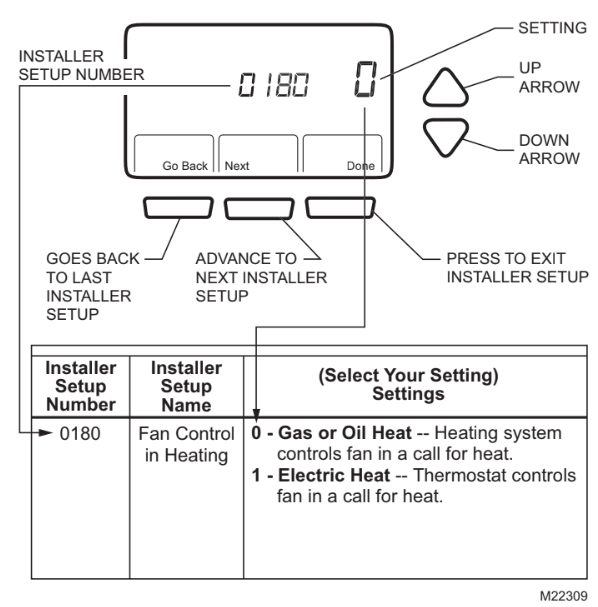
10. If you do not have a number 0180 on the left side of your display, go to the next page.
11. If you have a number 0180 on the left side of your display, press the Up or Down arrow to select your setting for Installer Setup Number 0180.
12. After you select your setting, press the Next button to go to the next Installer Setup Number.
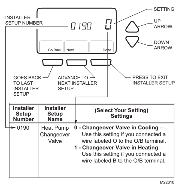
13. If you do not have a number 0190 on the left side of your display, go to the next page.
14. If you have a number 0190 on the left side of your display, press the Up or Down arrow to select your setting for Installer Setup Number 0190.
15. After you select your setting, press the Next button to go to the next Installer Setup Number.
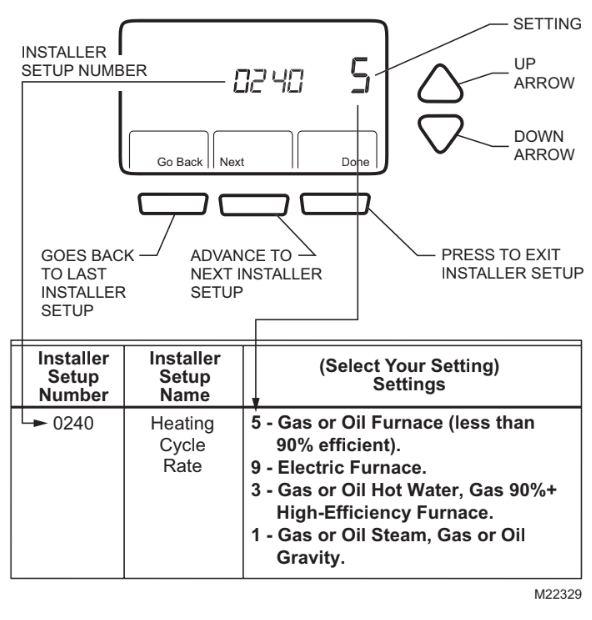
16. If you do not have a number 0240 on the left side of your display, go to the next page.
17. If you have a number 0240 on the left side of your display, press the Up or Down arrow to select your setting for Installer Setup Number 0240.
18. After you select your setting, press the Next button to go to the next Installer Setup Number.
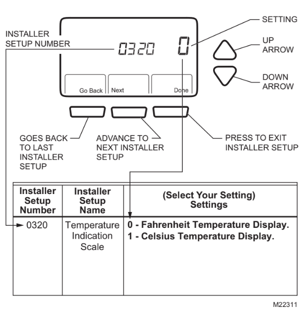
19. Press the Up or Down arrow to select your setting for Installer Setup Number 0320.
20. After you select your setting, press the Next button to go to the next Installer Setup Number.
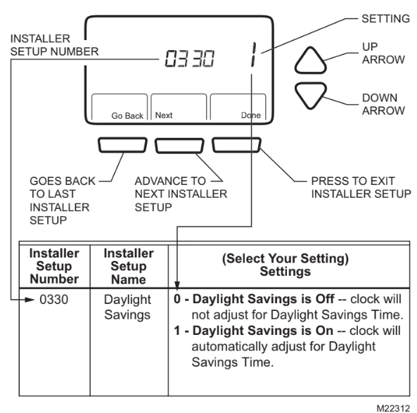
21. Press the Up or Down arrow to select your setting for Installer Setup Number 0330.
22. After you select your setting, press the Next button to go to the next Installer Setup Number.
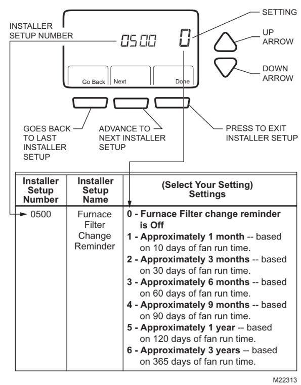
23. Press the Up or Down arrow to select your setting for Installer Setup Number 0500.
24. After you select your setting, press the Next button to go to the next Installer Setup Number.
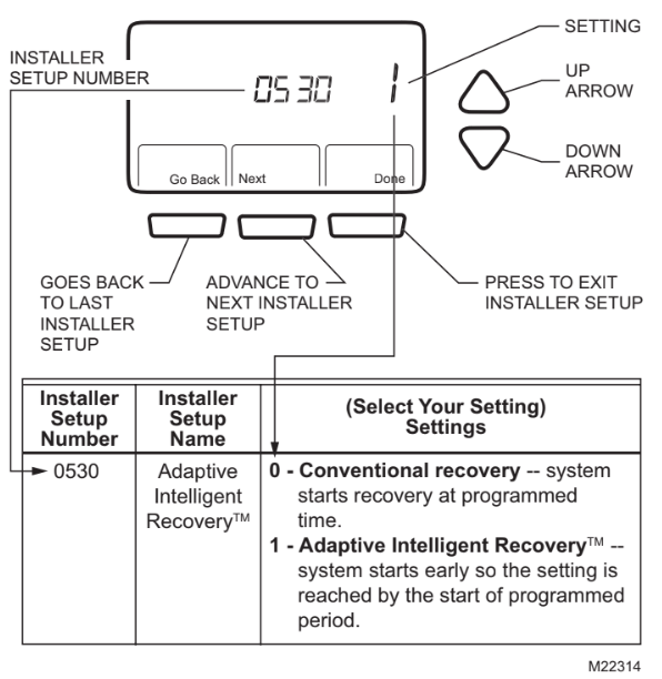
25. Press the Up or Down arrow to select your setting for Installer Setup Number 0530.
26. After you select your setting, press the Next button to go to the next Installer Setup Number.
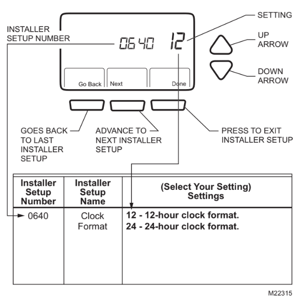
27. Press the Up or Down arrow to select your setting for Installer Setup Number 0640.
28. After you select your setting, press the Done key to exit the Installer Setup and save your settings.
29. Congratulations! The installation of the thermostat is complete.
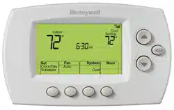
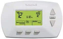
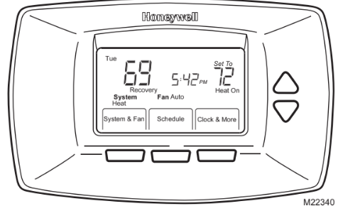
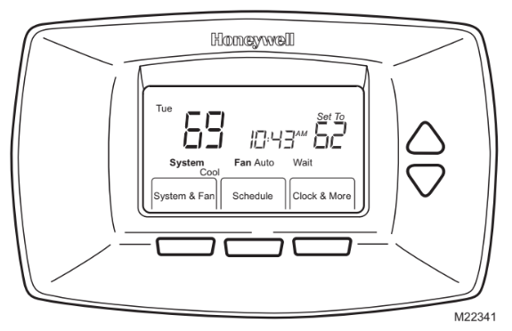
Thermostat
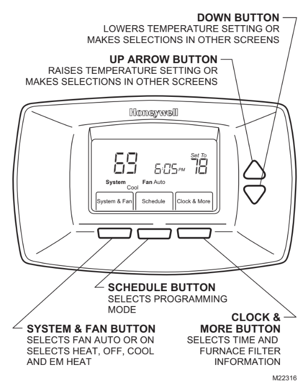
Display
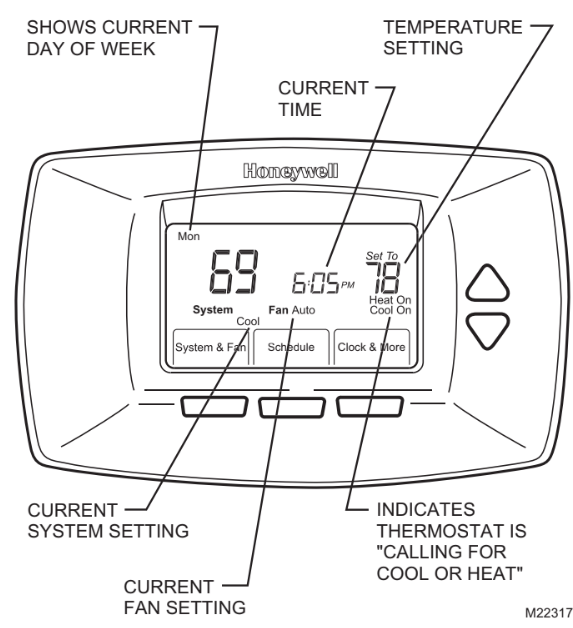
Set System Setting
Set System Setting
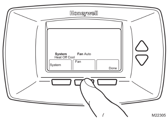
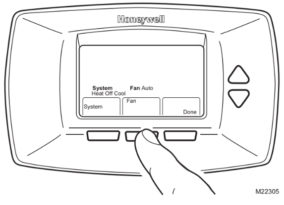
Press the System button to select Heat, Off or Cool:
Heat - Thermostat controls the heating system.
Off - Heating and cooling systems are both off.
Cool - Thermostat controls the cooling system.
Em. Heat (Heat Pump Systems with Auxiliary Heat) - Thermostat controls emergency heat and auxiliary heat, if needed. Heat Pump compressor is not operational.
CAUTION: Equipment Damage Hazard. Air conditioning compressor damage possible. Do not operate cooling system when outdoor temperature is below 50 °F (10 °C).
Set Fan Setting
- Press System & Fan button.
- Press the Fan button to select Auto or On:
Auto - Normal setting for most homes. The fan runs only when the heating or cooling system is on.
On - The fan runs continuously. Use this setting for improved air circulation or for more efficient air cleaning.
Program Your Heating and Cooling Schedule
Your thermostat can control up to four different schedule periods Monday through Friday and Saturday and/or Sunday :
Wake - Period when you awaken and want your home at a comfortable temperature.
Leave - Period when you are away from home and want an energy-saving temperature.
Return - Period when you return home and want your home back to a comfortable temperature.
Sleep - Period when you are asleep and want an energy- saving temperature.
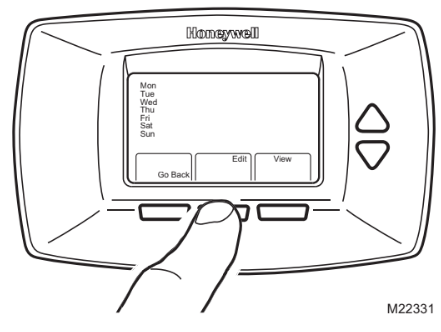
Edit Schedule
1. Press the Schedule button.
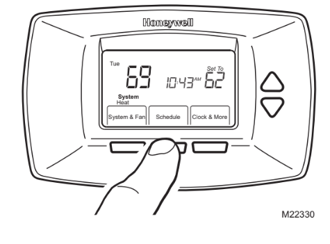
Press the View button to look at the schedule without editing the schedule.
2. Press the Edit button.
3. Monday through Friday flashes. Press the Select Day button to select Monday through Friday. The days selected are scheduled with the same times and temperatures. Checkmarks appear next to the days selected.
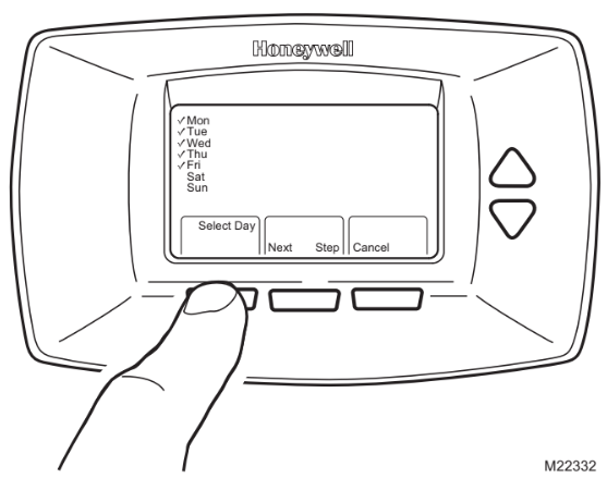
You can select Mon-Fri as a block of days and select Saturday and Sunday separately. Use the Up and Down buttons to move up and down the list of days. Use the Select Day or DeSelect Day button to select the days you want to schedule.
4. Press the Next Step button. Once pressed, Wake flashes to show it is selected.
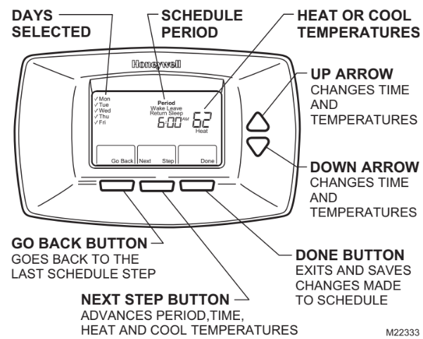
5. Press the Next Step button to select the Wake time.
6. Use the Up and Down arrow buttons to change the time.
7. Press the Next Step button to select the Heating temperature.
8. Use the Up and Down arrow buttons to change the temperature.
9. Press the Next Step button to select the Cooling temperature.
10. Use the Up and Down arrow buttons to change the temperature.
11. Repeat steps 5 through 10 for the Leave, Return and Sleep schedules.
12. When complete, press the Done button. ìSavedî appears on the display to indicate changes are being saved to the day(s) selected.
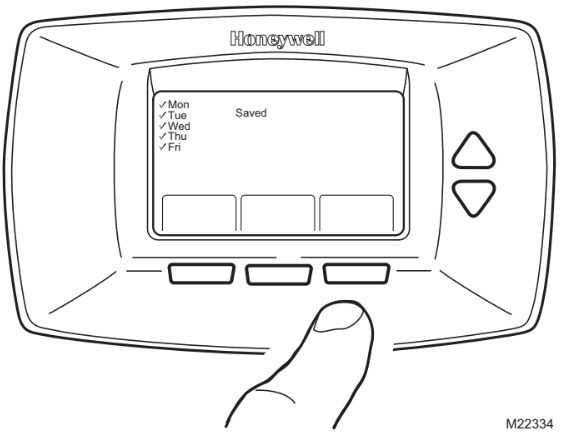
13. To set a program schedule for Saturday and Sunday, repeat steps 1 through 12.
To select Saturday and/or Sunday to schedule, use the Down arrow button until Sat or Sun is flashing.
When the desired day(s) is flashing, press the Select Day button.
Set Time
Set Time
1. Press Clock & More button.
2. Use the Up and Down arrow buttons to set the current time.
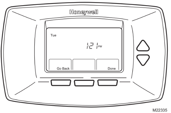
3. Press the Done button.
The current day of the week should already be set correctly. If not, see Step 11, Configure Installer Setup.
Set Temperature Overrides
Hold Temperature Until (Temporary Hold)
Hold temperature temporarily until the next scheduled period time.
1. Press the Up or Down arrow buttons next to the temperature you want to adjust. " Temporary " appears on the display above the set temperature.
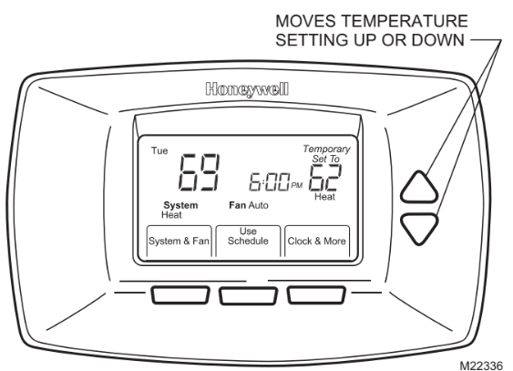
2. Press the Use Schedule button to cancel "Temporary" temperature and resume schedule.
Permanent Hold
Permanent Hold changes the temperature setting until Permanent Hold is cancelled.
1. Use the Up or Down arrow buttons to set the temperature you want during the hold.
2. Press the Hold button. " Permanent Hold" shows on the display.
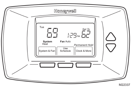
3. Press the Use Schedule button to cancel "Permanent Hold" and resume the schedule.
The display shows Permanent Hold until it is cancelled.
Use Your Filter Timer
The Filter Timer notifies you when to change your furnace filter.
Reset Filter Timer
1. "Change Filter" appears on the display when the filter timer expires.
2. Press the Reset button to restart the filter timer.
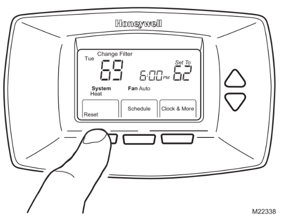
See Step 11 to turn the Filter Timer Change Reminder feature on or off.
View or Reset The Remaining Change Filter Time
1. Press the Clock & More button.
2. Press the Next button.

3. Press the Reset button to Restart the filter timer, if desired.
4. Press the Done button.
Understand Temperature Recovery Feature
Your thermostat comes with a feature called Adaptive Intelligent Recovery™, which eliminates all guesswork when setting your schedule. How long does it take the furnace to warm your house in the morning before you get out of bed or how long does it take the air conditioner to cool your house in the afternoon before you return from work? No problem. The thermostat determines that for you.
Simply set your program schedule to the time you want the house to be at your comfort temperature. The thermostat then turns on the heating or cooling at just the right time to have your home reach your scheduled temperature at your scheduled time.
For exampleóyou get out of bed at 6:00 AM and want the temperature to be 70°F. Set the Wake period for 6:00 AM and
F. The thermostat then turns on the heat before 6:00 AM to raise the temperature to 70°F by 6:00 AM.
The thermostat alerts that the heating or cooling system is coming on before a scheduled time when "Recovery" shows on the screen.
It takes about a week for the thermostat to adjust to local weather, your schedule, the construction of your home and your heating and/or cooling system. Each day it adjusts the next day ís recovery start time accordingly.
Replace Batteries
1. When the LO Battery indicator is flashing, replace the batteries promptly with two fresh AA alkaline batteries.

2. Remove thermostat from the wall plate by pulling straight out.
3. Remove the old batteries and insert two fresh AA alkaline batteries, as marked on the thermostat.
4. Align the screw blocks with the pins on the back of the thermostat.
5. Push the thermostat straight onto the wall plate until it snaps into place.
Review Battery Tips
- Replace the batteries as soon as LO Batt flashes in the display. The LO Battery indicator flashes in the display one month before the batteries run down completely.
- Always use fresh AA alkaline batteries. Non-alka- line batteries do not last as long and can leak, causing thermostat damage.
- Although the thermostat has a Low Battery indica- tor, replace the batteries once a year to prevent the thermostat and heating/cooling system from shut- ting down due to lack of battery power.
- As a precaution, replace the batteries when leaving your home for more than a month to prevent your heating/cooling system from shutting down if the batteries run down completely.
Built-in Compressor Protection
The RTH7400D Thermostat has built-in compressor protection (minimum-off timer) that prevents the compressor from restarting too early after a shutdown.
The minimum-off timer is activated after the compressor turns off.
If there is a call during the minimum-off timer, the thermostat shows "Wait" in the display.
When the minimum-off timer expires, "Cool On" or "Heat On" appears solidly in the display and the compressor and fan turn on.
Troubleshooting Tips
Display is blank.
- Check that fresh AA alkaline batteries are installed as marked on the thermostat.
Temperature settings do not change.
Check that the temperature settings are:
- Heating 40°F to 90°F(4.5°C to 32°C).
- Cooling 50°F to 99°F (10°C to 37°C).
Heating system does not turn on.
- Set the system to Heat by pressing the System button.
- Check the heat temperature setting to be sure it is set above the room temperature and "Heat On" shows solidly in the display.
- Check the circuit breaker to be sure it is not tripped.
- Check power switch at heating and/or cooling system to be sure it is on.
- Check the furnace door to be sure it is closed securely.
- Wait five minutes for the heating system to respond.
- If all of this was checked, contact your local heating and cooling contractor.
Cooling system does not turn on.
- Set the system to Cool by pressing the System button.
- Check the cool temperature setting to be sure it is set below the room temperature and "Cool On" shows solidly in the display.
- Check the circuit breaker to be sure it is not tripped.
- Check the power switch at the heating and/or cooling system to be sure it is on.
- Check the furnace door to be sure it is closed securely.
- Wait five minutes for the cooling system to respond.
- If all of this was checked, contact your local heating and cooling contractor.
Cannot set System setting to Cool.
Check Installer Setup Number 0170, Heating and/or Cooling System Type; make sure the setting matches the installed heating and/or cooling system.
"Heat On" is not shown in the display.
Set the System setting to Heat and set the temperature setting above the room temperature. If "Heat On" is shown solidly in the display, but the heating system does not turn on, see ìHeating system does not turn onî in the Troubleshooting Tips.
"Cool On" is not shown in the display.
Set the System setting to Cool and set the temperature setting below the room temperature. If "Cool On" is shown solidly in the display, but the cooling system does not turn on, see ìCooling system does not turn onî in the Troubleshooting Tips.
"Wait" shows in the display.
Compressor minimum-off timer is active. Wait up to five minutes for the cooling or heating system to turn on.
Fan does not turn on in a call for heat (electric fur- naces only).
Check Installer Setup Number 0180, Fan Control in Heating, and make sure it is set to Electric Heat.
Heat pump puts out cool air in the heat mode and warm air in the cool mode (heat pumps only).
Check Installer Setup Number 0190, Heat Pump Changeover Valve, and make sure the setting matches the changeover required by the installed heat pump.
Both the heating and cooling systems are running at the same time.
- Check Installer Setup Number 0170, Heating and/or Cooling System Type, and make sure the setting matches the installed heating and/or cooling system.
- Check and make sure the bare portions of the wires are not touching.
Heating system is running in cool mode.
Check Installer Setup Number 0170, Heating and/or Cooling System Type, and make sure the setting matches the installed heating and/or cooling system.
Heating system does not turn off and the heat temperature setting is set below the room temperature ("Heat On" is not shown in display).
Check Installer Setup Number 0170, Heating and/or Cooling System Type, and make sure the setting matches the installed heating and/or cooling system.
Red LED is on in the upper left corner and the Heat Pump is not working.
A system monitor is wired to the thermostat L terminal. See Heating or Cooling system does not turn on in the Troubleshooting Tips.