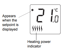
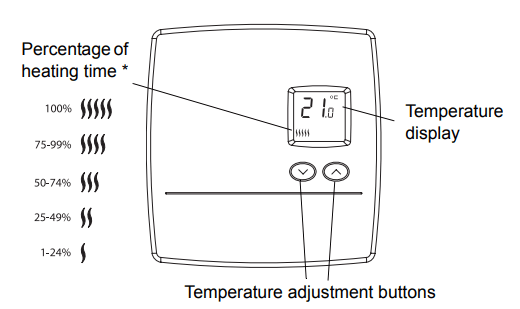
* The thermostat displays the percentage of heating time required to maintain the desired temperature. For example, is displayed when heating is activated 40 percent of the time.
Applications
The RLV3100 thermostat can be used to control an electric heating system such as an electric baseboard heater, a radiant ceiling, a radiant floor, a convector, etc.
The thermostat cannot be used with the following:
a resistive load under 2 A
a resistive load over 12.5 A
systems driven by a contactor or a relay (inductive load)
fan-forced heating systems
central heating systems
Supplied Parts
One (1) thermostat
Two (2) 6-32 mounting screws
Two (2) solderless connectors
Installation Procedure
TURN OFF POWER OF THE HEATING SYSTEM AT THE MAIN POWER PANEL TO AVOID ELECTRIC SHOCK
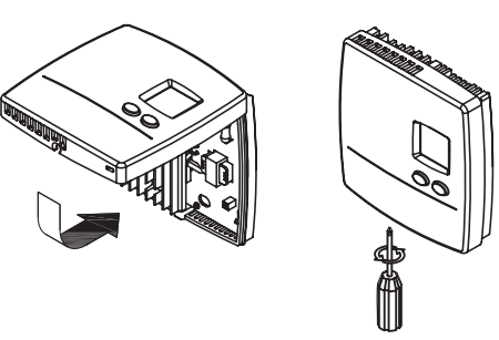
Loosen the screw underneath the thermostat and separate the front plate from the base plate.
NOTE: The screw cannot be completely removed.
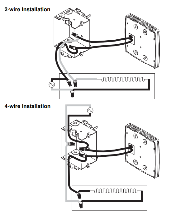
Connect the thermostat wires to the power and to the load using solderless connectors for copper wires. The thermostat wires are not polarized; meaning either wire can be connected to the load or to the power supply.
NOTE: All cables and connections must comply with local electrical codes. This thermostat has tinned copper wires for line and load connections. Special CO/ALR solderless connectors must be used if these wires will be connected to aluminium conductors.
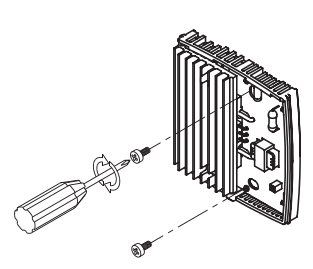
Mount the back plate to the electrical box using the provided screws. Insert the screws through the left or right pair of mounting holes of the back plate.
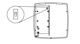
Set the switch on the back of the front plate to °C or °F to select the temperature display format.
Re-install the front plate of the thermostat on the base plate and secure it in place with the screw underneath the thermostat.
NOTE: If there is a protective film or sticker on the display, peel it off.
Apply power to the heating system. Verify the installation by checking that the heater can be turned On and Off by raising and lowering the setpoint using the buttons.
ATTENTION: Keep the thermostat's air vents clean and free from obstructions at all times.
Temperature Display and Setting
The thermostat normally displays the actual (measured) temperature.
To view the set temperature (setpoint), press once on either of the temperature adjustment buttons.
To change the setpoint, press the appropriate button until the desired value is displayed.
NOTE: The display is backlit for 10 seconds when either button is pressed.
Power Outage
The setpoint is stored in non-volatile memory and is not erased when there is a power outage.
Troubleshooting
PROBLEM
SOLUTIONS
Thermostat is hot
This is normal. Under normal operation, the thermostat housing can reach a temperature between 35 °C (95 °F) and 40 °C (104 °F).
Displayed temperature is wrong.
Correct if any the following conditions applies:
The thermostat is exposed to air draft.
The sticker on the thermostat’s screen has not been removed.
The thermostat is located near or above a heat source such as a light dimmer
Display disappears and reappears after a few minutes
The thermal protection device on the heater was temporarily opened. This can happen if the heater is obstructed by furniture or curtain and has overheated, or if the heater’s thermal protection device is too sensitive.
Display looks faded when heating is activated.
The heating system is less than the required minimum load. This thermostat cannot be used below that rating.
Specifications
Supply: 240 VAC, 50/60 Hz
Minimum load: 500 W (2 A resistive only)
Maximum load: 3000 W (12.5 A resistive only)
Display range: 0 to 50°C (32 to 122°F)
Setpoint range: 5 to 30°C (40 to 85°F)
Resolution: 0.5°C (1°F)
Storage: -20 to 50°C (-4 to 120°F)
Dimensions: 126 x 121 x 31 mm (5.0 x 4.8 x 1.2 inches)
Approval: c UL us
Q&A
1. Has anybody noticed a difference in the electric usage between these and the old mercury, analog thermostats (i.e. lower electric bill)?
First bill after installation was 3.00 more. However, the weather has been colder. I set the thermos at 50 degrees and leave for the winter. Old thermos were never precise and could have been set lower as I was questing.
2. Sometimes I find the screen blank and when I press a button it displays 15 and then 22 and then goes back to normal. It is something wrong maybe?
Assuming you have your unit set to c rather than f those may be normal numbers. If that is true then the first number after sleep mode would be set temp and second would be actual temp.
3. I can hear pinging sounds the baseboard used to make every 30ish min(old tstat) now every 15 seconds once it reaches the desired temp. Is this normal?
The pinging is heater expansion, most newish baseboards have none. With fan setting on, unit cycles with a total on-off cycle length of 5 mnutes. With fan setting off, it cycles length is 15 seconds. I use with the longer setting on all my 4 thermostats, no effect felt on room temp fluctuations. Slight dimming of some room lights on sensitive dimming switches less annoying.
4. Confused on the wiring. I have three wires black, white, and red. This unit only has two wires. So what goes where?
The first thing you need to know is that having a black, white, and red wire is perfectly normal in a 240 volt circut, and this unit is designed to accomodate both a 2-wire and 3-wire install. I have installed several of these units in my shore house and all of the installations were two wire. Since in many cases a picture is worth a thousand words, copy and paste the following link into your computers browser and have a look at the pictures for both the 2-wire and 3-wire insallation. I think when you see the 3-wire installation diagram your question will be answered.
5. Does this display the temp of the room?
The thermostat will continuously show the inside temperature. If you press the up or down button once you will see the set temperature displayed for about 5 seconds and then will go back to show the room temperature.
 is displayed when heating is activated 40 percent of the time.
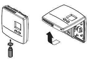
 buttons.