This thermostat can be used to control an electric heating system such as a baseboard heater, a radiant ceiling, ot a convector.
The thermostat CANNOT be used with:
• a resistive load under 0.83 A
• a resistive load over 8.3 A
• a system driven by a contactor or a relay (inductive load)
• a fan-forced heating system (e.g. : fan-forced convertor)
• a central heating system
SUPPLIED PARTS
• One (1) thermostat
• Two (2) 6-32 mounting screws
• Two (2) solderless connectors
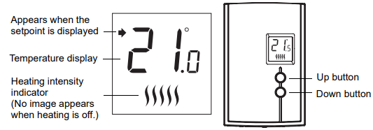
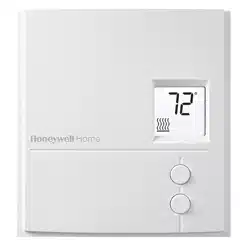
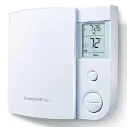
Temperature display and setting
The thermostat normally displays the actual (ambient) temperature.
• To view the setpoint temperature, briefly press the Up or Down button. The setpoint will be displayed for 5 seconds.
• To change the setpoint temperature, press the Up or Down button until the desired value is displayed.
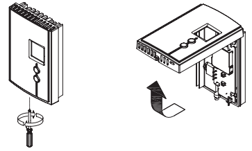
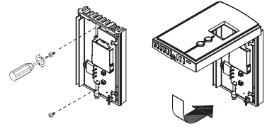
Removing the faceplate
TURN OFF POWER OF THE HEATING SYSTEM AT THE MAIN POWER PANEL TO AVOID ELECTRIC SHOCK.
Loosen the screw holding the faceplate to the base. The screw cannot be completely removed and remains captive on the base. Remove the faceplate from the base by pulling the bottom half.
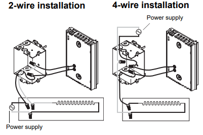
Wiring
Connect either one of the thermostat wires to the heater wire and the other one to the power supply wire using solderless connectors for copper wires.
NOTE: All cables and connections must conform to the local electrical code. Special CO/ALR solderless connectors must be used when connecting with aluminium conductors.
Installing the faceplate
Install the base onto an electrical box.
Reinstall the faceplate on the base and secure it in place with the screw.
NOTE: Keep the air vents of thermostat clean and unobstructed at all times.
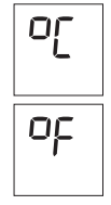
Selecting the temperature display format
To select the temperature display format:
Press the Up and Down buttons for three seconds. The format currently used will be indicated on the screen.
Press the Up or Down button to change the format.
Press the Up and Down buttons for one second (or wait for one minute) to return to the normal display
In case of difficulty
PROBLEM
SOLUTIONS
Thermostat is hot.
This is normal.
Displayed temperature is wrong.
Remediate if any the following conditions exists:
• The thermostat is exposed to air draft.
• The sticker on the thermostat’s screen has not been removed.
• The thermostat is located near or above a heat source such as a light dimmer.
Display disappears and reappears after a few minutes.
The thermal protection device on the heater has temporarily opened. This can happen if the heater is obstructed by furniture or curtain and has overheated, or if the heater’s thermal protection device is too sensitive.
Specifications
- Supply: 120/240 VAC, 50/60 Hz
- Minimum load: 0.83 A (resistive only) 200 W @ 240 VAC 100 W @ 120 VAC
- Maximum load: 8.3 A (resistive only) 2000 W @ 240 VAC 1000 W @ 120 VAC
- Display range: 0°C to 50°C (32°F to 99°F)
- Setpoint range: 5°C to 30°C (40°F to 85°F)
- Storage: -20°C to 50°C (-4°F to 120°F)
- Heating cycle length: 15 seconds
- Permanent memory: You do not need to adjust the temperature following a power outage.