Loading ...
Loading ...
Loading ...
26 | perlick.com/residential
PERLICK RESIDENTIAL ICE MAKER MANUAL
CONDENSER
Check the condenser once a year, and clean if required by
following the steps below. More frequent cleaning may be
required depending on locaon.
Condenser ns are sharp. Use care when
cleaning.
1. Move the control switch to the “OFF” posion, then
unplug the appliance from the electrical outlet
To reduce the risk of electric shock, do not
touch the control switch or plug with damp hands.
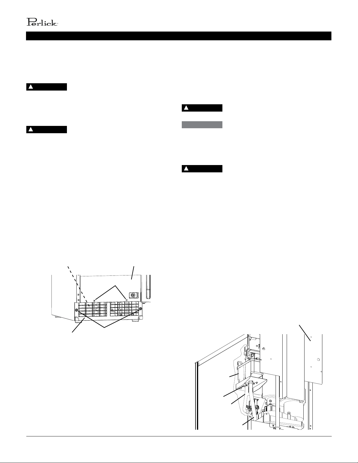
2. Remove the screws securing the front panel, then
remove it (See Fig. 40).
3. Remove the screws securing the louver, then
remove it.
4. Use a brush aachment on a vacuum cleaner to gently
clean the condenser ns. Do not use too much force,
otherwise the ns could be damaged.
5. Replace the louver and front panel in their correct
posions. Ensure that the screws are securely in place.
6. Plug the appliance back in. Move the control switch to
the “ICE” posion to start the automac ice making
process.
DANGER
!
Front Panel
Louver
Fig. 40
Screws
Screws
Condenser
DANGER
!
MAINTENANCE / PREPARING THE APPLIANCE FOR PERIODS OF NON-USE
PREPARING THE APPLIANCE FOR
PERIODS OF NON-USE
During extended periods of non-use, extended absences, or in
sub-freezing temperatures, follow the instrucons below. When
the appliance is not used for two or three days under normal
condions, it is sucient to move the control switch to the
“OFF” posion.
Only qualied service technicians should
service the appliance.
During extended periods of non-use,
extended absences, or in sub-freezing temperatures, follow the
instrucons below to reduce the risk of costly water damage.
1. Move the control switch to the “OFF” posion.
To reduce the risk of electric shock, do not
touch the control switch or plug with damp hands.
2. Close the water supply line shut-o valve, then open
the water supply line drain valve. See Fig. 31.
3. Allow the line to drain by gravity.
4. Move the control switch to the “DRAIN” posion.
5. Allow the water system to drain for 1 minute.
6. Aach a compressed air or carbon dioxide supply to
the water supply line drain valve.
7. Move the control switch to the “ICE” posion.
8. Blow the water supply line out using the compressed
air or carbon dioxide supply.
9. Close the water supply line drain valve.
10. Move the control switch to the “OFF” posion, then
unplug the appliance from the electrical outlet.
11. Remove the screws securing the upper rear panel,
then remove it (See Fig. 41).
DANGER
!
WARNING
DANGER
!
Fig. 41
Upper Rear Panel
Clamp
Reservoir
Outlet
Hose
Reservoir
Overow Hose
Loading ...
Loading ...