NOTE: ONLY use the bolts removed from the garage door opener. Place the garage door opener on the packing material to prevent scratching.
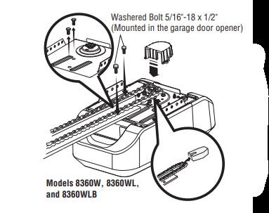
1. Remove the two bolts from the top of the garage door opener.
2. Align the rail and the styrofoam over the sprocket. Cut the tape from the rail, chain, and styrofoam.
3. Fasten the rail with the previously removed bolts.
4. Position the chain around the garage door opener sprocket.
5. Install the sprocket cover by squeezing the sides and inserting the tabs into the slots on the garage door opener.
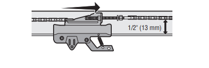
Tighten the Chain
1. Loosen the inner nut and lock washer on the trolley threaded shaft.
2. Tighten the outer nut until the chain is a 1/2" above the base of the rail at the midpoint of the rail.
3. Re-tighten the inner nut.
Slack in the chain is normal when the door is closed. No readjustment is necessary.
Installation
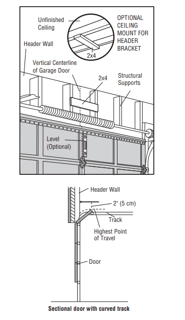
Determine the Header Bracket Location
Install the Header Bracket
You can attach the header bracket either to the wall above the garage door, or to the ceiling. Follow the instructions which will work best for your particular requirements. Do not install the header bracket over drywall. If installing into masonry, use concrete anchors (not provided).
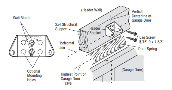
OPTION A - WALL INSTALLATION
1. Center the bracket on the vertical centerline with the bottom edge of the bracket on the horizontal line as shown (with the arrow pointing toward the ceiling).
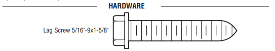
2. Mark the vertical set of bracket holes (do not use the holes designated for ceiling mount). Drill 3/16" pilot holes and fasten the bracket securely to a structural support with lag screws.
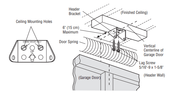
OPTION B - CEILING INSTALLATION
1. Extend the vertical centerline onto the ceiling as shown.
2. Center the bracket on the vertical mark, no more than 6" (15 cm) from the wall. Make sure the arrow is pointing toward the wall. The bracket can be mounted flush against the ceiling when clearance is minimal.
3. Mark the side holes. Drill 3/16" pilot holes and fasten bracket securely to a structural support with the hardware provided.
Attach the Rail to the Header Bracket
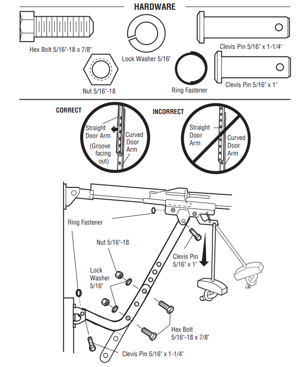
1. Align the rail with the header bracket. Insert the clevis pin through the holes in the header bracket and rail. Secure with the ring fastener.
NOTE: Use the packing material as a protective base for the garage door opener
Position the Garage Door Opener
1. Remove the packing material and lift the garage door opener onto a ladder.
2. Fully open the door and place a 2x4 (laid flat) under the rail.
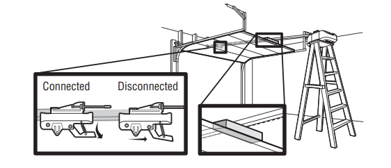
A 2x4 is ideal for setting the distance between the rail and the door. If the ladder is not tall enough you will need help at this point. If the door hits the trolley when it is raised, pull the trolley release arm down to disconnect the inner and outer trolley. Slide the outer trolley toward the garage door opener. The trolley can remain disconnected until instructed.
Hang the Garage Door Opener
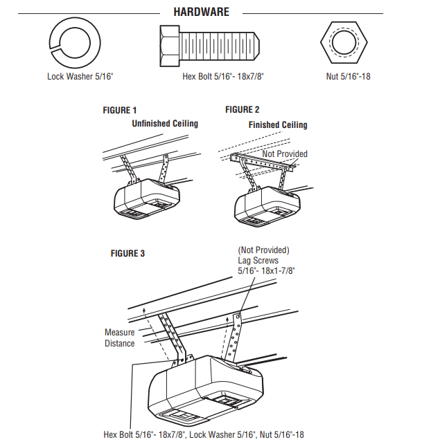
Hanging your garage door opener will vary depending on your garage. Two representative installations are shown. Yours may be different. Hanging brackets should be angled (Figure 1) to provide rigid support. On finished ceilings (Figure 2), attach a sturdy metal bracket to structural supports before installing the opener. This bracket and fastening hardware are not provided.
1. Measure the distance from each side of the motor unit to the structural support.
2. Cut both pieces of the hanging bracket to required lengths.
3. Drill 3/16" pilot holes in the structural supports.
4. Attach one end of each bracket to a support with 5/16"-18 x 1-7/8" lag screws (not provided).
5. Fasten the opener to the hanging brackets with 5/16"-18 x 7/8" hex bolts, lock washers and nuts.
6. Check to make sure the rail is centered over the door (or in line with the header bracket if the bracket is not centered above the door).
7. Remove the 2x4. Operate the door manually. If the door hits the rail, raise the header bracket.
Install the Light Bulbs
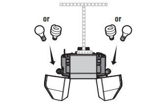
1. Pull on the top center of the light lens and rotate the light lens down.
2. Insert an A19 incandescent (100W maximum) or compact fluorescent (26W, 100W equivalent) light bulb into the light socket.
NOTE: DO NOT use halogen, short neck, or specialty light bulbs as these may overheat the end panel or light socket. DO NOT use LED bulbs as they may reduce the range or performance of your remote control(s).
3. Rotate the lens up to close.
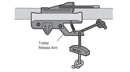
Attach the Emergency Release Rope and Handle
1. Insert one end of the emergency release rope through the handle. Make sure that “NOTICE” is right side up. Secure with an overhand knot at least 1" (2.5 cm) from the end of the rope to prevent slipping.
2. Insert the other end of the emergency release rope through the hole in the trolley release arm. Mount the emergency release within reach, but at least 6 feet (1.83 m) above floor, avoiding contact with vehicles to prevent accidental release and secure with an overhand knot.
NOTE: If it is necessary to cut the emergency release rope, seal the cut end with a match or lighter to prevent unraveling. Ensure the emergency release rope and handle are above the top of all vehicles to avoid entanglement.
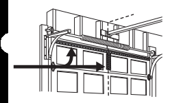
Install the Door Bracket
A horizontal and vertical reinforcement is needed for lightweight garage doors (fiberglass, aluminum, steel, doors with glass panel, etc.) (not provided). A horizontal reinforcement brace should be long enough to be secured to two or three vertical supports. A vertical reinforcement brace should cover the height of the top panel. Contact the garage door manufacturer or installing dealer for opener reinforcement instructions or reinforcement kit.
SECTIONAL DOORS
1. Center the door bracket on the previously marked vertical centerline used for the header bracket installation. Note correct UP placement, as stamped inside the bracket.
2. Position the top edge of the bracket 2"-4" (5-10 cm) below the top edge of the door, OR directly below any structural support across the top of the door.
3. Mark, drill holes and install as follows, depending on your door’s construction:
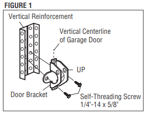
Metal or light weight doors using a vertical angle iron brace between the door panel support and the door bracket:
Drill 3/16" fastening holes. Secure the door bracket using the two self threading screws. (Figure 1)
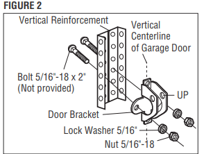
Alternately, use two 5/16"-18x2" bolts, lock washers and nuts (not provided). (Figure 2)
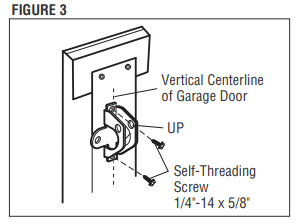
Metal, insulated or light weight factory reinforced doors:
Drill 3/16" fastening holes. Secure the door bracket using the self-threading screws. (Figure 3)
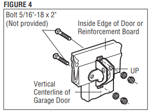
Wood Doors:
Use top and bottom or side to side door bracket holes. Drill 5/16” holes through the door and secure bracket with 5/16"-18 x 2" carriage bolts, lock washers and nuts (not provided). (Figure 4)
Connect the Door Arm to the Trolley
IMPORTANT: The groove on the straight door arm MUST face away from the curved door arm.
1. Close the door. Disconnect the trolley by pulling the emergency release handle. Slide the outer trolley back (away from the door) about 2" (5 cm).
2. Attach the straight door arm to the outer trolley using the clevis pin. Attach with the ring fastener.
3. Attach the curved door arm to the door bracket using the clevis pin. Attach with the ring fastener.
4. Align the straight door arm with the curved door arm. Select two aligned holes (as far apart as possible) and attach using the bolts, nuts and lock washers.
NOTE: If the holes do not line up, reverse the straight door arm. Select two aligned holes (as far apart as possible) and attach using the bolts, nuts and lock washers.
5. Pull the emergency release handle toward the garage door opener until the trolley release arm is horizontal. The trolley will re-engage automatically when the garage door opener is activated.
Operation
Features
Your garage door opener is equipped with features to provide you with greater control over your garage door operation.
Alert2Close
The Alert2Close feature provides a visual and an audible alert that an unattended door is closing.
TIMER-TO-CLOSE (TTC)
The TTC feature automatically closes the door after a specified time period that can be adjusted using a TTC enabled door control (Models 881LMW or 880LMW). Prior to and during the door closing the garage door opener lights will flash and the garage door opener will beep.
myQ
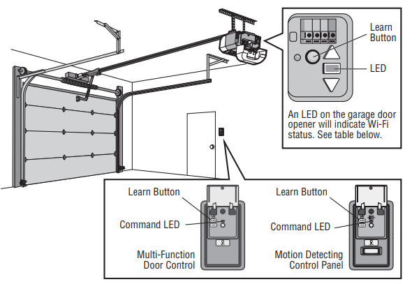
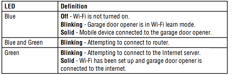
myQ allows you to control your garage door opener from your mobile device or computer from anywhere. myQ technology uses a 900Mhz signal to provide two way communication between the garage door opener and myQ enabled accessories. The garage door opener has an internal gateway that allows the garage door opener to communicate directly with a home Wi-Fi® network and access your myQ account.
THE PROTECTOR SYSTEM® (SAFETY REVERSING SENSORS)
When properly connected and aligned, the safety reversing sensors will detect an obstruction in the path of the infrared beam. If an obstruction breaks the infrared beam while the door is closing, the door will stop and reverse to full open position, and the opener lights will flash 10 times. If the door is fully open, and the safety reversing sensors are not installed, or are misaligned, the door will not close from a remote control. However, you can close the door if you hold the button on the door control or keyless entry until the door is fully closed. The safety reversing sensors do not affect the opening cycle. For more information see page 23.
ENERGY CONSERVATION
For energy efficiency the garage door opener will enter sleep mode when the door is fully closed. The sleep mode shuts the garage door opener down until activated. The sleep mode is sequenced with the garage door opener light bulb; as the light bulb turns off the sensor LEDs will turn off and whenever the garage door opener lights turn on the sensor LEDs will light. The garage door opener will not go into the sleep mode until the garage door opener has completed 5 cycles upon power up.
LIGHTS
The garage door opener light bulbs will turn on when the opener is initially plugged in; power is restored after interruption, or when the garage door opener is activated. The lights will turn off automatically after 4-1/2 minutes. An incandescent A19 light bulb (100 watt maximum) or for maximum energy efficiency a 26W (100W equivalent) compact fluorescent light (CFL) bulb may be used.
Light Feature
The garage door opener is equipped with an added feature; the lights will turn on when someone enters through the open garage door and the safety reversing sensor infrared beam is broken. For added control over the light bulbs on your garage door opener, see page 38 or page 40.
USING YOUR GARAGE DOOR OPENER
The garage door opener can be activated through a wall-mounted door control, remote control, wireless keyless entry or myQ accessory. When the door is closed and the garage door opener is activated the door will open. If the door senses an obstruction or is interrupted while opening the door will stop. When the door is in any position other than closed and the garage door opener is activated the door will close. If the garage door opener senses an obstruction while closing, the door will reverse. If the obstruction interrupts the sensor beam the garage door opener lights will blink 10 times. However, you can close the door if you hold the button on the door control or keyless entry until the door is fully closed. The safety reversing sensors do not affect the opening cycle. The safety reversing sensor must be connected and aligned correctly before the garage door opener will move in the down direction.
BATTERY BACKUP*
The battery backup system allows access in and out of your garage, even when the power is out. When the garage door opener is operating on battery power, the garage door opener will run slower, the light will not function, the Battery Status LED will glow solid orange, and a beep will sound approximately every 2 seconds.
Connect With Your Smartphone
The Wi-Fi Garage Door Opener is compatible with up to 16 myQ enabled accessories. Up to 10 devices can be paired to the Wi-Fi garage door opener’s internal gateway. These devices can be controlled with the myQ app. These devices include any combination of myQ garage door openers, Wi-Fi garage door openers, myQ light controls, myQ gate operators or myQ commercial door operators. A LiftMaster Internet Gateway (828LM) can be added if you need to control more than 10 devices using the myQ app. Up to 6 devices can be paired to garage door opener itself (controlled by garage door opener through 900MHz). These devices include any combination of myQ light controls or a garage door and gate monitor.
You will need:
Wi-Fi enabled smartphone, tablet or laptop
Broadband Internet Connection l Wi-Fi signal in the garage (2.4 Ghz, 802.11b/g/n required), see page 4
Password for your home network (router's main account, not guest network)
myQ serial number located on the garage door opener
Download the myQ App to Set Up an Account and Connect
Open and close your door, get alerts and set schedules from anywhere. Connected smart garage door openers also receive software updates to ensure the opener has the latest operational features.
1. Download the myQ App.
2. Set up an account and connect.
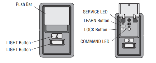
Using the Motion Detecting Control Panel
Up to 2 Smart Control Panels® or 4 of any other Security+ 2.0® door controls can be connected to the garage door opener.
PUSH BAR
Press the push bar to open or close the door.
LIGHT BUTTON
Press the LIGHT button to turn the garage door opener lights on or off. When the lights are turned on they will stay on until the LIGHT button is pressed again, or until the garage door opener is activated. Once the garage door opener is activated the lights will turn off after the specified period of time (the factory setting is 4-1/2 minutes). The LIGHT button will not control the lights when the door is in motion
LEARN A DEVICE
Any compatible remote controls, wireless keyless entry, Wi-Fi garage door openers, ormyQ accessories can be programmed to the garage door opener by pressing the LEARN button on the Motion-Detecting Control Panel, see page 41.
LOCK
The LOCK feature is designed to prevent activation of the garage door opener from remote controls while still allowing activation from the door control and keyless entry. This feature is useful for added peace of mind when the home is empty (i.e. vacation).
AUTOMATIC LIGHT
Motion Sensor (Premium Motion-Detecting Control Panel) Factory default is set to on. This feature automatically turns on the garage door opener lights when motion is sensed. The lights will come on for the set period of time, then shut off. If using the garage door opener light as a work light disable the motion sensor, otherwise the light will turn off automatically if you are beyond the range of the sensor.
Light Feature
The lights will turn on when someone enters through the open garage door and the safety reversing sensor infrared beam is broken.
MAINTENANCE ALERT (MAS)
This feature assists the homeowner in ensuring the garage door opener system stays in good working condition. When the garage door opener needs to be serviced (approximately 4500 garage door opener cycles) the command (yellow) and service (red) LEDs will begin to alternately flash back and forth. The factory setting for the MAS feature is off and can be activated at time of installation. Contact your installing dealer for service.
Maintenance
Maintenance Schedule
EVERY MONTH
Manually operate door. If it is unbalanced or binding, call a trained door systems technician.
Check to be sure door opens and closes fully. Adjust if necessary, see page 30.
Test the safety reversal system. Adjust if necessary, see page 31.
EVERY YEAR
Oil door rollers, bearings and hinges. The garage door opener does not require additional lubrication. Do not grease the door tracks.
Test the battery and consider replacing the battery to ensure the garage door opener will operate during an electrical power outage, see page 32 to test the battery backup.
EVERY TWO TO THREE YEARS
Use a rag to wipe away the existing grease from the garage door opener rail. Reapply a small layer of white lithium grease to the top and underside of the rail surface where the trolley slides.
The Remote Control Battery
To replace the battery, pry open the case in the middle, then at each side with the visor clip. Insert replacement battery positive side up (+). Replace the batteries with only 3V CR2032 coin cell batteries. Dispose of old batteries properly.
Troubleshooting
Diagnostic Chart
Your garage door opener is programmed with self-diagnostic capabilities. The UP and DOWN arrows on the garage door opener flash the diagnostic codes.
DIAGNOSTIC CODE
SYMPTOM
SOLUTION
Up Arrow Flash(es)
Down Arrow Flash(es)
1
1
The garage door opener will not close and the light bulbs flash.
Safety reversing sensors are not installed, connected, or wires may be cut. Inspect sensor wires for a disconnected or cut wire
1
2
The garage door opener will not close and the light bulbs flash.
There is a short or reversed wire for the safety reversing sensors. Inspect safety sensor wire at all staple and connection points, replace wire or correct as needed.
1
3
The door control will not function.
The wires for the door control are shorted or the door control is faulty. Inspect door control wires at all staple and connection points, replace wire or correct as needed.
1
4
The garage door opener will not close and the light bulbs flash.
Safety reversing sensors are misaligned or were momentarily obstructed. Realign both sensors to ensure both LEDs are steady and not flickering. Make sure nothing is hanging or mounted on the door that would interrupt the sensor’s path while closing.
1
5
Door moves 6-8" (15-20 cm) stops or reverses.
Manually open and close the door. Check for binding or obstructions, such as a broken spring or door lock, correct as needed. Check wiring connections at travel module and at the logic board. Replace travel module if necessary.
No movement, only a single click.
Manually open and close the door. Check for binding or obstructions, such as a broken spring or door lock, correct as needed. Replace logic board if necessary.
Opener hums for 1-2 seconds no movement.
Manually open and close the door. Check for binding or obstructions, such as a broken spring or door lock, correct as needed. Replace motor if necessary.
1
6
Door coasts after it has come to a complete stop.
Program travel to coasting position or have door balanced by a trained door systems technician.
2
1-5
No movement, or sound.
Replace logic board.
3
2
Unable to set the travel or retain position.
Check travel module for proper assembly, replace if necessary.
3
3
The battery status LED is constantly flashing green. *
Manually open and close the door. Check for binding or obstructions, such as a broken spring or door lock, correct as needed. If the door is binding or sticking contact a trained door systems technician. If door is not binding or sticking attempt to reprogram travel (refer to page 30).
4
5
Opener runs approximately 6-8" (15-20 cm), stops and reverses.
Communication error to travel module. Check travel module connections, replace travel module if necessary
4
6
The garage door opener will not close and the light bulbs flash.
Safety reversing sensors are misaligned or were momentarily obstructed. Realign both sensors to ensure both LEDs are steady and not flickering. Make sure nothing is hanging or mounted on the door that would interrupt the sensor’s path while closing.
The garage door opener will NOT enter Wi-Fi® LEARN mode:
After the initial installation of the garage door opener, the garage door opener must complete a full cycle (open and closed) before the Wi-Fi LEARN mode can be activated
If there has been a recent power outage, the garage door opener must complete a full cycle before the Wi-Fi LEARN mode can be activated.
See page 36 to activate Wi-Fi LEARN mode.
Cannot connect garage door opener to home Wi-Fi network:
Ensure the myQ Serial number was entered correctly and try again. The myQ characters are between A-F and 0-9 only
Weak Wi-Fi signal in the garage. Ensure the Wi-Fi signal is reaching the garage, see page 4 or visit WiFiHelp.LiftMaster.com for more information.
My door will not close and the light bulbs blink on my motor unit:
The safety reversing sensor must be connected and aligned correctly before the garage door opener will move in the down direction.
Verify the safety reversing sensors are properly installed, aligned and free of any obstructions.
My garage door opener light(s) will not turn off when the door is open:
The garage door opener is equipped with a feature that turns the light on when the safety reversing sensors have been obstructed. This feature can be disabled using the door control, see page 38 or page 40.
My neighbor’s remote control opens my garage door:
Erase the memory from your garage door opener and reprogram the remote control(s).
My vehicle's Homelink® is not programming to my garage door opener:
Depending on the make, model, and year of your vehicle an external adapter may be required. Visit homelink website for additional information.