Swing Gate Operator Long Arm Kit
Model HDLGARM
To reduce the risk of SEVERE INJURY or DEATH:
• Disconnect power (AC solar and battery) before servicing or
installing operator.
• Turn both the AC and battery switches to off position.
• Set the reset switch to the disconnect position.
WARNING: This product can expose you to chemicals including
lead, which are known to the State of California to cause cancer
or birth defects or other reproductive harm. For more information
go to www.P65Warnings.ca.gov
ATTENTION:
A SOLID BRACKET IS ATTACHED TO SHORT ARM LINK ON PACKAGING
FOR SHIPPING PURPOSES ONLY. PLEASE FOLLOW THE INSTRUCTIONS
FOR ARM ASSEMBLY.
Introduction
The long arm kit is for use with LiftMaster
®
gate operator model HDSW24UL. To optimize performance and extend operator life, the long arm kit is
recommended when installing with gates 16 ft. or longer.
See installation manual for gate operator model HDSW24UL for complete installation and safety instructions.
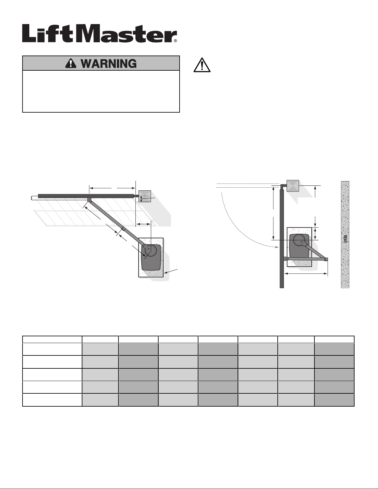
Determine Location for Concrete Pad and Operator
Refer to the illustration to determine the measurements and location of the concrete pad.
Inside
Outside
Inside
Outside
Wall
A
F
B
C
D
10"
(25.4 cm)
DISTANCE
E
Long Arm Section
Short Arm Section
Concrete Pad
Gate Hinge Center
NOTE: There should only
be a maximum of
4" (10.2 cm) from the
center of the hinge to the
edge of the post or
column. If the distance is
greater than 4" (10.2 cm),
entrapment protection for
this area is required.
D MINUS 10"
(25.4 cm)
Dimension (A) thru (E) are from the center of one pivot point to the center of another pivot point.
Suggestion: The dimensions between the gate and the concrete pad is always 10 inches (25.4 cm) less than the dimension D.
Example: D = 42" (106.7 cm), if the dimensions between the gate and the concrete pad is 32" (81.3 cm).
Chart LA
Requires less clearance between gate and wall.
GATE LENGTH A B C D E F DISTANCE
22 ft.
2,500 lbs.max.
88" (2.24 m) 62.5" (1.58 m) 57.5" (1.46 m) 71" (1.80 m) 11" (27.9cm) 3" (7.6 cm) 70" (1.78 m)
20 ft.
2,750 lbs. max.
80" (2.03 m) 58.25" (1.48 m) 52.25" (1.33 m) 65.5" (1.66m) 11" (27.9cm) 3" (7.6 cm) 65.75" (1.67 m)
18 ft,
3,250 lbs. max.
72" (1.83 m) 53" (1.35m) 47" (1.19 m) 58.5" (1.49m) 11" (27.9 cm) 3" (7.6 cm) 60.5" (1.54 m)
16 ft.
3,750 lbs. max.
64" (1.63 m) 48.25" (1.23 m) 41.75" (1.06 m) 52.5" (1.33m) 11" (27.9cm) 3" (7.6 cm) 55.75" (1.42 m)
14 ft.
4,500 lbs. max.
56" (1.42 m) 44.75" (1.14 m) 37.25" (.95 m) 50" (1.27m) 11" (27.9cm) 3" (7.6 cm) 52.25" (1.33 m)

Chart LB - Requires More Clearance Between Gate and Wall
Requires more clearance between gate and wall. Recommended on retrofit installations when operator being replaced is other than LiftMaster
®
.
GATE LENGTH A B C D E F DISTANCE
22 ft.
2,500 lbs.max.
88" (2.24 m) 66.25" (1.68 m) 57.25" (1.45 m) 71" (1.80m) 15" (38.1 cm) 3" (7.6 cm) 73.75" (1.87m)
20 ft.
2,750 lbs. max.
80" (2.03 m) 61.75" (1.57 m) 52" (1.32m) 65.5" (1.66m) 15" (38.1 cm) 3" (7.6 cm) 59.25" (1.51m)
18 ft.
3,250 lbs. max.
72" (1.83 m) 56.5" (1.44 m) 46.75" (1.19 m) 58.5" (1.49 m) 15" (38.1 cm) 3" (7.6 cm) 64" (1.63 m)
16 ft.
3,750 lbs. max.
64" (1.63 m) 51.75" (1.31 m) 41.5" (1.05 m) 52.5" (1.33 m) 15" (38.1 cm) 3" (7.6 cm) 59.25" (1.51 m)
14 ft.
4,500 lbs. max.
56" (1.42 m) 48.25" (1.23 m) 37" (.94m) 50" (1.27 m) 15" (38.1cm) 3" (7.6 cm) 55.75" (1.42 m)
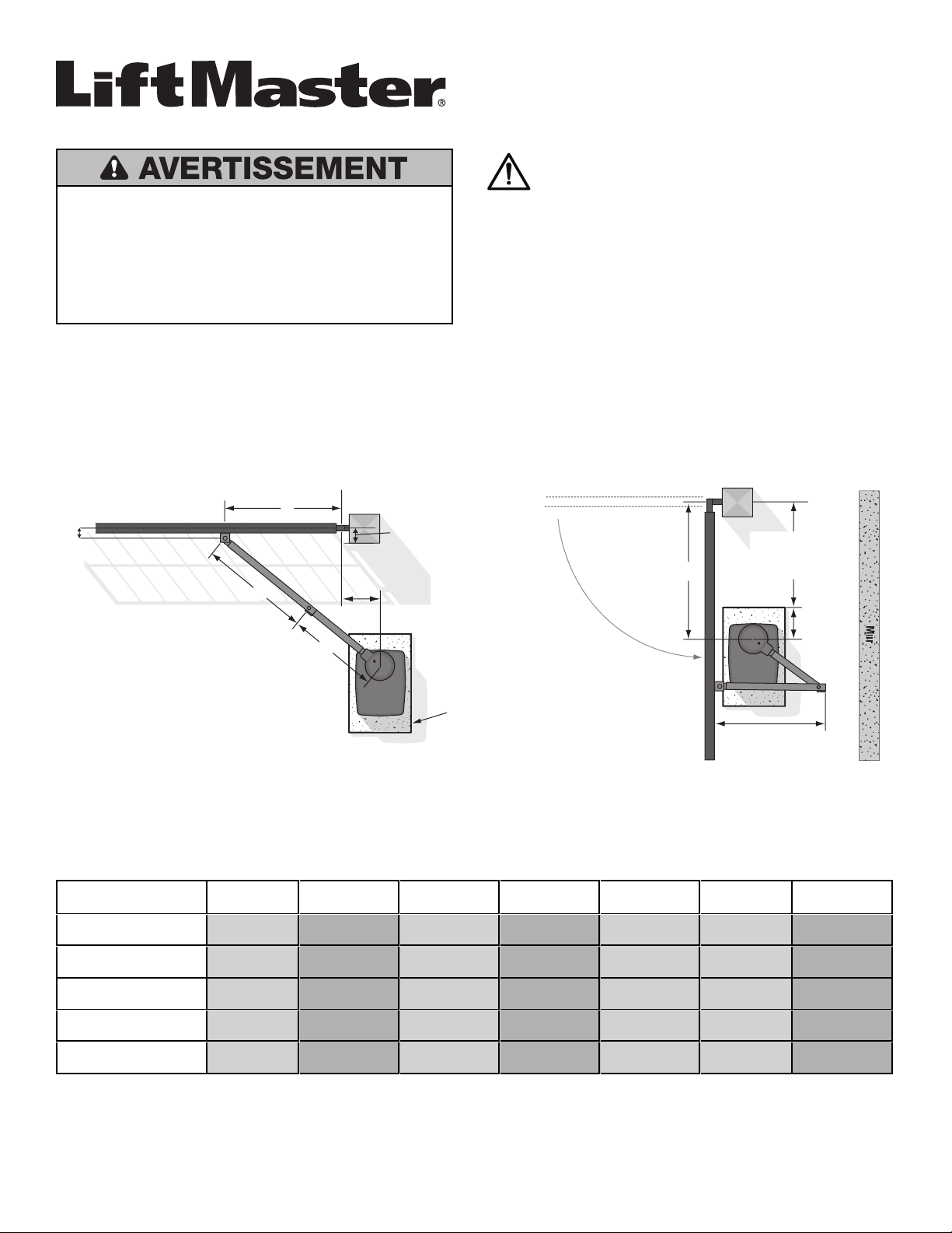
Install the Long Arm
1. Remove the existing output arm from the operator.
2. Attach the long arm to the operator using the long output arm
included in the kit.
Existing
Output Arm
Long Arm
Assembly
1
Long Output Arm
2
Secure the Operator Arm
The length of the arm can be adjusted if necessary. If adjusting the
length, ensure that both sections of the arm are adjusted proportionally.
Use a clamp to temporarily hold the arm in place while determining the
correct measurements.
1. Weld the gate bracket to the gate.
2. Weld the short arm section. Plug/slot weld top and bottom.
3. Weld the long arm section. Plug/slot weld top and bottom.
NOTE: Completely weld around the outer tubing and bracket.
4. Adjust the nuts on the operator arm so the operator arm fits snug on
the output shaft yet still allows enough room to swivel (the handle
must be in a 90° position).
5. Tighten the handle by pushing it down. Test to make sure the
operator arm does not slip on the output shaft.
Manual release handle
1
3
4
5
2
Trousse de bras long d’actionneur de
barrière pivotante
Modèle HDLGARM
Pour réduire le risque de BLESSURES GRAVES, voire MORTELLES:
• DÉCONNECTER l’alimentation (c.a. solaire ou à batterie) AVANT
de procéder à l’installation de l’actionneur ou à une intervention
d’entretien sur celui-ci.
• Mettre hors fonction les deux interrupteurs d’alimentation c.a. et
par batterie.
• Régler le commutateur de réinitialisation à la position RESET.
AVERTISSEMENT: Ce produit peut vous exposer à des produits
chimiques, y compris du plomb, reconnus par l’État de la
Californie comme étant cancérigènes ou pouvant causer des
anomalies congénitales ou d’autres préjudices à l’appareil
reproducteur. Pour plus d’information, aller à
www.P65Warnings.ca.gov
ATTENTION:
UN SUPPORT MASSIF EST FIXÉ À LA BIELLE DU BRAS COURT SUR
L’EMBALLAGE À DES FINS D’EXPÉDITION UNIQUEMENT. PRIÈRE DE
SUIVRE LES INSTRUCTIONS POUR L’ASSEMBLAGE DU BRAS.
Introduction
La trousse de biellette longue est prévue pour être utilisée sur l’actionneur de barrière LiftMaster
®
de modèle HDSW24UL. Pour optimiser et prolonger la
vie utile de l’actionneur, la trousse de biellette longue est recommandée lors de l’installation de barrières de 4,87m (16pi) ou plus.
Consulter le manuel d’installation de l’actionneur de barrière de modèle HDSW24UL pour des instructions complètes d’installation et de sécurité.
Détermination de l’emplacement de la dalle en béton et de l’actionneur
Consulter l’illustration pour déterminer les mesures et l’emplacement de la dalle en béton.
Mur
A
F
B
C
D
25.4 cm
(10 po)
DISTANCE
E
Section de bras long
Section de bras court
Dalle en béton
Centre de la charnière de barrière
D MOINS
25,4 cm (10 po)
Intérieur
Intérieur
Extérieur
Extérieur
REMARQUE : La distance
maximale du centre de la
charnière au bord du poteau ou
de la colonne ne devrait pas
dépasser 10,2 cm (4 po). Si cette
distance est supérieure à 10,2 cm
(4 po), un dispositif de protection
contre le piégeage est alors
nécessaire pour cette zone.
Dimension (A) à (E) du centre d’un point de pivot au centre d’un autre point de pivot.
Suggestion: Les dimensions entre la barrière et la dalle en béton sont toujours de 25,4cm (10po) de moins que la dimensionD.
Exemple: D = 106,7cm (42), si la dimension entre la barrière et la dalle de béton est de 81,3cm (32po).
Tableau LA
Nécessite un moins grand dégagement entre la barrière et le mur.
LONGUEUR DE LA
BARRIÈRE
A B C D E F DISTANCE
6,71m (22pi)
1134kg (2500lb) max.
2,24m (88po) 1,58m (62,5po) 1,46m (57,5po) 1,8m(71po) 27,9cm (11po) 7,6cm (3po) 1,78m (70po)
6,1m (20pi)
1247kg (2750lb) max.
2,03m (80po) 1,48m (58,25po) 1,33m (52,25po) 1,66m (65,5po) 27,9cm (11po) 7,6cm (3po) 1,67m (65,75po)
5,48m (18pi),
1474kg (3250lb) max.
1,83m (72po) 1,35m (53po) 1,19m (47po) 1,49m (58,5po) 27,9cm (11po) 7,6cm (3po) 1,54m (60,5po)
4,88m (16pi)
1701kg (3750lb) max.
1,63m (64po) 1,23m (48,25po) 1,06m (41,75po) 1,33m (52,5po) 27,9cm (11po) 7,6cm (3po) 1,42m (55,75po)
4,27m (14pi)
2041kg (4500lb) max.
1,42m (56po) 1,14m (44,75po) 0,95m (37,25po) 1,27m (50po) 27,9 cm (11po) 7,6cm (3po) 1,33m(52,25po)
Tableau LB - Nécessite un plus grand dégagement entre la barrière et le mur
Nécessite un plus grand dégagement entre la barrière et le mur. Recommandé sur les installations mises à niveau lorsque l’actionneur remplacé n’est pas
de marque LiftMaster
®
.
LONGUEUR DE LA
BARRIÈRE
A B C D E F DISTANCE
6,71m (22pi)
1134kg (2500lb) max.
2,24m (88po) 1,68m (66,25po) 1,45m (57,25po) 1,8m(71po) 38,1 cm (15po) 7,6cm (3po) 1,87m (73,75po)
6,1m (20pi)
1247kg (2750lb) max.
2,03m (80po) 1,57m (61,75po) 1,32m (52po) 1,66m (65,5po) 38,1 cm (15po) 7,6cm (3po) 1,51m (59,25po)
5,49m (18pi)
1474kg (3250lb) max.
1,83m (72po) 1,44m (56,5po) 1,19m (46,75po) 1,49m (58,5po) 38,1 cm (15po) 7,6cm (3po) 1,63m (64po)
4,88m (16pi)
1701kg (3750lb) max.
1,63m (64po) 1,31m (51,75po) 1,05m (41,5po) 1,33m (52,5po) 38,1 cm (15po) 7,6cm (3po) 1,51m(59,25po)
4,27m (14pi)
2041kg (4500lb) max.
1,42m (56po) 1,23m (48,25po) 0,94m (37po) 1,27m (50po) 38,1cm (15po) 7,6cm (3po) 1,42m(55,75po)
Installation de la biellette longue
1. Enlever la biellette de sortie existante de l’actionneur.
2. Fixer la biellette longue à l’actionneur avec la biellette longue de
sortie incluse dans la trousse.
Biellette de
sortie existante
Assemblage
de la biellette
longue
1
Biellette longue de sortie
2
Fixation du bras de l’actionneur
La longueur du bras peut être réglée au besoin. En cas de réglage de la
longueur, s’assurer que les deux sections du bras sont réglées de
manière proportionnelle. Se servir d’une bride pour tenir temporairement
le bras en place tout en déterminant les bonnes mesures.
1. Souder le support de la barrière à celle-ci.
2. Souder la section courte du bras. Souder en bouchon/à entaille le
dessus et le dessous.
3. Souder la section longue du bras. Souder en bouchon/à entaille le
dessus et le dessous.
REMARQUE: Souder complètement autour du tubage extérieur et du
support.
4. Régler les écrous sur le bras de l’actionneur de manière à ce que le
bras soit bien serré sur l’arbre de sortie tout en laissant
suffisamment d’espace pour pivoter (la poignée doit être position
perpendiculaire [90 degrés]).
5. Serrer la poignée en la poussant vers le bas. Mettre à l’essai pour
vérifier que le bras de l’actionneur ne glisse pas sur l’arbre de sortie.
Poignée de
désengagement
manuel
1
3
4
5
2

Juego de brazo largo del operador de
portón pivotante
Modelo HDLGARM
Para reducir el riesgo de LESIONES GRAVES o la MUERTE:
• Desconecte la alimentación eléctrica (CA o solar y batería) antes
de instalar o hacer mantenimiento en el operador.
• Desconecte los interruptores de CA y de la batería.
• Coloque el interruptor de reinicio en la posición de desconexión.
ADVERTENCIA: Este producto puede exponerle a productos
químicos (incluido el plomo), que a consideración del estado de
California causan cáncer, defectos congénitos u otros daños
reproductivos. Para obtener más información, visite
www.P65Warnings.ca.gov
ATENCIÓN:
EN EL EMPAQUE SE SUJETA UNA MÉNSULA SÓLIDA AL ESLABÓN DEL
BRAZO CORTO PARA EL ENVÍO ÚNICAMENTE. SIGA LAS
INSTRUCCIONES PARA EL ENSAMBLAJE DEL BRAZO.
Introducción
El juego de brazo largo es para el modelo de operador de portón HDSW24UL de LiftMaster
®
. A fin de optimizar el desempeño y extender la vida útil del
operador, se recomienda usar el juego de brazo largo cuando instale portones de 4.87 m (16 pies) o más.
Consulte el manual del operador de portón modelo HDSW24UL para ver las instrucciones completas de instalación y seguridad.
Determine la ubicación de la plataforma de cemento y del operador
Consulte la ilustración para determinar las medidas y la ubicación de la plataforma de cemento.
Interior
Exterior
Interior
Exterior
Pared
A
F
B
C
D
25.4 cm
(10 pulg.)
DISTANCIA
E
Sección larga del brazo
Sección corta del brazo
Plataforma de cemento
Centro de la bisagra del portón
D MENOS
25.4 cm (10 pulg.)
NOTA: Solamente debería
haber una distancia mínima
de 10.2 cm (4 pulg.) desde el
centro de la bisagra hasta el
borde del poste o la columna.
Si la distancia supera los
10.2 cm (4 pulg.), se
necesitará protección contra
atrapamiento para esta área.
Dimensión (A) a (E) desde el centro de un punto giratorio hasta el centro de otro punto giratorio.
Sugerencia: La dimensión entre el portón y la plataforma de cemento siempre es 25.4 cm (10 pulg.) menor que la dimensión D.
Por ejemplo: D = 106.7 cm (42 pulg.), si la dimensión entre el portón y la plataforma de cemento es de 81.3 cm (32 pulg.).
Tabla LA
Requiere menos espacio entre el portón y la pared.
LONGITUD DEL PORTÓN A B C D E F DISTANCIA
6.71 m (22 pies)
1,134 kg (2,500 lb) máx.
2.24 m (88 pulg.) 1.58 m (62.5 pulg.) 1.46 m (57.5 pulg.) 1.8m (71 pulg.) 27.9 cm (11 pulg.) 7.6cm (3 pulg.) 1.78 m (70 pulg.)
6.1 m (20 pies)
1,247 kg (2,750 lb) máx.
2.03 m (80 pulg.) 1.48 m (58.25pulg.) 1.33m(52.25 pulg.) 1.66 m (65.5 pulg.) 27.9cm (11pulg.) 7.6 cm (3 pulg.) 1.67m(65.75pulg.)
5.49 m (18 pies)
1,474 kg (2,750 lb) máx.
1.83 m (72 pulg.) 1.35m(53 pulg.) 1.19 m (47 pulg.) 1.49 m (58.5 pulg.) 27.9cm (11pulg.) 7.6 cm (3 pulg.) 1.54 m (60.5 pulg.)
4.88 m (16 pies)
1,701 kg (3,750 lb) máx.
1.63 m (64 pulg.) 1.23 m (48.25pulg.) 1.06m(41.75 pulg.) 1.33 m (52.5 pulg.) 27.9cm (11pulg.) 7.6 cm (3 pulg.) 1.42m(55.75pulg.)
4.26 m (14 pies)
2,041 kg (4,500 lb) máx.
1.42 m (56 pulg.) 1.14 m (44.75pulg.) 0.95m(37.25 pulg.) 1.27m(50pulg.) 27.9 cm (11 pulg.) 7.6 cm (3pulg.) 1.33 m (52.25pulg.)
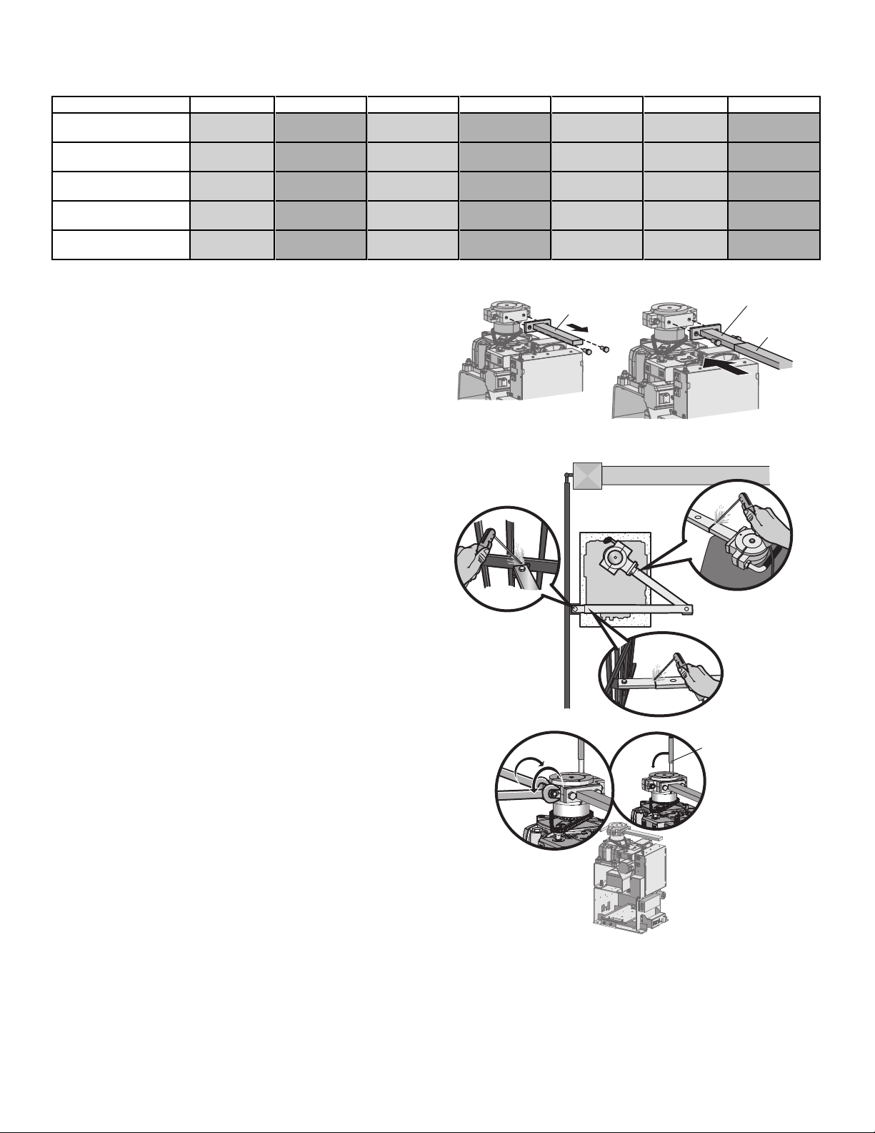
Tabla LB - Requiere más espacio entre el portón y la pared
Requiere más espacio entre el portón y la pared. Se recomienda en instalaciones adaptadas donde el operador reemplazado no es LiftMaster
®
.
LONGITUD DEL PORTÓN A B C D E F DISTANCIA
6.71 m (22 pies)
1,134 kg (2,500 lb) máx.
2.24 m (88 pulg.) 1.68 m (66.25pulg.) 1.45m(57.25 pulg.) 1.8 m (71pulg.) 38.1 cm (15pulg.) 7.6 cm (3 pulg.) 1.87 m (73.75 pulg.)
6.1 m (20 pies)
1,247 kg (2,750 lb) máx.
2.03 m (80 pulg.) 1.57 m (61.75pulg.) 1.32m(52pulg.) 1.66 m (65.5 pulg.) 38.1 cm (15pulg.) 7.6 cm (3 pulg.) 1.51 m (59.25 pulg.)
18 pies
1,474 kg (2,750 lb) máx.
1.83 m (72 pulg.) 1.44 m (56.5 pulg.) 1.19m(46.75 pulg.) 1.49m(58.5 pulg.) 38.1 cm (15 pulg.) 7.6 cm (3 pulg.) 1.63m(64 pulg.)
4.88 m (16 pies)
1,701 kg (3,750 lb) máx.
1.63 m (64 pulg.) 1.31 m (51.75pulg.) 1.05 m (41.5 pulg.) 1.33 m (52.5 pulg.) 38.1cm (15pulg.) 7.6 cm (3 pulg.) 1.51m(59.25pulg.)
4.26 m (14 pies)
2,041 kg (4,500 lb) máx.
1.42 m (56 pulg.) 1.23 m (48.25pulg.) .94 m (37 pulg.) 1.27m(50pulg.) 38.1cm (15pulg.) 7.6 cm (3 pulg.) 1.42m(55.75pulg.)
Instalar el brazo largo
1. Retire el brazo de salida existente del operador.
2. Conecte el brazo largo al operador usando el brazo de salida largo
incluido en el juego.
Brazo de salida
existente
Conjunto de
brazo largo
1
Brazo de salida largo
2
Sujete el brazo del operador
La longitud del brazo se puede ajustar si fuera necesario. Si ajusta la
longitud, asegúrese de ajustar las dos secciones del brazo
proporcionalmente. Use una abrazadera para sostener el brazo
temporalmente en el lugar mientras determina las medidas correctas.
1. Suelde la ménsula del portón al portón.
2. Suelde la sección corta del brazo. Soldadura de tapón/botón
ranurado superior e inferior.
3. Suelde la sección larga del brazo. Soldadura de tapón/botón
ranurado superior e inferior.
NOTA: Realice una soldadura completa alrededor del tubo externo y
la ménsula.
4. Ajuste las tuercas del brazo del operador de manera que este quede
firmemente acoplado al eje de salida y tenga espacio suficiente para
girar (la manija debe estar en una posición de 90°).
5. Ajuste la manija empujándola hacia abajo. Realice una prueba para
asegurarse de que el brazo del operador no se resbale sobre el eje
de salida.
Manija de liberación
manual
1
3
4
5
2

This page intentionally left blank

Contact Information/ Coordonnées/ Información de contacto
LiftMaster.com
LiftMaster Dealer Extranet/ Extranet des détaillants LiftMaster/ Extranet del Distribuidor de LiftMaster:
dealer.liftmaster.com/login
LiftMaster Training Academy/ Académie de formation LiftMaster/ Academia de capacitación de LiftMaster:
liftmastertraining.com
800-528-2806
Mon-Fri 5:00 am to 6:00 pm MST/ Lundi au vendredi 5 h 00 à 18 h 00 HNR/ De lunes a viernes de 5:00 a.m. a 6:00 p.m., horario de la montaña
114-5464-000B
© 2020, LiftMaster
AllRights Reserved
Tous droits réservés
Todos los derechos reservados
300Windsor Drive
Oak Brook, IL60523
LiftMaster.com