Loading ...
Loading ...
Loading ...
Service and maintenance
3-5
3-5
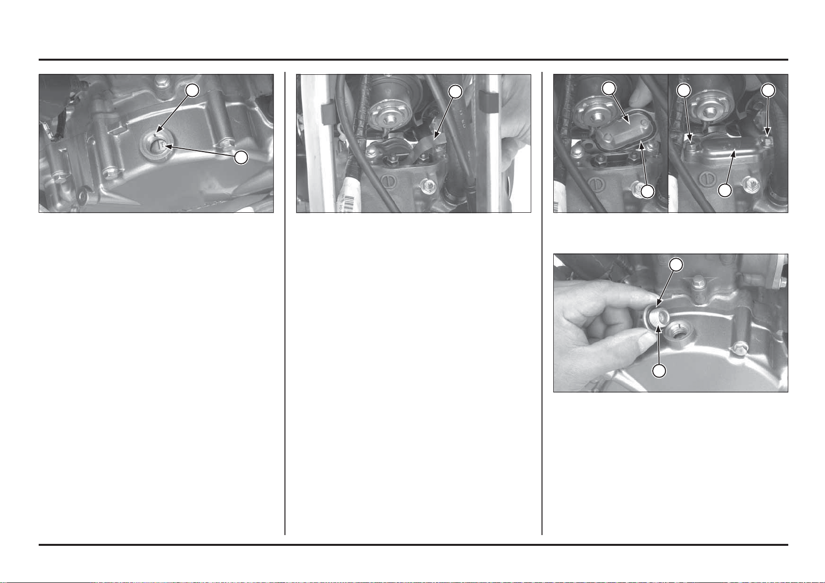
(1) O-RING
(2) TIMING HOLE CAP
Check that the valve adjusting hole cover O-ring is in good
condition, replace if necessary.
Coat the O-rings with clean engine oil and install them in
the valve adjusting hole cover grooves.
Install the valve adjusting hole cover with their “UP” mark
facing up and then install and tighten the bolts securely.
Check the timing hole cap O-ring is in good condition,
replace if necessary.
Install and tighten the timing hole cap.
(1) O-RING
(2) VALVE ADJUSTING HOLE COVER
(3) “UP” MARK (4) BOLTS
Insert a feeler gauge between the rocker arm and
valve stem and measure the intake and exhaust valve
clearances.
Valve clearance:
Intake: 0.12 ± 0.03 mm (0.005 ± 0.001 in)
Exhaust: 0.30 ± 0.03 mm (0.012 ± 0.001 in)
Adjust by loosening the lock nut and turning the adjusting
screw until there is a slight drag on a feeler gauge.
Tools:
Valve adjusting wrench, 10x12 mm (0.39x0.47 in)
(equivalent commercially available)
Tappet wrench, 3 mm (0.118 in) 07908-KE90200
After adjustment, tighten the lock nut while holding the
adjusting screw.
Recheck the valve clearance.
Torque: 14 N•m (1.4 kgf•m, 10.3 lbf•ft)
(1) FEELER GAUGE
Operate the kickstarter pedal and align the “T” mark on
the flywheel with the index mark on the left crankcase
cover.
Make sure the piston is at TDC (Top Dead Center) on the
stroke by moving the rocker arms.
(1) “T” MARK
(2) INDEX MARK
2
1
1
44
3
2
1
2
1
Loading ...
Loading ...
Loading ...