Loading ...
Loading ...
Loading ...
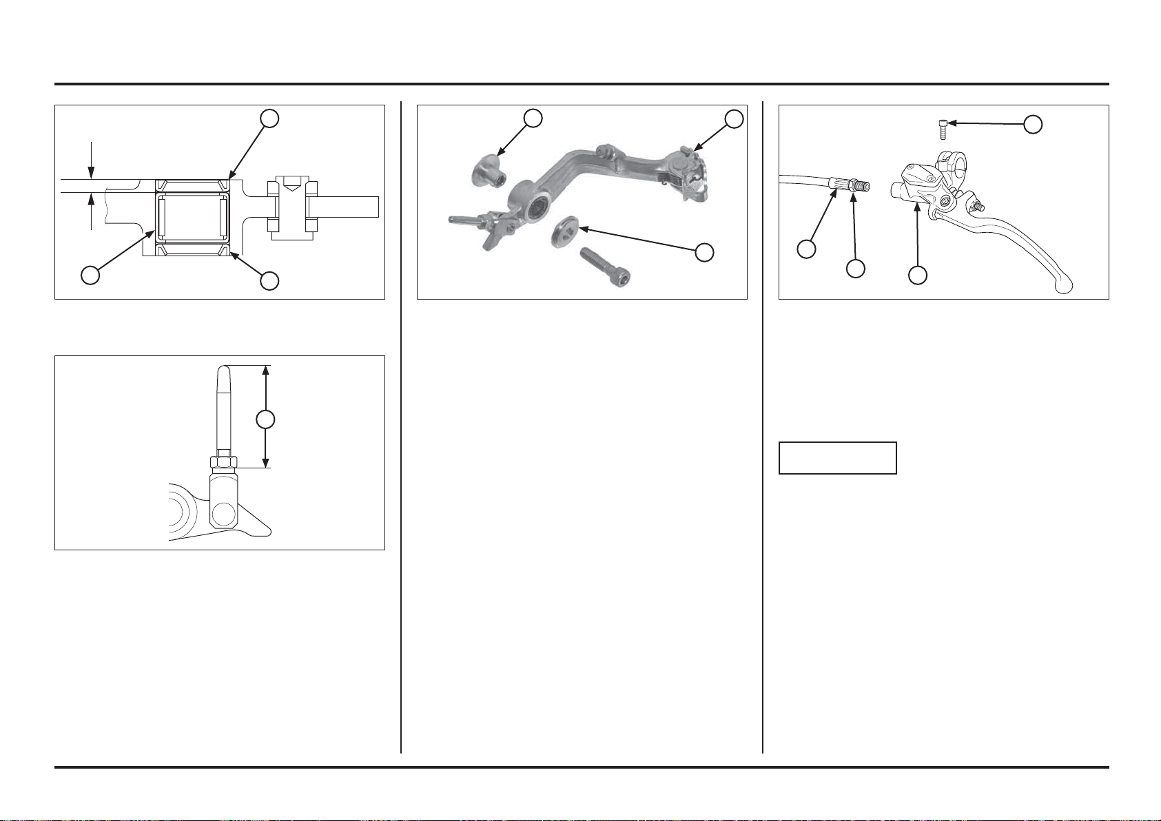
(1) OIL BOLT
(2) CLUTCH HOSE
(3) BOLT
(4) HOLDER
(5) MASTER CYLINDER
Clutch master cylinder
Removal/Installation
NOTICE
Avoid spilling brake fl uid on painted, plastic or rubber
parts. Place a shop rag over these parts whenever the
system is serviced.
When removing the clutch hose bolt, cover the end of
the hose to prevent contamination. Secure the hose
to prevent fl uid from leaking out.
Drain the clutch fluid from the hydraulic system into a
suitable container.
Remove the following:
– Clutch lever
– Clutch hose bolt
– Master cylinder holder bolt and holder
– Master cylinder
Installation
Install the brake pedal and collars.
Install and tighten the pivot nut and bolt.
Torque: 29 N•m (3.0 kgf•m, 22 lbf•ft)
(1) COLLAR B
(2) PEDAL
(3) COLLAR A
(1) STANDARD LENGTH; 35.0 MM
Pivot Bearing Replacement
Remove the dust seals.
Remove the pivot bearing and press a new needle bearing
so that it is 3.0 mm (0.12 in) below the pedal end. Apply
grease inside needle bearing.
Adjust the brake pedal height by loosening the lock nut
and turning the push rod.
Push rod height must be adjusted between 32.5 – 37.5 mm.
(1) BEARING
(2) DUST SEALS
5-29
5-29
Frame servicing
4
3
2
1
3.0 mm (0.12 in)
2
2
1
1
3
2
1
Loading ...
Loading ...
Loading ...