Loading ...
Loading ...
Loading ...
6-6
6-6
Electrical servicing
5
4
3
2
1
3
2
1
PGM-FI
Self-diagnosis system
The PGM-FI system is equipped with the self-diagnostic
system. When any abnormality occurs in the system, the
ECM turns on the MIL and stores a DTC in its erasable
memory.
Fail-safe function
The PGM-FI system is provided with a fail-safe function to
secure a minimum running capability even when there is
trouble in the system. When any abnormality is detected
by the self-diagnosis function, running capability is main-
tained by pre-programmed value in the simulated program
map. When any abnormality is detected in the injector,
the fail-safe function stops the engine to protect it from
damage.
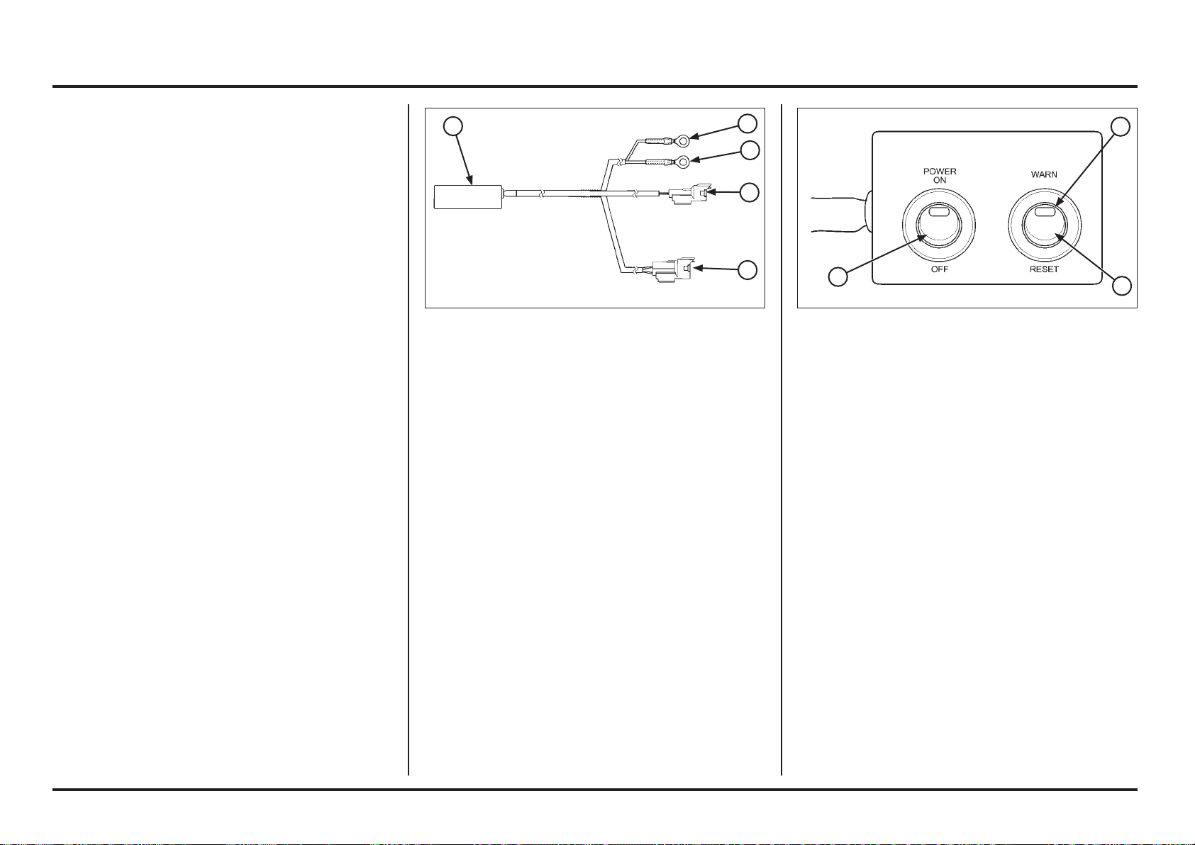
(1) PGM WARNING UNIT ASSEMBLY
(2) RED WIRE EYELET
(3) GREEN WIRE EYELET
(4) 2P (BLACK) CONNECTOR
(5) 4P (RED) CONNECTOR
DTC readout procedure
–
Disconnect the fuel pump 2P (Black) connector.
– Disconnect the condenser 2P (Black) connector and
connect a warning unit connector to the wire harness
side.
Tool:
PGM-FI warning unit assembly 38890-NN4-306
– Make sure PGM-FI warning unit assembly power switch
is in OFF position.
– Connect the waring unit 4P (Red) connector to the ser-
vice check 4P (Red) connector.
– Connect the fully charged 12 V battery to the warning
unit terminals (red wire eyelet to the battery positive
terminal and green wire eyelet to the negative termi-
nal).
(1) POWER SWITCH
(2) MIL
(3) WARN/RESET SWITCH
– Turn the PGM warning unit “WARN/RESET” switch to
the warning side as shown.
– Turn the power switch ON, check that the MIL.
– If the ECM has no self diagnosis memory data, the MIL
will illuminate, when you turn the power switch ON.
– If the ECM has self diagnosis memory data, the MIL
will start blinking when you turn the power switch ON.
– Note how many times the MIL blinks, and determine
the cause of the problem (page 6-7).
Loading ...
Loading ...
Loading ...