Loading ...
Loading ...
Loading ...
INSTALLATION
To avoid possible SERIOUS INJURY from a falling operator:
• Fasten the operator SECURELY to structural supports of the
building.
• Concrete anchors MUST be used if installing ANY brackets
into masonry.
TYPICAL INSTALLATION
NOTE: Refer to Operator Dimensions in the introduction for
general information.
1
Determine the clearance necessary for the door to pass
between the operator and the wall. This dimension must be
less than 4" (10.16 cm), it may be necessary to shim the angle
mounting brackets out from the wall accordingly.
2
With the door fully closed, locate the vertical center-line of the
door and mark this line on the wall above the door. Measure
18" (45.7 cm) to the left of this line if the door slides
left-to-close or 18" (45.7 cm) to the right of this line if the
door slides right-to-close.
NOTE: For bi-parting doors, omit this step. The track should
extend 3-1/2 feet (1.06 m) beyond the door opening.
3
Set the assembled operator into position and mark the
holes for the angle mounting brackets on the wall, as low as
possible without interfering with door travel. Drill holes in
the wall for mounting. Through-bolts are recommended for
this purpose. If wall construction does not permit the use of
through-bolts, lag bolts and shields may be used.
4
Secure the assembled operator to the wall.
IMPORTANT: BE SURE OPERATOR, TRACK AND DOOR
TRACK ARE PARALLEL.
Check that the door clears the operator when moving. Adjust
the track hangers on the angle mounting brackets to the
desired position and tighten all bolts. It is recommended
that at least one sway brace be used (not provided) between
the wall and one of the track hangers for increased rigidity,
especially on large or heavy doors.
5
Mount the door disconnect mechanism on the center-line
of the door so that the top of the bracket is no more than
1-1/2" (3.8 cm) below the trolley. This mechanism may be
adjusted both front to back and up and down to align the
disconnect pin. It may be necessary to shim between the
mechanism and the door to bring the disconnect pin out into
the center-line of the track.
NOTE: For bi-parting doors, mount each door disconnect
mechanism centered on a line 24" (61 cm) from the door
edge.
6
Move the door so that the disconnect pin is directly aligned
with the hole in the trolley and engage the disconnect pin in
hole.
NOTE: For bi-parting doors, it is necessary to bring the doors
to a fully closed position for proper synchronization. With
both disconnect pins engaged in their respective trolleys, lift
the drive chain over the three studs on the bi-part trolley and
secure the chain with the hardware provided.
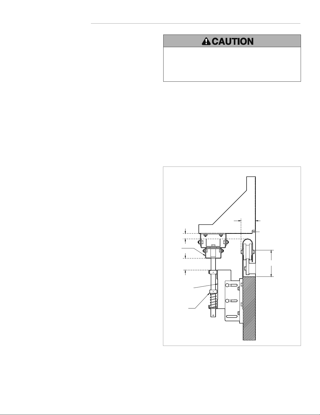
4"
(10.16 cm)
max.
6-1/4" (15.9 cm) max.
Bottom of Track
Top of Door
Angle Mounting Brackets
should not interfere with
door travel
1" (2.5 cm) min.
1-1/2" (3.8 cm)
min.
Trolley
Operator clearance
from wall
Door Disconnect
Mechanism
Screw Collar
7
Adjust the screw collars on the disconnect pin so that it enters
into the trolley bracket about 3/4" (1.9 cm).
8
Mount the chain retaining bracket (with keyhole slot) at a
convenient height on the door, directly below and aligned with
the disconnect chain. Mount the chain retaining bracket so
that the keyhole is in the horizontal plane (repeat for bi-part
door).
8 Installation
Loading ...
Loading ...
Loading ...